US10793056B2 - Snow plow headlamp - Google Patents
Snow plow headlamp Download PDFInfo
- Publication number
- US10793056B2 US10793056B2 US16/157,813 US201816157813A US10793056B2 US 10793056 B2 US10793056 B2 US 10793056B2 US 201816157813 A US201816157813 A US 201816157813A US 10793056 B2 US10793056 B2 US 10793056B2
- Authority
- US
- United States
- Prior art keywords
- housing
- led
- snow plow
- headlamp
- accessory
- Prior art date
- Legal status (The legal status is an assumption and is not a legal conclusion. Google has not performed a legal analysis and makes no representation as to the accuracy of the status listed.)
- Active, expires
Links
Images


Classifications
-
- B—PERFORMING OPERATIONS; TRANSPORTING
- B60—VEHICLES IN GENERAL
- B60Q—ARRANGEMENT OF SIGNALLING OR LIGHTING DEVICES, THE MOUNTING OR SUPPORTING THEREOF OR CIRCUITS THEREFOR, FOR VEHICLES IN GENERAL
- B60Q1/00—Arrangement of optical signalling or lighting devices, the mounting or supporting thereof or circuits therefor
- B60Q1/02—Arrangement of optical signalling or lighting devices, the mounting or supporting thereof or circuits therefor the devices being primarily intended to illuminate the way ahead or to illuminate other areas of way or environments
- B60Q1/04—Arrangement of optical signalling or lighting devices, the mounting or supporting thereof or circuits therefor the devices being primarily intended to illuminate the way ahead or to illuminate other areas of way or environments the devices being headlights
- B60Q1/0483—Arrangement of optical signalling or lighting devices, the mounting or supporting thereof or circuits therefor the devices being primarily intended to illuminate the way ahead or to illuminate other areas of way or environments the devices being headlights mounted on a bracket, e.g. details concerning the mouting of the lamps on the vehicle body
-
- B—PERFORMING OPERATIONS; TRANSPORTING
- B60—VEHICLES IN GENERAL
- B60Q—ARRANGEMENT OF SIGNALLING OR LIGHTING DEVICES, THE MOUNTING OR SUPPORTING THEREOF OR CIRCUITS THEREFOR, FOR VEHICLES IN GENERAL
- B60Q1/00—Arrangement of optical signalling or lighting devices, the mounting or supporting thereof or circuits therefor
- B60Q1/0029—Spatial arrangement
- B60Q1/0041—Spatial arrangement of several lamps in relation to each other
-
- B—PERFORMING OPERATIONS; TRANSPORTING
- B60—VEHICLES IN GENERAL
- B60Q—ARRANGEMENT OF SIGNALLING OR LIGHTING DEVICES, THE MOUNTING OR SUPPORTING THEREOF OR CIRCUITS THEREFOR, FOR VEHICLES IN GENERAL
- B60Q1/00—Arrangement of optical signalling or lighting devices, the mounting or supporting thereof or circuits therefor
- B60Q1/02—Arrangement of optical signalling or lighting devices, the mounting or supporting thereof or circuits therefor the devices being primarily intended to illuminate the way ahead or to illuminate other areas of way or environments
- B60Q1/04—Arrangement of optical signalling or lighting devices, the mounting or supporting thereof or circuits therefor the devices being primarily intended to illuminate the way ahead or to illuminate other areas of way or environments the devices being headlights
- B60Q1/18—Arrangement of optical signalling or lighting devices, the mounting or supporting thereof or circuits therefor the devices being primarily intended to illuminate the way ahead or to illuminate other areas of way or environments the devices being headlights being additional front lights
-
- B—PERFORMING OPERATIONS; TRANSPORTING
- B60—VEHICLES IN GENERAL
- B60Q—ARRANGEMENT OF SIGNALLING OR LIGHTING DEVICES, THE MOUNTING OR SUPPORTING THEREOF OR CIRCUITS THEREFOR, FOR VEHICLES IN GENERAL
- B60Q1/00—Arrangement of optical signalling or lighting devices, the mounting or supporting thereof or circuits therefor
- B60Q1/02—Arrangement of optical signalling or lighting devices, the mounting or supporting thereof or circuits therefor the devices being primarily intended to illuminate the way ahead or to illuminate other areas of way or environments
- B60Q1/24—Arrangement of optical signalling or lighting devices, the mounting or supporting thereof or circuits therefor the devices being primarily intended to illuminate the way ahead or to illuminate other areas of way or environments for lighting other areas than only the way ahead
-
- F—MECHANICAL ENGINEERING; LIGHTING; HEATING; WEAPONS; BLASTING
- F21—LIGHTING
- F21S—NON-PORTABLE LIGHTING DEVICES; SYSTEMS THEREOF; VEHICLE LIGHTING DEVICES SPECIALLY ADAPTED FOR VEHICLE EXTERIORS
- F21S41/00—Illuminating devices specially adapted for vehicle exteriors, e.g. headlamps
- F21S41/10—Illuminating devices specially adapted for vehicle exteriors, e.g. headlamps characterised by the light source
- F21S41/14—Illuminating devices specially adapted for vehicle exteriors, e.g. headlamps characterised by the light source characterised by the type of light source
- F21S41/141—Light emitting diodes [LED]
- F21S41/143—Light emitting diodes [LED] the main emission direction of the LED being parallel to the optical axis of the illuminating device
-
- F—MECHANICAL ENGINEERING; LIGHTING; HEATING; WEAPONS; BLASTING
- F21—LIGHTING
- F21S—NON-PORTABLE LIGHTING DEVICES; SYSTEMS THEREOF; VEHICLE LIGHTING DEVICES SPECIALLY ADAPTED FOR VEHICLE EXTERIORS
- F21S41/00—Illuminating devices specially adapted for vehicle exteriors, e.g. headlamps
- F21S41/10—Illuminating devices specially adapted for vehicle exteriors, e.g. headlamps characterised by the light source
- F21S41/14—Illuminating devices specially adapted for vehicle exteriors, e.g. headlamps characterised by the light source characterised by the type of light source
- F21S41/141—Light emitting diodes [LED]
- F21S41/147—Light emitting diodes [LED] the main emission direction of the LED being angled to the optical axis of the illuminating device
- F21S41/148—Light emitting diodes [LED] the main emission direction of the LED being angled to the optical axis of the illuminating device the main emission direction of the LED being perpendicular to the optical axis
-
- F—MECHANICAL ENGINEERING; LIGHTING; HEATING; WEAPONS; BLASTING
- F21—LIGHTING
- F21S—NON-PORTABLE LIGHTING DEVICES; SYSTEMS THEREOF; VEHICLE LIGHTING DEVICES SPECIALLY ADAPTED FOR VEHICLE EXTERIORS
- F21S41/00—Illuminating devices specially adapted for vehicle exteriors, e.g. headlamps
- F21S41/10—Illuminating devices specially adapted for vehicle exteriors, e.g. headlamps characterised by the light source
- F21S41/14—Illuminating devices specially adapted for vehicle exteriors, e.g. headlamps characterised by the light source characterised by the type of light source
- F21S41/141—Light emitting diodes [LED]
- F21S41/151—Light emitting diodes [LED] arranged in one or more lines
-
- F—MECHANICAL ENGINEERING; LIGHTING; HEATING; WEAPONS; BLASTING
- F21—LIGHTING
- F21S—NON-PORTABLE LIGHTING DEVICES; SYSTEMS THEREOF; VEHICLE LIGHTING DEVICES SPECIALLY ADAPTED FOR VEHICLE EXTERIORS
- F21S41/00—Illuminating devices specially adapted for vehicle exteriors, e.g. headlamps
- F21S41/20—Illuminating devices specially adapted for vehicle exteriors, e.g. headlamps characterised by refractors, transparent cover plates, light guides or filters
- F21S41/25—Projection lenses
- F21S41/255—Lenses with a front view of circular or truncated circular outline
-
- F—MECHANICAL ENGINEERING; LIGHTING; HEATING; WEAPONS; BLASTING
- F21—LIGHTING
- F21S—NON-PORTABLE LIGHTING DEVICES; SYSTEMS THEREOF; VEHICLE LIGHTING DEVICES SPECIALLY ADAPTED FOR VEHICLE EXTERIORS
- F21S41/00—Illuminating devices specially adapted for vehicle exteriors, e.g. headlamps
- F21S41/20—Illuminating devices specially adapted for vehicle exteriors, e.g. headlamps characterised by refractors, transparent cover plates, light guides or filters
- F21S41/28—Cover glass
-
- F—MECHANICAL ENGINEERING; LIGHTING; HEATING; WEAPONS; BLASTING
- F21—LIGHTING
- F21S—NON-PORTABLE LIGHTING DEVICES; SYSTEMS THEREOF; VEHICLE LIGHTING DEVICES SPECIALLY ADAPTED FOR VEHICLE EXTERIORS
- F21S41/00—Illuminating devices specially adapted for vehicle exteriors, e.g. headlamps
- F21S41/20—Illuminating devices specially adapted for vehicle exteriors, e.g. headlamps characterised by refractors, transparent cover plates, light guides or filters
- F21S41/285—Refractors, transparent cover plates, light guides or filters not provided in groups F21S41/24-F21S41/28
-
- F—MECHANICAL ENGINEERING; LIGHTING; HEATING; WEAPONS; BLASTING
- F21—LIGHTING
- F21S—NON-PORTABLE LIGHTING DEVICES; SYSTEMS THEREOF; VEHICLE LIGHTING DEVICES SPECIALLY ADAPTED FOR VEHICLE EXTERIORS
- F21S41/00—Illuminating devices specially adapted for vehicle exteriors, e.g. headlamps
- F21S41/20—Illuminating devices specially adapted for vehicle exteriors, e.g. headlamps characterised by refractors, transparent cover plates, light guides or filters
- F21S41/29—Attachment thereof
-
- F—MECHANICAL ENGINEERING; LIGHTING; HEATING; WEAPONS; BLASTING
- F21—LIGHTING
- F21S—NON-PORTABLE LIGHTING DEVICES; SYSTEMS THEREOF; VEHICLE LIGHTING DEVICES SPECIALLY ADAPTED FOR VEHICLE EXTERIORS
- F21S41/00—Illuminating devices specially adapted for vehicle exteriors, e.g. headlamps
- F21S41/30—Illuminating devices specially adapted for vehicle exteriors, e.g. headlamps characterised by reflectors
- F21S41/32—Optical layout thereof
- F21S41/321—Optical layout thereof the reflector being a surface of revolution or a planar surface, e.g. truncated
-
- F—MECHANICAL ENGINEERING; LIGHTING; HEATING; WEAPONS; BLASTING
- F21—LIGHTING
- F21S—NON-PORTABLE LIGHTING DEVICES; SYSTEMS THEREOF; VEHICLE LIGHTING DEVICES SPECIALLY ADAPTED FOR VEHICLE EXTERIORS
- F21S41/00—Illuminating devices specially adapted for vehicle exteriors, e.g. headlamps
- F21S41/30—Illuminating devices specially adapted for vehicle exteriors, e.g. headlamps characterised by reflectors
- F21S41/39—Attachment thereof
-
- F—MECHANICAL ENGINEERING; LIGHTING; HEATING; WEAPONS; BLASTING
- F21—LIGHTING
- F21S—NON-PORTABLE LIGHTING DEVICES; SYSTEMS THEREOF; VEHICLE LIGHTING DEVICES SPECIALLY ADAPTED FOR VEHICLE EXTERIORS
- F21S41/00—Illuminating devices specially adapted for vehicle exteriors, e.g. headlamps
- F21S41/50—Illuminating devices specially adapted for vehicle exteriors, e.g. headlamps characterised by aesthetic components not otherwise provided for, e.g. decorative trim, partition walls or covers
-
- E—FIXED CONSTRUCTIONS
- E01—CONSTRUCTION OF ROADS, RAILWAYS, OR BRIDGES
- E01H—STREET CLEANING; CLEANING OF PERMANENT WAYS; CLEANING BEACHES; DISPERSING OR PREVENTING FOG IN GENERAL CLEANING STREET OR RAILWAY FURNITURE OR TUNNEL WALLS
- E01H5/00—Removing snow or ice from roads or like surfaces; Grading or roughening snow or ice
- E01H5/04—Apparatus propelled by animal or engine power; Apparatus propelled by hand with driven dislodging or conveying levelling elements, conveying pneumatically for the dislodged material
- E01H5/06—Apparatus propelled by animal or engine power; Apparatus propelled by hand with driven dislodging or conveying levelling elements, conveying pneumatically for the dislodged material dislodging essentially by non-driven elements, e.g. scraper blades, snow-plough blades, scoop blades
- E01H5/061—Apparatus propelled by animal or engine power; Apparatus propelled by hand with driven dislodging or conveying levelling elements, conveying pneumatically for the dislodged material dislodging essentially by non-driven elements, e.g. scraper blades, snow-plough blades, scoop blades by scraper blades
-
- F—MECHANICAL ENGINEERING; LIGHTING; HEATING; WEAPONS; BLASTING
- F21—LIGHTING
- F21Y—INDEXING SCHEME ASSOCIATED WITH SUBCLASSES F21K, F21L, F21S and F21V, RELATING TO THE FORM OR THE KIND OF THE LIGHT SOURCES OR OF THE COLOUR OF THE LIGHT EMITTED
- F21Y2115/00—Light-generating elements of semiconductor light sources
- F21Y2115/10—Light-emitting diodes [LED]
Definitions
- This invention relates generally to snow plows, and more particularly to headlamps for snow plows.
- a typical snow plow and mount assembly has a mount frame that mounts to the vehicle below the front bumper, and a snow plow assembly that removably mounts to the vehicle via the mount frame.
- a typical snow plow assembly has a lift frame with arms that are removably received in receivers on the mount frame, an A-frame operably pivotally connected on a rearward end to the lift frame for pivoting about a generally transverse horizontal axis, and a blade operably pivotally connected on a forward end of the A-frame for pivoting about a generally vertical axis.
- An actuator for example hydraulic cylinder, is operably connected to the lift frame and the A-frame for pivoting the A-frame and hence blade up and down about the transverse horizontal axis.
- a pair of actuators, for example hydraulic cylinders is operably connected to the blade and the A-frame, one actuator being located on each lateral side of the vertical pivot axis, for pivoting the blade about the vertical axis.
- a typical lift frame has an upper transverse frame member.
- Conventional snow plow headlamps are mounted to this frame member. This places them at a vertical position above the blade when in the raised position, thus allowing light from them to illuminate ahead of the vehicle.
- a typical plow blade can be as wide as, or even wider than, the vehicle to which it is mounted. An operator must be able to keep track of the ends of the plow blade when plowing to avoid obstacles. Since current snow plow headlamps only illuminate ahead of the vehicle, the ends of the plow blade and their surroundings are not directly illuminated, thus making keeping tack of the ends of the plow blade and surrounding obstacles difficult.
- a snow plow headlamp comprises a housing adapted to be mounted to a frame member of a snow plow assembly, at least a first forwardly directed LED mounted in the housing between opposite ends of the housing and configured to illuminate ahead of a vehicle to which the snow plow assembly is mounted, a second forwardly directed LED mounted in the housing adjacent one of the ends of the housing, a reflector mounted in the housing on a side of the second LED opposite the one end of the housing and configured to reflect light from the second LED to illuminate to a side of the vehicle to which the snow plow assembly is mounted, and a transparent cover mounted to the housing.
- the transparent cover can include a forward facing portion and a side facing portion adjacent to the second LED.
- the at least a first forwardly directed LED can comprise a plurality of LED's spaced between the second LED and the other end of the housing.
- Each of the plurality of LED's can include a respective lens mounted in the housing forward of a respective one of the plurality of LED's.
- the headlamp can further include an intermediate cover between the housing and the transparent cover, the intermediate cover including an opening for each lens. All of the LED's and lenses can be mounted to a printed circuit board which itself is mounted in the housing.
- a snow plow assembly comprises a lift frame adapted to be removably connected to a vehicle, an A-frame operably pivotally connected on a rearward end to the lift frame for pivoting about a generally transverse horizontal axis, a blade operably pivotally connected on a forward end of the A-frame for pivoting about a generally vertical axis, and a pair of the aforementioned headlamps mounted to the lift frame.
- an accessory headlamp comprises a housing adapted to be mounted to a frame member of an accessory, at least a first forwardly directed light emitter mounted in the housing between opposite ends of the housing and configured to illuminate ahead of the accessory, a second forwardly directed light emitter mounted in the housing adjacent one of the ends of the housing, a reflector mounted in the housing on a side of the second light emitter opposite the one end of the housing and configured to reflect light from the second light emitter to illuminate to a side of the accessory, and a transparent outer lens mounted to the housing, the lens having a first forwardly facing portion and a second sidewardly facing portion adjacent the second light emitter.
- an accessory headlamp comprises a housing adapted to be mounted to a frame member of an accessory, at least a first forwardly directed light emitter mounted in the housing between opposite ends of the housing and configured to illuminate ahead of the accessory, a second light emitter mounted in the housing adjacent one of said ends of the housing and configured to project light from the second light emitter to illuminate to a side of the accessory, and a transparent outer lens mounted to the housing, the lens having a first forwardly facing portion and a second sidewardly facing portion adjacent the second light emitter.
- FIG. 1 is a top view of a snow plow assembly mounted to a vehicle, the snow plow assembly including a pair of the inventive headlamps according to the principles of the present invention.
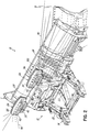
- FIG. 2 is a right, rear, top perspective view of the snow plow assembly of FIG. 1 .
- FIG. 3 is a right, front, top perspective view of the driver's side headlamp of FIG. 1 .
- FIG. 4 is an exploded perspective view of the lamp of FIG. 3 .
- FIG. 5 is a cross-sectional view taken along line 5 - 5 in FIG. 3 .
- FIG. 6 is a right, front, top, cross-sectional perspective view, enlarged, of the outboard end of the driver's side headlamp.
- the assembly includes a snow plow assembly 12 and a mount frame 14 .
- the snow plow assembly 12 comprises a lift frame 20 adapted to be removably connected to a vehicle via the mount frame 14 , an A-frame 22 operably pivotally connected on a rearward end to the lift frame 20 for pivoting about a generally transverse horizontal axis, a blade 24 operably pivotally connected on a forward end of the A-frame 22 for pivoting about a generally vertical axis, and a pair headlamps 26 mounted to an upper transverse frame member 28 of the lift frame 20 .
- each headlamp 26 includes a housing 30 mounted to a base or mounting plate 32 .
- Base 32 includes a pair of threaded bolts or posts 34 that pass through holes in the upper transverse frame member 28 of the lift frame 20 onto which are threaded nuts (not shown) to secure the headlamp 26 to the frame member 28 .
- Housing 30 can be fabricated of Xenoy which prevents rust and corrosion.
- a rear side of the housing 30 includes a number of stiffening ribs 40 , and a plug or integral connector 42 for connecting a wiring harness (not shown) to the headlamp 26 to supply electricity from the vehicle's electrical system to the headlamp 26 .
- a main printed circuit board (“PCB”) 44 is mounted in the housing 30 .
- the PCB 44 has a plurality of white light emitting diode light engines (“LED's”) mounted to it.
- the headlamp 26 can include LED 50 , three LED's 52 , two LED's 54 , LED 56 , and two LED's 58 .
- the LED 50 is the LED light engine for a Low Beam (“LB”) aspherical lens.
- the LED's 52 are the LED light engines for wide spread D-lenses.
- the LED's 54 are the LED light engines for skinny fog D-lenses.
- the LED 56 is the LED light engine for a High Beam (“HB”) aspherical lens.
- LB Low Beam
- HB High Beam
- the LED's 58 are the LED light engines for HB Compound Parabolic Concentrator (“CPC”) lenses.
- the PCB 44 further has a plurality of lenses mounted to it, each of which corresponds to one of the LED's.
- the headlamp can include lens 60 , three lenses 62 , two lenses 64 , lens 66 , and two lenses 68 .
- the lens 60 is an aspherical lens.
- the lenses 62 are wide spread D-lenses.
- the lenses 64 are skinny fog D-lenses.
- the lens 66 is an HB aspherical lens.
- the lenses 68 are HB CPC lenses.
- the LED's 50 , 52 , 54 , 56 , and 58 , and their respective lenses 60 , 62 , 64 , 66 , and 68 provide forwardly directed illumination for the vehicle driver.
- Suitable LED's 50 , 52 , 54 , 56 , and 58 , and respective lenses 60 , 62 , 64 , 66 , and 68 are available from J. W. Speaker of Germantown, Wis. Other combinations of LED's and lenses can be used.
- the PCB 44 has another white light LED 70 mounted to it, adjacent an end of the housing 30 .
- a reflector 72 partially surrounds LED 70 and serves to reflect light from the LED 70 toward the end of the housing 30 .
- a suitable LED 70 is model number 7416030 available from J. W. Speaker of Germantown, Wis.
- the reflector 72 may be fabricated of polycarbonate, and it may have a faceted geometry.
- the PCB 44 also has a light blade optic 74 mounted to it.
- the purpose of the light blade optic 74 is to provide compliant optical patterns for daytime running lights, turn signals, and front position functions.
- the headlamp 26 includes an inner or intermediate cover or bezel 76 that can be fabricated of polycarbonate.
- the cover 76 includes openings 80 , 82 , 84 , 86 , and 88 to accommodate lenses 60 , 62 , 64 , 66 , and 68 , respectively.
- the cover 76 also includes an opening 94 to accommodate the light blade optic 74 .
- the headlamp 26 also includes an outer transparent cover or lens assembly 96 that can be fabricated of UV-resistant polycarbonate.
- Cover 96 includes a forward facing portion 98 and a side facing portion or window 100 adjacent LED 70 .
- Side facing portion 100 includes a plurality of vertical, V-shaped in cross-section grooves 102 , referred to as B-surface optics, the purpose of which is create the desired optical pattern to illuminate the end of the plow blade and beyond.
- Cover 96 is a snap fit to housing 30 , sandwiching intermediate cover 76 between it and housing 30 .
- FIG. 1 there is illustrated the light beam pattern 110 generated by LED 70 and reflector 72 for each headlamp 26 as light from the LED 70 passes through side facing portion 98 of transparent cover 96 .
- the LED's 70 and reflectors 72 of the headlamps 26 effectively illuminate the ends of the plow blade 24 and beyond, allowing an operator to safely avoid any obstacles that the ends of the plow blade 24 might otherwise come in contact with.
Abstract
Description
Claims (20)
Priority Applications (2)
| Application Number | Priority Date | Filing Date | Title |
|---|---|---|---|
| US16/157,813 US10793056B2 (en) | 2018-10-11 | 2018-10-11 | Snow plow headlamp |
| CA3058523A CA3058523A1 (en) | 2018-10-11 | 2019-10-11 | Snow plow headlamp |
Applications Claiming Priority (1)
| Application Number | Priority Date | Filing Date | Title |
|---|---|---|---|
| US16/157,813 US10793056B2 (en) | 2018-10-11 | 2018-10-11 | Snow plow headlamp |
Publications (2)
| Publication Number | Publication Date |
|---|---|
| US20200114803A1 US20200114803A1 (en) | 2020-04-16 |
| US10793056B2 true US10793056B2 (en) | 2020-10-06 |
Family
ID=70155991
Family Applications (1)
| Application Number | Title | Priority Date | Filing Date |
|---|---|---|---|
| US16/157,813 Active 2039-02-12 US10793056B2 (en) | 2018-10-11 | 2018-10-11 | Snow plow headlamp |
Country Status (2)
| Country | Link |
|---|---|
| US (1) | US10793056B2 (en) |
| CA (1) | CA3058523A1 (en) |
Families Citing this family (6)
| Publication number | Priority date | Publication date | Assignee | Title |
|---|---|---|---|---|
| CN106812110A (en) * | 2015-11-30 | 2017-06-09 | 南京德朔实业有限公司 | Snowplough |
| PL3565928T3 (en) * | 2017-01-05 | 2021-12-13 | 9407-4895 Québec Inc. | Scraping device for clearing a roadway surface |
| US20180347803A1 (en) * | 2017-06-06 | 2018-12-06 | Briggs & Stratton Corporation | Lighting System for Outdoor Power Equipment |
| US11466417B2 (en) | 2020-03-12 | 2022-10-11 | Ricky A. Weihl | Plow assembly |
| US11248354B2 (en) | 2020-03-12 | 2022-02-15 | Ricky A. Weihl | Plow assembly |
| US11795642B1 (en) * | 2022-09-08 | 2023-10-24 | Ricky A. Weihl | Plow assembly |
Citations (7)
| Publication number | Priority date | Publication date | Assignee | Title |
|---|---|---|---|---|
| US1205916A (en) * | 1915-05-03 | 1916-11-21 | Eugene F Meador | Illuminating apparatus. |
| US4758932A (en) * | 1987-07-13 | 1988-07-19 | J. I. Case Company | Dual front headlight assembly |
| USD399326S (en) | 1997-12-05 | 1998-10-06 | The Louis Berkman Company | Auxiliary light for a vehicle |
| US6015219A (en) | 1998-02-05 | 2000-01-18 | The Louis Berkman Company | Auxilliary lamp unit |
| US6138388A (en) * | 2000-02-22 | 2000-10-31 | The Louis Berkman Company | Plug system for a snowplow |
| US6332699B1 (en) * | 2000-04-03 | 2001-12-25 | Hyun Jo Lee | Auxiliary lighting of right and left bearings for automobile |
| US7073930B2 (en) * | 2004-09-01 | 2006-07-11 | Lear Corporation | Aimable vehicle lamp assembly |
-
2018
- 2018-10-11 US US16/157,813 patent/US10793056B2/en active Active
-
2019
- 2019-10-11 CA CA3058523A patent/CA3058523A1/en active Pending
Patent Citations (7)
| Publication number | Priority date | Publication date | Assignee | Title |
|---|---|---|---|---|
| US1205916A (en) * | 1915-05-03 | 1916-11-21 | Eugene F Meador | Illuminating apparatus. |
| US4758932A (en) * | 1987-07-13 | 1988-07-19 | J. I. Case Company | Dual front headlight assembly |
| USD399326S (en) | 1997-12-05 | 1998-10-06 | The Louis Berkman Company | Auxiliary light for a vehicle |
| US6015219A (en) | 1998-02-05 | 2000-01-18 | The Louis Berkman Company | Auxilliary lamp unit |
| US6138388A (en) * | 2000-02-22 | 2000-10-31 | The Louis Berkman Company | Plug system for a snowplow |
| US6332699B1 (en) * | 2000-04-03 | 2001-12-25 | Hyun Jo Lee | Auxiliary lighting of right and left bearings for automobile |
| US7073930B2 (en) * | 2004-09-01 | 2006-07-11 | Lear Corporation | Aimable vehicle lamp assembly |
Non-Patent Citations (1)
| Title |
|---|
| Jason Torchinsky, A Tribute to the Most Un-Appreciated Light: The Cornering Light, Aug. 21, 2014. |
Also Published As
| Publication number | Publication date |
|---|---|
| US20200114803A1 (en) | 2020-04-16 |
| CA3058523A1 (en) | 2020-04-11 |
Similar Documents
| Publication | Publication Date | Title |
|---|---|---|
| US10793056B2 (en) | Snow plow headlamp | |
| US6520669B1 (en) | Flexible substrate mounted solid-state light sources for exterior vehicular lighting | |
| US8721142B2 (en) | Fog lamp and the like employing semiconductor light sources | |
| US7931395B2 (en) | Headlamp assembly for vehicles | |
| US8662706B2 (en) | Lamp unit | |
| US10551023B2 (en) | Compact multi-function LED lighthead | |
| CA2533561A1 (en) | Virtual point light source | |
| US9457707B2 (en) | Vehicle auxiliary lamp unit | |
| KR101307976B1 (en) | Multi-layered led module and led headlamp for vehicle comprising the same | |
| JP2015207512A (en) | Led light source device for vehicle head lamp | |
| US20090279318A1 (en) | Vehicle headlight assembly | |
| US6685325B1 (en) | Vehicle side mirror assembly with integral illumination and signal lighting | |
| CN107278249B (en) | Lighting device for a motor vehicle | |
| KR101106250B1 (en) | A signal lamp for vehicles having a shield as a single body | |
| US6998970B2 (en) | Turn signal assembly | |
| EP1526330A2 (en) | Light emitting diode optics | |
| EP3574743B1 (en) | Headlight assembly for a mower | |
| KR200449756Y1 (en) | Head lamp for autobicycle | |
| CN111556945A (en) | Vehicle headlamp | |
| CN220764219U (en) | Headlamp with adjustable angle | |
| RU21379U1 (en) | SIGNAL LIGHT FOR VEHICLES | |
| KR102246508B1 (en) | Horizontal arrangement type multi division-multi lighting vehicle lighting device using tir lens | |
| US10596952B2 (en) | Intelligent lighting system for automobile lamp, automobile lamp assembly and automobile | |
| KR20140092590A (en) | Vehicular Head Lamp And Head Lamp Module Comprising The Same | |
| KR101592126B1 (en) | fog lights of lateral vision device is equipped for automobile |
Legal Events
| Date | Code | Title | Description |
|---|---|---|---|
| FEPP | Fee payment procedure |
Free format text: ENTITY STATUS SET TO UNDISCOUNTED (ORIGINAL EVENT CODE: BIG.); ENTITY STATUS OF PATENT OWNER: LARGE ENTITY |
|
| AS | Assignment |
Owner name: DOUGLAS DYNAMICS, LLC, WISCONSIN Free format text: ASSIGNMENT OF ASSIGNORS INTEREST;ASSIGNOR:HORN, CHRISTOPHER AARON, MR.;REEL/FRAME:050665/0692 Effective date: 20190104 |
|
| AS | Assignment |
Owner name: JPMORGAN CHASE BANK, N.A,, AS COLLATERAL AGENT, ILLINOIS Free format text: PATENT SECURITY AGREEMENT (ABL);ASSIGNORS:DOUGLAS DYNAMICS, L.L.C.;TRYNEX INTERNATIONAL LLC;HENDERSON PRODUCTS, INC.;REEL/FRAME:053168/0529 Effective date: 20200708 Owner name: JPMORGAN CHASE BANK, N.A,, AS COLLATERAL AGENT, ILLINOIS Free format text: PATENT SECURITY AGREEMENT (TERM LOAN);ASSIGNORS:DOUGLAS DYNAMICS, L.L.C.;TRYNEX INTERNATIONAL LLC;HENDERSON PRODUCTS, INC.;REEL/FRAME:053169/0396 Effective date: 20200708 |
|
| STPP | Information on status: patent application and granting procedure in general |
Free format text: PUBLICATIONS -- ISSUE FEE PAYMENT VERIFIED |
|
| STCF | Information on status: patent grant |
Free format text: PATENTED CASE |
|
| AS | Assignment |
Owner name: DOUGLAS DYNAMICS, L.L.C., WISCONSIN Free format text: RELEASE OF SECURITY INTEREST IN PATENTS PREVIOUSLY RECORDED AT REEL/FRAME (053168/0529);ASSIGNOR:JPMORGAN CHASE BANK, N.A., AS COLLATERAL AGENT;REEL/FRAME:056676/0584 Effective date: 20210609 Owner name: TRYNEX INTERNATIONAL LLC, MICHIGAN Free format text: RELEASE OF SECURITY INTEREST IN PATENTS PREVIOUSLY RECORDED AT REEL/FRAME (053168/0529);ASSIGNOR:JPMORGAN CHASE BANK, N.A., AS COLLATERAL AGENT;REEL/FRAME:056676/0584 Effective date: 20210609 Owner name: HENDERSON PRODUCTS, INC., WISCONSIN Free format text: RELEASE OF SECURITY INTEREST IN PATENTS PREVIOUSLY RECORDED AT REEL/FRAME (053168/0529);ASSIGNOR:JPMORGAN CHASE BANK, N.A., AS COLLATERAL AGENT;REEL/FRAME:056676/0584 Effective date: 20210609 Owner name: DOUGLAS DYNAMICS, L.L.C., WISCONSIN Free format text: RELEASE OF SECURITY INTEREST IN PATENTS PREVIOUSLY RECORDED AT REEL/FRAME (053169/0396);ASSIGNOR:JPMORGAN CHASE BANK, N.A., AS COLLATERAL AGENT;REEL/FRAME:056676/0589 Effective date: 20210609 Owner name: TRYNEX INTERNATIONAL LLC, MICHIGAN Free format text: RELEASE OF SECURITY INTEREST IN PATENTS PREVIOUSLY RECORDED AT REEL/FRAME (053169/0396);ASSIGNOR:JPMORGAN CHASE BANK, N.A., AS COLLATERAL AGENT;REEL/FRAME:056676/0589 Effective date: 20210609 Owner name: HENDERSON PRODUCTS, INC., WISCONSIN Free format text: RELEASE OF SECURITY INTEREST IN PATENTS PREVIOUSLY RECORDED AT REEL/FRAME (053169/0396);ASSIGNOR:JPMORGAN CHASE BANK, N.A., AS COLLATERAL AGENT;REEL/FRAME:056676/0589 Effective date: 20210609 |
|
| AS | Assignment |
Owner name: JPMORGAN CHASE BANK, N.A., AS ADMINISTRATIVE AGENT, ILLINOIS Free format text: SECURITY INTEREST;ASSIGNORS:DOUGLAS DYNAMICS, L.L.C.;TRYNEX INTERNATIONAL LLC;HENDERSON PRODUCTS, INC.;AND OTHERS;REEL/FRAME:056538/0901 Effective date: 20210609 |