EP1526330A2 - Light emitting diode optics - Google Patents
Light emitting diode optics Download PDFInfo
- Publication number
- EP1526330A2 EP1526330A2 EP04020086A EP04020086A EP1526330A2 EP 1526330 A2 EP1526330 A2 EP 1526330A2 EP 04020086 A EP04020086 A EP 04020086A EP 04020086 A EP04020086 A EP 04020086A EP 1526330 A2 EP1526330 A2 EP 1526330A2
- Authority
- EP
- European Patent Office
- Prior art keywords
- bulb
- optic
- reflector
- summit
- reflector surface
- Prior art date
- Legal status (The legal status is an assumption and is not a legal conclusion. Google has not performed a legal analysis and makes no representation as to the accuracy of the status listed.)
- Withdrawn
Links
- 238000005286 illumination Methods 0.000 claims abstract description 10
- 239000002184 metal Substances 0.000 description 2
- 239000011248 coating agent Substances 0.000 description 1
- 238000000576 coating method Methods 0.000 description 1
- 239000000203 mixture Substances 0.000 description 1
- 230000004048 modification Effects 0.000 description 1
- 238000012986 modification Methods 0.000 description 1
Images
Classifications
-
- F—MECHANICAL ENGINEERING; LIGHTING; HEATING; WEAPONS; BLASTING
- F21—LIGHTING
- F21K—NON-ELECTRIC LIGHT SOURCES USING LUMINESCENCE; LIGHT SOURCES USING ELECTROCHEMILUMINESCENCE; LIGHT SOURCES USING CHARGES OF COMBUSTIBLE MATERIAL; LIGHT SOURCES USING SEMICONDUCTOR DEVICES AS LIGHT-GENERATING ELEMENTS; LIGHT SOURCES NOT OTHERWISE PROVIDED FOR
- F21K9/00—Light sources using semiconductor devices as light-generating elements, e.g. using light-emitting diodes [LED] or lasers
- F21K9/60—Optical arrangements integrated in the light source, e.g. for improving the colour rendering index or the light extraction
- F21K9/68—Details of reflectors forming part of the light source
-
- F—MECHANICAL ENGINEERING; LIGHTING; HEATING; WEAPONS; BLASTING
- F21—LIGHTING
- F21S—NON-PORTABLE LIGHTING DEVICES; SYSTEMS THEREOF; VEHICLE LIGHTING DEVICES SPECIALLY ADAPTED FOR VEHICLE EXTERIORS
- F21S43/00—Signalling devices specially adapted for vehicle exteriors, e.g. brake lamps, direction indicator lights or reversing lights
- F21S43/10—Signalling devices specially adapted for vehicle exteriors, e.g. brake lamps, direction indicator lights or reversing lights characterised by the light source
- F21S43/13—Signalling devices specially adapted for vehicle exteriors, e.g. brake lamps, direction indicator lights or reversing lights characterised by the light source characterised by the type of light source
- F21S43/14—Light emitting diodes [LED]
-
- F—MECHANICAL ENGINEERING; LIGHTING; HEATING; WEAPONS; BLASTING
- F21—LIGHTING
- F21S—NON-PORTABLE LIGHTING DEVICES; SYSTEMS THEREOF; VEHICLE LIGHTING DEVICES SPECIALLY ADAPTED FOR VEHICLE EXTERIORS
- F21S43/00—Signalling devices specially adapted for vehicle exteriors, e.g. brake lamps, direction indicator lights or reversing lights
- F21S43/10—Signalling devices specially adapted for vehicle exteriors, e.g. brake lamps, direction indicator lights or reversing lights characterised by the light source
- F21S43/19—Attachment of light sources or lamp holders
-
- F—MECHANICAL ENGINEERING; LIGHTING; HEATING; WEAPONS; BLASTING
- F21—LIGHTING
- F21Y—INDEXING SCHEME ASSOCIATED WITH SUBCLASSES F21K, F21L, F21S and F21V, RELATING TO THE FORM OR THE KIND OF THE LIGHT SOURCES OR OF THE COLOUR OF THE LIGHT EMITTED
- F21Y2115/00—Light-generating elements of semiconductor light sources
- F21Y2115/10—Light-emitting diodes [LED]
Definitions
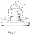
- Fig. 2 is an elevational view thereof.
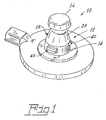
- a bulb 10 having a central stem 12 that includes a base 14, a summit 16, and an intermediate portion 18.
- a parabolic reflector 20 is positioned about the base 14 and has a first reflector surface 22 facing the summit 16. At least one light source 24 is positioned on the summit 16 for directing primary illumination toward the reflector surface 22 on the reflector 20. In a preferred embodiment of the invention a plurality of light sources 24 are employed to even the distribution of light and the light sources are red light emitting LEDs.
Landscapes
- Engineering & Computer Science (AREA)
- Physics & Mathematics (AREA)
- Microelectronics & Electronic Packaging (AREA)
- Optics & Photonics (AREA)
- General Engineering & Computer Science (AREA)
- Non-Portable Lighting Devices Or Systems Thereof (AREA)
Abstract
Description
Claims (10)
- A bulb comprising:a central stem including a base, a summit, and an intermediate portion;a reflector positioned about said base having a first reflector surface facing said summit;at least one light source on said summit for directing primary illumination toward said reflector surface on said reflector; andan optic associated with at least a part of said intermediate portion, said optic having a second reflector surface for directing secondary illumination toward said first reflector surface.
- The bulb of Claim 1 wherein said summit includes multiple light sources.
- The bulb of Claim 2 wherein said light sources are light emitting diodes.
- The bulb of Claim 2 wherein said reflector is parabolic.
- The bulb of Claim 2 wherein said central stem has an axis and said light sources are mounted normal to said axis.
- The bulb of Claim 5 wherein said optic is comprised of a wide frustum and a narrow frustum joined by a radius.
- The bulb of Claim 6 wherein said optic is an integral part of said stem.
- The bulb of Claim 6 wherein said optic is a separate part fitted over said stem.
- The bulb of Claim 8 wherein said optic is metallized plastic.
- A bulb comprising:a central stem including a base, a summit and an intermediate portion;at lease one light source on said summit for directing illumination toward said stem; andan optic associated with at least a part of said intermediate portion of said stem for reflectingat least a portion of said illumination emanating from said light source.
Applications Claiming Priority (4)
| Application Number | Priority Date | Filing Date | Title |
|---|---|---|---|
| US50744803P | 2003-09-30 | 2003-09-30 | |
| US507448P | 2003-09-30 | ||
| US846074 | 2004-05-14 | ||
| US10/846,074 US7052166B2 (en) | 2003-09-30 | 2004-05-14 | Light emitting diode optics |
Publications (2)
| Publication Number | Publication Date |
|---|---|
| EP1526330A2 true EP1526330A2 (en) | 2005-04-27 |
| EP1526330A3 EP1526330A3 (en) | 2007-07-04 |
Family
ID=34381357
Family Applications (1)
| Application Number | Title | Priority Date | Filing Date |
|---|---|---|---|
| EP04020086A Withdrawn EP1526330A3 (en) | 2003-09-30 | 2004-08-24 | Light emitting diode optics |
Country Status (3)
| Country | Link |
|---|---|
| US (1) | US7052166B2 (en) |
| EP (1) | EP1526330A3 (en) |
| CA (1) | CA2477649A1 (en) |
Families Citing this family (13)
| Publication number | Priority date | Publication date | Assignee | Title |
|---|---|---|---|---|
| USD586751S1 (en) * | 2004-04-22 | 2009-02-17 | Osram Sylvania, Inc. | Light emitting diode bulb connector |
| USD619964S1 (en) * | 2004-04-22 | 2010-07-20 | Osram Sylvania, Inc. | Light emitting diode bulb connector |
| USD610545S1 (en) * | 2004-04-22 | 2010-02-23 | Osram Sylvania, Inc. | Light emitting diode bulb connector |
| US7249877B2 (en) * | 2004-09-23 | 2007-07-31 | Osram Sylvania Inc. | Led lamp bulb assembly and reflector system |
| CN2821377Y (en) * | 2005-05-25 | 2006-09-27 | 钟根发 | Reflective light emitting diode lighting lamp |
| US7824076B2 (en) * | 2007-05-31 | 2010-11-02 | Koester George H | LED reflector lamp |
| WO2010005655A2 (en) | 2008-07-10 | 2010-01-14 | 3M Innovative Properties Company | Viscoelastic lightguide |
| CN102171593A (en) | 2008-08-08 | 2011-08-31 | 3M创新有限公司 | Light guide for controlling light with viscoelastic layer |
| USD624233S1 (en) * | 2009-11-27 | 2010-09-21 | Edison Opto Corporation | Lampwick of light emitting diode bulb |
| DE102010030296B4 (en) * | 2010-06-21 | 2012-11-22 | Osram Ag | Lamp with concave reflector and a projection for at least one light source |
| US20120293995A1 (en) * | 2011-05-19 | 2012-11-22 | Wybron, Inc. | Led light assembly and method for construction thereof |
| DE102013220876A1 (en) * | 2013-10-15 | 2015-04-16 | Trilux Medical Gmbh & Co. Kg | LED surgical light |
| CA3005802C (en) * | 2018-05-23 | 2021-01-12 | Xin Dong | Led lamp for vehicles |
Family Cites Families (6)
| Publication number | Priority date | Publication date | Assignee | Title |
|---|---|---|---|---|
| US5561346A (en) * | 1994-08-10 | 1996-10-01 | Byrne; David J. | LED lamp construction |
| TW507858U (en) * | 2001-07-23 | 2002-10-21 | Lin Chau Tang | Energy saving lighting device with high illumination |
| US6682211B2 (en) * | 2001-09-28 | 2004-01-27 | Osram Sylvania Inc. | Replaceable LED lamp capsule |
| US6641293B2 (en) * | 2001-10-31 | 2003-11-04 | Visteon Global Technologies, Inc. | Light shield with reflective inner surface |
| US6773138B2 (en) * | 2002-04-09 | 2004-08-10 | Osram Sylvania Inc. | Snap together automotive led lamp assembly |
| US7048412B2 (en) * | 2002-06-10 | 2006-05-23 | Lumileds Lighting U.S., Llc | Axial LED source |
-
2004
- 2004-05-14 US US10/846,074 patent/US7052166B2/en not_active Expired - Lifetime
- 2004-08-16 CA CA002477649A patent/CA2477649A1/en not_active Abandoned
- 2004-08-24 EP EP04020086A patent/EP1526330A3/en not_active Withdrawn
Also Published As
| Publication number | Publication date |
|---|---|
| US7052166B2 (en) | 2006-05-30 |
| US20050068772A1 (en) | 2005-03-31 |
| CA2477649A1 (en) | 2005-03-30 |
| EP1526330A3 (en) | 2007-07-04 |
Similar Documents
| Publication | Publication Date | Title |
|---|---|---|
| EP1452797B2 (en) | Illumination apparatus | |
| JP4708097B2 (en) | Light emitting diode lamp with light guide converging in a conical shape | |
| US7431486B2 (en) | LED assembly for rear lamps in an automobile | |
| US7625102B2 (en) | Lighting device | |
| US7654713B2 (en) | Vehicular lamp | |
| US9851066B2 (en) | Reflector signal lamp having a hidden light source | |
| US7052166B2 (en) | Light emitting diode optics | |
| US20170267163A1 (en) | Vehicle decorative lighting device and vehicle lamp | |
| JP6777432B2 (en) | Vehicle lighting | |
| JP2003229006A (en) | Lamp | |
| US20090207610A1 (en) | Combination rear lighting system | |
| US20100246203A1 (en) | System and method for exterior lighting of vehicles | |
| CN105318281B (en) | Laser optical system for a headlamp | |
| JP2020205147A (en) | Light guide and vehicle lamps | |
| KR200483320Y1 (en) | Lamp for vehicle | |
| KR20160054984A (en) | Lamp for vehicles | |
| US10107478B1 (en) | Light assembly | |
| US20040218399A1 (en) | Vehicle lighting device | |
| JP2000331508A (en) | LED lamp and vehicle lamp using the LED lamp as a light source | |
| JP2003249107A (en) | Beam light | |
| JP2023182555A (en) | Beam shaping waveguide for headlights | |
| JP2019071204A (en) | Vehicular lighting fixture | |
| US20050030759A1 (en) | Bifocal hyperbolic catadioptric collection system for an automotive lamp | |
| KR20170000496A (en) | An improved flat lamp structure | |
| KR20160012465A (en) | A head lamp for vehicles |
Legal Events
| Date | Code | Title | Description |
|---|---|---|---|
| PUAI | Public reference made under article 153(3) epc to a published international application that has entered the european phase |
Free format text: ORIGINAL CODE: 0009012 |
|
| AK | Designated contracting states |
Kind code of ref document: A2 Designated state(s): AT BE BG CH CY CZ DE DK EE ES FI FR GB GR HU IE IT LI LU MC NL PL PT RO SE SI SK TR |
|
| AX | Request for extension of the european patent |
Extension state: AL HR LT LV MK |
|
| PUAL | Search report despatched |
Free format text: ORIGINAL CODE: 0009013 |
|
| AK | Designated contracting states |
Kind code of ref document: A3 Designated state(s): AT BE BG CH CY CZ DE DK EE ES FI FR GB GR HU IE IT LI LU MC NL PL PT RO SE SI SK TR |
|
| AX | Request for extension of the european patent |
Extension state: AL HR LT LV MK |
|
| RIC1 | Information provided on ipc code assigned before grant |
Ipc: F21Y 101/02 20060101ALN20070530BHEP Ipc: F21V 7/00 20060101ALI20070530BHEP Ipc: F21K 7/00 20060101ALI20070530BHEP Ipc: F21S 8/10 20060101AFI20070530BHEP |
|
| 17P | Request for examination filed |
Effective date: 20070720 |
|
| 17Q | First examination report despatched |
Effective date: 20070827 |
|
| AKX | Designation fees paid |
Designated state(s): AT BE BG CH CY CZ DE DK EE ES FI FR GB GR HU IE IT LI LU MC NL PL PT RO SE SI SK TR |
|
| GRAP | Despatch of communication of intention to grant a patent |
Free format text: ORIGINAL CODE: EPIDOSNIGR1 |
|
| STAA | Information on the status of an ep patent application or granted ep patent |
Free format text: STATUS: THE APPLICATION IS DEEMED TO BE WITHDRAWN |
|
| 18D | Application deemed to be withdrawn |
Effective date: 20081115 |