US10791237B2 - Scanner - Google Patents
Scanner Download PDFInfo
- Publication number
- US10791237B2 US10791237B2 US16/572,631 US201916572631A US10791237B2 US 10791237 B2 US10791237 B2 US 10791237B2 US 201916572631 A US201916572631 A US 201916572631A US 10791237 B2 US10791237 B2 US 10791237B2
- Authority
- US
- United States
- Prior art keywords
- background
- calibration
- engaging portion
- roller
- section
- Prior art date
- Legal status (The legal status is an assumption and is not a legal conclusion. Google has not performed a legal analysis and makes no representation as to the accuracy of the status listed.)
- Active
Links
Images


Classifications
-
- H—ELECTRICITY
- H04—ELECTRIC COMMUNICATION TECHNIQUE
- H04N—PICTORIAL COMMUNICATION, e.g. TELEVISION
- H04N1/00—Scanning, transmission or reproduction of documents or the like, e.g. facsimile transmission; Details thereof
- H04N1/00567—Handling of original or reproduction media, e.g. cutting, separating, stacking
- H04N1/0057—Conveying sheets before or after scanning
- H04N1/00572—Conveying sheets before or after scanning with refeeding for double-sided scanning, e.g. using one scanning head for both sides of a sheet
-
- H—ELECTRICITY
- H04—ELECTRIC COMMUNICATION TECHNIQUE
- H04N—PICTORIAL COMMUNICATION, e.g. TELEVISION
- H04N1/00—Scanning, transmission or reproduction of documents or the like, e.g. facsimile transmission; Details thereof
- H04N1/00567—Handling of original or reproduction media, e.g. cutting, separating, stacking
- H04N1/0057—Conveying sheets before or after scanning
- H04N1/00588—Conveying sheets before or after scanning to the scanning position
-
- H—ELECTRICITY
- H04—ELECTRIC COMMUNICATION TECHNIQUE
- H04N—PICTORIAL COMMUNICATION, e.g. TELEVISION
- H04N1/00—Scanning, transmission or reproduction of documents or the like, e.g. facsimile transmission; Details thereof
- H04N1/00567—Handling of original or reproduction media, e.g. cutting, separating, stacking
- H04N1/0057—Conveying sheets before or after scanning
- H04N1/00591—Conveying sheets before or after scanning from the scanning position
-
- H—ELECTRICITY
- H04—ELECTRIC COMMUNICATION TECHNIQUE
- H04N—PICTORIAL COMMUNICATION, e.g. TELEVISION
- H04N1/00—Scanning, transmission or reproduction of documents or the like, e.g. facsimile transmission; Details thereof
- H04N1/00567—Handling of original or reproduction media, e.g. cutting, separating, stacking
- H04N1/0057—Conveying sheets before or after scanning
- H04N1/00599—Using specific components
- H04N1/00602—Feed rollers
-
- H—ELECTRICITY
- H04—ELECTRIC COMMUNICATION TECHNIQUE
- H04N—PICTORIAL COMMUNICATION, e.g. TELEVISION
- H04N1/00—Scanning, transmission or reproduction of documents or the like, e.g. facsimile transmission; Details thereof
- H04N1/00795—Reading arrangements
- H04N1/00798—Circuits or arrangements for the control thereof, e.g. using a programmed control device or according to a measured quantity
-
- H—ELECTRICITY
- H04—ELECTRIC COMMUNICATION TECHNIQUE
- H04N—PICTORIAL COMMUNICATION, e.g. TELEVISION
- H04N1/00—Scanning, transmission or reproduction of documents or the like, e.g. facsimile transmission; Details thereof
- H04N1/04—Scanning arrangements, i.e. arrangements for the displacement of active reading or reproducing elements relative to the original or reproducing medium, or vice versa
- H04N1/12—Scanning arrangements, i.e. arrangements for the displacement of active reading or reproducing elements relative to the original or reproducing medium, or vice versa using the sheet-feed movement or the medium-advance or the drum-rotation movement as the slow scanning component, e.g. arrangements for the main-scanning
- H04N1/121—Feeding arrangements
- H04N1/125—Feeding arrangements the sheet feeding apparatus serving an auxiliary function, e.g. as a white reference
-
- H—ELECTRICITY
- H04—ELECTRIC COMMUNICATION TECHNIQUE
- H04N—PICTORIAL COMMUNICATION, e.g. TELEVISION
- H04N2201/00—Indexing scheme relating to scanning, transmission or reproduction of documents or the like, and to details thereof
- H04N2201/04—Scanning arrangements
- H04N2201/0402—Arrangements not specific to a particular one of the scanning methods covered by groups H04N1/04 - H04N1/207
- H04N2201/0432—Adjusting the orientation of the scanning elements relative to the scanned sheet, e.g. changing from longitudinal to lateral scanning
Definitions
- the invention relates to a scanner, and particularly relates to a scanner capable of providing a black background, a white background and a calibration section.
- a background and calibration roller is generally configured at a position corresponding to a scanning module inside a scanner.
- the current background and calibration roller is configured with a single background section and a single calibration section on different parts of an outer surface thereof.
- the background section of the background and calibration roller is configured to increase scanning quality during a scanning process.
- the calibration section of the background and calibration roller is used for calibration of the scanning module before the scanning.
- the current scanner may adopt a rotation mechanism to rotate the background and calibration roller between two positions, so as to select the background section or the calibration section to face towards the scanning module.
- the rotation mechanism of the conventional scanner can only rotate the background and calibration roller between two positions (the background section and the calibration section), so that only the single background section may be set.
- a black background section and a white background section may provide different effects. If the numbers of the background sections or the calibration sections on the background and calibration roller are to be increased, the background and calibration roller is required to be positioned at different sections, which greatly increases difficulty of the mechanism.
- the invention is directed to a scanner provided with a background and calibration roller having a black background section, a white background section and at least one calibration section.
- the invention provides a scanner including a paper feeding roller set, a paper exporting roller set, a scanning module, a background and calibration roller, a main driving assembly, a first sleeve, a torque limiter and a stop-driving assembly.
- the scanning module is disposed between the paper feeding roller set and the paper exporting roller set.
- the background and calibration roller is disposed side by side next to the scanning module, and the background and calibration roller has a first end and a second end opposite to each other, and includes a black background section, a white background section and at least one calibration section located between the first end and the second end.
- the main driving assembly includes a main power source and a transmission set linked to the main power source.
- the paper feeding roller set and the paper exporting roller set are linked to the transmission set.
- the first sleeve sleeves the first end of the background and calibration roller and is linked to the transmission set.
- the torque limiter is disposed between the first end of the background and calibration roller and the first sleeve and contacts the first end and the first sleeve, and a torque of the first sleeve is adapted to be transmitted to the background and calibration roller through the torque limiter.
- the stop-driving assembly is selectively abutting against two portions of the background and calibration roller, so as to make the black background section or the white background section of the background and calibration roller facing towards the scanning module.
- the main driving assembly of the scanner drives the background and calibration roller to rotate by means of the first sleeve and the torque limiter, and the third engaging portion of the stop-driving assembly is selectively engaged with the second sleeve, such as the first engaging portion, the second engaging portion or none of the above, so as to make the black background section of the background and calibration roller or the white background section of the background and calibration roller facing towards the scanning module, and therefore meets different requirements.
- FIG. 1 is an internal side view of a scanner according to an embodiment of the invention.
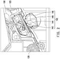
- FIG. 2 is a partial enlarged view of FIG. 1 .
- FIG. 3 is a partial enlarged view of a situation that a black background section of a background and calibration roller of FIG. 1 faces towards the scanning module.
- FIG. 4 is a partial enlarged view of a situation that a calibration section of the background and calibration roller of FIG. 1 faces towards the scanning module.
- FIG. 5 is a schematic diagram of a part of components of the scanner of FIG. 1 .
- FIG. 6 is a partial cross-sectional view of a first sleeve, a torque limiter and a background and calibration roller of the scanner of FIG. 1 .
- FIG. 7 to FIG. 9 are schematic diagrams of an engaging process of a stop-driving assembly and a second sleeve of the scanner of FIG. 1 .
- FIG. 10 is a schematic diagram of a stop-driving assembly of a scanner according to another embodiment of the invention.
- FIG. 11 is a schematic diagram of a background and calibration roller and a casing of the scanner of FIG. 1 .
- FIG. 12 is a partial enlarged view of FIG. 11 .
- FIG. 13 is a partial schematic diagram of a background and calibration roller according to another embodiment of the invention.
- FIG. 14A is a partial schematic diagram of the stop-driving assembly abutted against a surface of a positioning member of the background and calibration roller of FIG. 13 .
- FIG. 14B is a partial enlarged view of a situation that a black background section of the background and calibration roller of FIG. 13 faces towards the scanning module.
- FIG. 15A is a partial schematic diagram of the stop-driving assembly engaged with the positioning member of the background and calibration roller of FIG. 13 .
- FIG. 15B is a partial enlarged view of a situation that a white background section of the background and calibration roller of FIG. 13 faces towards the scanning module.
- FIG. 16A is a partial schematic diagram of the stop-driving assembly not abutted against or engaged with the positioning member of the background and calibration roller of FIG. 13 .
- FIG. 16B is a partial enlarged view of a situation that a calibration section of the background and calibration roller of FIG. 13 faces towards the scanning module.
- FIG. 1 is an internal side view of a scanner according to an embodiment of the invention.
- the scanner 100 of the embodiment is, for example, a Multi-Function Printer (MFP) with printing and scanning functions.
- MFP Multi-Function Printer
- the type of the scanner 100 is not limited thereto.
- the scanner 100 has an upper portion and a lower portion.
- the lower portion of the scanner 100 includes a scanning module 132 (i.e., lower scanner module 132 ) capable of moving back and forth from the left to the right of FIG. 1 so as to provide the printing and scanning functions.
- a scanning module 132 i.e., lower scanner module 132
- the upper portion of the scanner 100 has a channel 127 , and a plurality of rollers (including a paper feeding roller set 120 and a paper exporting roller set 125 ) is disposed beside the channel 127 , and a paper (not shown) may be pushed by theses rollers to pass through the channel 127 to complete scanning.
- the upper portion of the scanner 100 includes a scanning module 130 (i.e., upper scanner module 130 ) and a background and calibration roller 140 located beside the upper scanning module 130 .
- the background and calibration roller 140 of the scanner 100 may provide with a plurality of background sections and calibration sections, such that the upper scanning module 130 may have good scanning quality, which is described in detail below.
- FIG. 2 is a partial enlarged view of FIG. 1 .
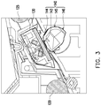
- FIG. 3 is a partial enlarged view of a situation that a black background section of the background and calibration roller of FIG. 1 faces towards the scanning module.
- FIG. 4 is a partial enlarged view of a situation that a calibration section of the background and calibration roller of FIG. 1 faces towards the scanning module.
- the background and calibration roller 140 of the scanner 100 includes a black background section 143 , a white background section 144 and at least one calibration section, where locations of the black background section 143 and the white background section 144 may be exchanged.
- the at least one calibration section includes a white calibration section 145 and a black calibration section 146 , where locations of the white calibration section 145 and the black calibration section 146 may be exchanged.
- the background and calibration roller 140 of the embodiment includes four sections. The four sections are respectively located at different parts on an outer surface of the background and calibration roller 140 . According to FIG. 2 to FIG. 4 , it is known that the background and calibration roller 140 may be rotated relative to the scanning module 130 to make different sections to face towards the scanning module 130 , so as to meet different requirements.
- the at least calibration section may also only include one white calibration section 145 or one black calibration section 146 .
- the user may use a white background to fade an image on the back of the paper.
- the background and calibration roller 140 is rotated and fixed to a position where the white background section 144 faces towards the scanning module 130 .
- the black background increases a boundary contrast when scanning a white paper.
- the background and calibration roller 140 is rotated and fixed to a position where the black background section 143 faces towards the scanning module 130 .
- the white calibration section 145 and the black calibration section 146 may be provided to the scanning module 130 to calibrate a white color and a black color before scanning.
- the background and calibration roller 140 is rotated and fixed to a position where the black calibration section 146 faces towards the scanning module 130 , and then the background and calibration roller 140 is rotated back to the black background section 143 or the white background section 144 . Since the background and calibration roller 140 of the embodiment has the aforementioned four sections, the image output by the scanning module 130 may have better quality.
- FIG. 5 is a schematic diagram of a part of components of the scanner of FIG. 1 .
- FIG. 6 is a partial cross-sectional view of a first sleeve, a torque limiter and a background and calibration roller of the scanner of FIG. 1 .
- the scanner 100 of the embodiment includes a main driving assembly 150 , a first sleeve 160 , a torque limiter 165 ( FIG. 6 ), a second sleeve 170 and a stop-driving assembly 180 .
- the main driving assembly 150 includes a main power source 152 and a transmission set 154 linked to the main power source 152 .
- the main power source 152 is, for example, a motor
- the transmission set 154 is, for example, a combination of gears and pulleys, but the types of the main power source 152 and the transmission set 154 are not limited thereto.
- the paper feeding roller set 120 ( FIG. 1 ) and the paper exporting roller set 125 ( FIG. 1 ) of the scanner 100 are linked to the transmission set 154 .
- the main driving assembly 150 may be used for simultaneously driving the paper feeding roller set 120 , the paper exporting roller set 125 and the background and calibration roller 140 . In this way, the scanner 100 is unnecessary to configure an additional driving assembly to rotate the background and calibration roller 140 , such that a volume of the mechanism and the number of the components are decreased accordingly.
- the form of the main driving assembly 150 is not limited thereto.
- the background and calibration roller 140 is disposed side by side next to the scanning module, and the background and calibration roller 140 has a first end 141 and a second end 142 opposite to each other.
- the first sleeve 160 sleeves the first end 141 of the background and calibration roller 140 and is linked to the transmission set 154 .
- the first sleeve 160 includes an external gear 162 meshed with a gear of the transmission set 154 .
- the first sleeve 160 may also be linked to the transmission set 154 through a belt, and the connection method is not limited by the invention.
- the torque limiter 165 is located between the first end 141 of the background and calibration roller 140 and the first sleeve 160 and contacts the first end 141 and the first sleeve 160 .
- the torque limiter 165 includes a spring, a first end of the spring contacts an inner surface 164 of the first sleeve 160 , and another end of the spring contacts a surface 148 of the background and calibration roller 140 at the first end 141 , such that a friction exists between the spring and the inner surface 164 of the first sleeve 160 and between the spring and the surface 148 .
- a torque of the first sleeve 160 is adapted to be transmitted to the background and calibration roller 140 through the torque limiter 165 .
- the first sleeve 160 may drive the background and calibration roller 140 to rotate through the torque limiter 165 .
- the torque limiter 165 may also be a leaf spring, and the type of the torque limiter 165 is not limited by the invention.
- the second sleeve 170 is fixed to the second end 142 of the background and calibration roller 140 , and includes a first engaging portion 172 and a second engaging portion 174 .
- the stop-driving assembly 180 is located beside the second sleeve 170 and includes a secondary power source 182 and a third engaging portion 184 linked to the secondary power source 182 , and the stop-driving assembly 180 is a stop device used for controlling a stop position of the second sleeve 170 .
- the secondary power source 182 is adapted to make the third engaging portion 184 to selectively engage or not engage with one of the first engaging portion 172 and the second engaging portion 174 , so as to make the black background section 143 , the white background section 144 , the white calibration section 145 or the black calibration section 146 of the background and calibration roller 140 to face towards the scanning module 130 .
- the second sleeve 170 is, for example, a latch roller, but the type of the second sleeve 170 is not limited thereto.
- FIG. 7 to FIG. 9 are schematic diagrams of an engaging process of the stop-driving assembly and the second sleeve of the scanner of FIG. 1 .
- the secondary power source 182 is, for example, an electromagnetic valve
- the third engaging portion 184 is, for example, a magnetic member.
- the third engaging portion 184 of the stop-driving member 180 is adapted to be engaged to the first engaging portion 172 of the second sleeve 170 .
- the main driving assembly 150 operates to sequentially drive the first sleeve 160 , the background and calibration roller 140 and the second sleeve 170 , and the third engaging portion 184 of the stop-driving assembly 180 may be engaged to the first engaging portion 172 of the second sleeve 170 , such that the black background section 143 of the background and calibration roller 140 faces towards the scanning module 130 .
- the secondary power source 182 When other section is selected to face towards the scanning module 130 , the secondary power source 182 is activated to attract the third engaging portion 184 , as shown in FIG. 8 , and the third engaging portion 184 is moved upwards to release a fixing relationship with the first engaging portion 172 .
- the second engaging portion 174 of the second sleeve 170 driven by the main driving assembly 150 may be rotated to a position corresponding to the third engaging portion 184 .
- the secondary power source 182 may stop operating, and the third engaging portion 184 is not magnetically attracted and restored to an original position, and is engaged to the second engaging portion 174 .
- the white background section of the background and calibration roller 140 faces towards the scanning module 130 .
- the main driving assembly 150 since the main driving assembly 150 is used for driving the paper feeding roller set 120 and the paper exporting roller set 125 , the main driving assembly 150 continuously operates, but the background and calibration roller 140 is required to be rotated to a specific position for fixing.
- the torque limiter 165 is specifically configured between the first sleeve 160 and the background and calibration roller 140 , and the third engaging portion 184 is selectively engaged with the first engaging portion 172 or the second engaging portion 174 , such that the background and calibration roller 140 may be rotated to a specific position for fixing.
- the background and calibration roller 140 is not limited, and the main driving assembly 150 operates to sequentially drive the first sleeve 160 , the torque limiter 165 and the background and calibration roller 140 to rotate.
- the third engaging portion 184 of the stop-driving assembly 180 is engaged with one of the first engaging portion 172 and the second engaging portion 174 of the second sleeve 170 , such that the background and calibration roller 140 is accordingly fixed.
- the operation of the main driving assembly 150 may drive the first sleeve, but since the background and calibration roller 140 is fixed, the friction between the torque limiter 165 and the surface 148 of the background and calibration roller 140 is not enough to drive the background and calibration roller 140 to rotate, the first sleeve presents an idle state.
- the main driving assembly 150 when the main driving assembly 150 operates, the first sleeve 160 is rotated, but the background and calibration roller 140 does not follow the rotation and stays at a specific position. In this way, the black background section 143 or the white background section 144 of the background and calibration roller 140 may face towards the scanning module 130 .
- the scanner 100 performs black calibration or white calibration
- the two sections may face towards the scanning module 130 and rotate, so that the main driving assembly 150 is only required to rotate the black calibration section 146 or the white calibration section 145 of the background and calibration roller 140 to face towards the scanning module 130 without fixing the background and calibration roller 140 .
- the third engaging portion 184 is not engaged with the first engaging portion 172 or the second engaging portion 174 .
- the second sleeve 170 and the background and calibration roller 140 are driven synchronously, in other embodiments, the second sleeve 170 and the background and calibration roller 140 may also be formed integrally, i.e. the background and calibration roller 140 has the mechanical characteristics of the blocked function of the second sleeve 170 .
- the scanner 100 since the scanner 100 adopts the main driving assembly 150 originally used for driving the paper feeding roller set 120 and the paper exporting roller set 125 to serve as the driving assembly for driving the background and calibration roller 140 , the scanner 100 is unnecessary to additionally configure a driving assembly for driving the background and calibration roller 140 .
- the scanner 100 of the embodiment is only required to add a set of stop-driving assembly 180 to selectively fix the second sleeve 170 , and the background and calibration roller 140 may be positioned to a plurality of positions, such that the background and calibration roller 140 may have the black background section or the white background section to provide the scanner 100 with better scanning quality.
- the type of the stop-driving assembly 180 is not limited thereto.
- FIG. 10 is a schematic diagram of a stop-driving assembly of a scanner according to another embodiment of the invention.
- the secondary power source 182 a includes a motor
- the stop-driving assembly 180 a further includes a gear 186 connected to the motor
- the third engaging portion 184 includes a gear rack 185 meshed with the gear 186 .
- the motor may drive the gear 186 to rotate, so as to drive the gear rack 185 to move up and down, so that the third engaging portion 184 may be engaged or not engaged with the first engaging portion 172 or the second engaging portion 174 .
- FIG. 11 is a schematic diagram of a background and calibration roller and a casing of the scanner of FIG. 1 .
- FIG. 12 is a partial enlarged view of FIG. 11 .
- the scanner 100 further includes a casing 110 , and the background and calibration roller 140 is rotatably disposed in the casing 110 .
- the background and calibration roller 140 includes a stop block 147
- the casing 110 includes a first stop wall 112 and a second stop wall 114 located on a rotating path of the stop block 147 .
- the first stop wall 112 and the second stop wall 114 are used for defining a rotating range of the background and calibration roller 140 to avoid excessive rotation of the background and calibration roller 140 .
- a rotating range of the stop block 147 between the first stop wall 112 and the second stop wall 114 is, for example, the rotating range of the background and calibration roller 140 shown in FIG. 3 to FIG. 4 .
- the scanning module 130 may then start the calibration.
- the scanning module 130 may radially scan the black calibration section 146 or the white calibration section 145 .
- the black calibration section 146 of the background and calibration roller 140 may be first turned to the scanning module 130 from a boundary of the black calibration section 146 and the white calibration section 145 . Then, the background and calibration roller 140 is rotated while the scanning module 130 performs scanning until the stop block 147 is stopped by the second stop wall 114 .
- FIG. 13 is a partial schematic diagram of a background and calibration roller according to another embodiment of the invention.
- a main difference between the background and calibration roller 140 of FIG. 5 and the background and calibration roller 140 b is that, in FIG. 5 , the second sleeve 170 is fixed to the second end 142 of the background and calibration roller 140 , and includes the first engaging portion 172 and the second engaging portion 174 for being fixed to different positions.
- the background and calibration roller 140 b includes a positioning member 149 for being fixed to different positions such that the second sleeve 170 in FIG. 5 can be omitted.
- the positioning member 149 is integrated with the background and calibration roller 140 b .
- the positioning member 149 can be manufactured first and then be fixed to the background and calibration roller 140 b .
- the positioning method of the background and calibration roller 140 b is not limited thereto.
- FIG. 14A is a partial schematic diagram of the stop-driving assembly abutted against a surface of a positioning member of the background and calibration roller of FIG. 13 .
- FIG. 14B is a partial enlarged view of a situation that a black background section of the background and calibration roller of FIG. 13 faces towards the scanning module.
- the stop-driving assembly 180 b is located beside the positioning member 149 of the background and calibration roller 140 b and includes a secondary power source 182 b (e.g.
- the secondary power source 182 b is adapted to make the third engaging portion 184 b to move by magnetization so as to selectively abutted against a first surface 1491 (e.g. an inclined surface) or a second surface 1492 of the positioning member 149 , so as to make the black background section 143 , the white background section 144 , the white calibration section 145 or the black calibration section 146 of the background and calibration roller 140 b to face towards the scanning module 130 .
- a first surface 1491 e.g. an inclined surface
- a second surface 1492 of the positioning member 149 so as to make the black background section 143 , the white background section 144 , the white calibration section 145 or the black calibration section 146 of the background and calibration roller 140 b to face towards the scanning module 130 .
- FIG. 15A is a partial schematic diagram of the stop-driving assembly engaged with the positioning member of the background and calibration roller of FIG. 13 .
- FIG. 15B is a partial enlarged view of a situation that a white background section of the background and calibration roller of FIG. 13 faces towards the scanning module.
- the third engaging portion 184 b is moved to abutted against the second surface 1492 of the positioning member 149 .
- the background and calibration roller 140 b does not rotate, the white calibration section 145 of the background and calibration roller 140 b faces towards the scanning module 130 .
- FIG. 16A is a partial schematic diagram of the stop-driving assembly not abutted against or engaged with the positioning member of the background and calibration roller of FIG. 13 .
- FIG. 16B is a partial enlarged view of a situation that a calibration section of the background and calibration roller of FIG. 13 faces towards the scanning module. Referring to FIG. 16A and FIG. 16B , when one of the white calibration section 145 and the black calibration section 146 of the background and calibration roller 140 b faces towards the scanning module 130 , the third engaging portion 184 b is not abutted against the first surface 1491 and the second surface 1492 of the positioning member 149 . In the white calibration procedure or the black calibration procedure, the scanning module 130 may radially scan the white calibration section 145 or the black calibration section 146 .
- the white calibration section 145 of the background and calibration roller 140 b faces towards the scanning module 130 .
- the white calibration section 145 of the background and calibration roller 140 may be first turned to the scanning module 130 from a boundary of the white background section 144 and the white calibration section 145 . Then, the background and calibration roller 140 is rotated while the scanning module 130 performs scanning.
- the scanner of the invention uses the main driving assembly, the first sleeve and the torque limiter to drive the background and calibration roller to rotate, and the third engaging portion of the stop-driving assembly is selectively engaged or not engaged with the first engaging portion or the second engaging portion, so as to make the black background section or the white background section of the background and calibration roller facing towards the scanning module, and meet different requirements.
- the main driving assembly may be the driving assembly originally driving the paper feeding roller set and the paper exporting roller set, and the scanner is unnecessary to additionally configure a driving assembly for driving the background and calibration roller, so as to simplify the mechanism.
Landscapes
- Engineering & Computer Science (AREA)
- Multimedia (AREA)
- Signal Processing (AREA)
- Facsimile Scanning Arrangements (AREA)
- Facsimiles In General (AREA)
Abstract
Description
Claims (14)
Applications Claiming Priority (3)
| Application Number | Priority Date | Filing Date | Title |
|---|---|---|---|
| CN201811129871.8 | 2018-09-27 | ||
| CN201811129871 | 2018-09-27 | ||
| CN201811129871.8A CN110958356B (en) | 2018-09-27 | 2018-09-27 | Scanner |
Publications (2)
| Publication Number | Publication Date |
|---|---|
| US20200106912A1 US20200106912A1 (en) | 2020-04-02 |
| US10791237B2 true US10791237B2 (en) | 2020-09-29 |
Family
ID=69946315
Family Applications (1)
| Application Number | Title | Priority Date | Filing Date |
|---|---|---|---|
| US16/572,631 Active US10791237B2 (en) | 2018-09-27 | 2019-09-17 | Scanner |
Country Status (2)
| Country | Link |
|---|---|
| US (1) | US10791237B2 (en) |
| CN (1) | CN110958356B (en) |
Families Citing this family (1)
| Publication number | Priority date | Publication date | Assignee | Title |
|---|---|---|---|---|
| TWI748751B (en) * | 2020-11-17 | 2021-12-01 | 虹光精密工業股份有限公司 | Document scanning device with detachable presser assembly |
Citations (10)
| Publication number | Priority date | Publication date | Assignee | Title |
|---|---|---|---|---|
| US20080239416A1 (en) * | 2007-03-29 | 2008-10-02 | Canon Denshi Kabushiki Kaisha | Image reading apparatus and control method thereof |
| US20100085616A1 (en) * | 2008-10-03 | 2010-04-08 | Konica Minolta Business Technologies, Inc. | Image reading apparatus |
| US20110199653A1 (en) * | 2010-02-15 | 2011-08-18 | Konica Minolta Business Technologies, Inc. | Image reading apparatus |
| US20120008997A1 (en) * | 2010-07-08 | 2012-01-12 | Konica Minolta Business Technologies, Inc. | Sheet feeding device, automatic sheet transfer device and image forming device |
| US20140260739A1 (en) * | 2013-03-15 | 2014-09-18 | Foxlink Image Technology Co., Ltd. | Transmission device for automatic document feeder |
| US8998208B1 (en) * | 2013-11-25 | 2015-04-07 | Foxlink Image Technology Co., Ltd. | Transmission device of automatic document feeder |
| TWM503039U (en) | 2014-11-17 | 2015-06-11 | Lite On Technology Corp | Paper-feeding scanning device with correction function |
| CN106464771A (en) | 2014-04-29 | 2017-02-22 | 惠普发展公司,有限责任合伙企业 | Scanner with a background |
| TW201811649A (en) | 2016-09-02 | 2018-04-01 | 光寶電子(廣州)有限公司 | Active paper pickup and separation mechanism |
| US20180109693A1 (en) * | 2016-10-19 | 2018-04-19 | Konica Minolta, Inc. | Image reading apparatus and image forming apparatus |
Family Cites Families (5)
| Publication number | Priority date | Publication date | Assignee | Title |
|---|---|---|---|---|
| KR100420051B1 (en) * | 2000-06-26 | 2004-02-25 | 가부시기가이샤 산교세이기 세이사꾸쇼 | Rotation suppressing mechanism and geared motor |
| JP4163537B2 (en) * | 2003-03-12 | 2008-10-08 | 株式会社リコー | Image reading device |
| CN101350879B (en) * | 2008-08-18 | 2011-07-06 | 山东山大鸥玛软件有限公司 | Apparatus for replacing background of picture scanning equipment |
| JP6084272B1 (en) * | 2015-11-18 | 2017-02-22 | 株式会社Pfu | Image reading device |
| JP6822169B2 (en) * | 2017-01-24 | 2021-01-27 | セイコーエプソン株式会社 | Scanners and how to manufacture scanners |
-
2018
- 2018-09-27 CN CN201811129871.8A patent/CN110958356B/en active Active
-
2019
- 2019-09-17 US US16/572,631 patent/US10791237B2/en active Active
Patent Citations (10)
| Publication number | Priority date | Publication date | Assignee | Title |
|---|---|---|---|---|
| US20080239416A1 (en) * | 2007-03-29 | 2008-10-02 | Canon Denshi Kabushiki Kaisha | Image reading apparatus and control method thereof |
| US20100085616A1 (en) * | 2008-10-03 | 2010-04-08 | Konica Minolta Business Technologies, Inc. | Image reading apparatus |
| US20110199653A1 (en) * | 2010-02-15 | 2011-08-18 | Konica Minolta Business Technologies, Inc. | Image reading apparatus |
| US20120008997A1 (en) * | 2010-07-08 | 2012-01-12 | Konica Minolta Business Technologies, Inc. | Sheet feeding device, automatic sheet transfer device and image forming device |
| US20140260739A1 (en) * | 2013-03-15 | 2014-09-18 | Foxlink Image Technology Co., Ltd. | Transmission device for automatic document feeder |
| US8998208B1 (en) * | 2013-11-25 | 2015-04-07 | Foxlink Image Technology Co., Ltd. | Transmission device of automatic document feeder |
| CN106464771A (en) | 2014-04-29 | 2017-02-22 | 惠普发展公司,有限责任合伙企业 | Scanner with a background |
| TWM503039U (en) | 2014-11-17 | 2015-06-11 | Lite On Technology Corp | Paper-feeding scanning device with correction function |
| TW201811649A (en) | 2016-09-02 | 2018-04-01 | 光寶電子(廣州)有限公司 | Active paper pickup and separation mechanism |
| US20180109693A1 (en) * | 2016-10-19 | 2018-04-19 | Konica Minolta, Inc. | Image reading apparatus and image forming apparatus |
Also Published As
| Publication number | Publication date |
|---|---|
| US20200106912A1 (en) | 2020-04-02 |
| CN110958356A (en) | 2020-04-03 |
| CN110958356B (en) | 2022-01-25 |
Similar Documents
| Publication | Publication Date | Title |
|---|---|---|
| JP3810643B2 (en) | Image reading device | |
| US5862446A (en) | Drive switching mechanism for use in image input apparatus | |
| US8369746B2 (en) | Clutch mechanism and processing device and image forming apparatus comprising the clutch mechanism | |
| US10691003B2 (en) | Projection type image display apparatus | |
| US20130329265A1 (en) | Image reading device and image forming apparatus | |
| JP2008185709A (en) | Projecting optical system and unit, and projection display | |
| JP2017088361A (en) | Automatic document feeder, image reading apparatus, and image forming apparatus | |
| US10791237B2 (en) | Scanner | |
| JP2016128703A (en) | Rotary drive transmission device and image forming apparatus including the same | |
| US8934802B2 (en) | Image forming apparatus | |
| US7903997B2 (en) | Coupling apparatus and image forming apparatus employing the same | |
| US8189253B2 (en) | Shutter device and drive method | |
| US6942213B2 (en) | Duplex scanning device | |
| US8672318B2 (en) | Automatic document conveying device and image forming apparatus including the same | |
| JP2014033390A (en) | Image reading device | |
| TWI670183B (en) | scanner | |
| JP7151783B2 (en) | Image reading device, image forming device | |
| JP2005292532A (en) | Light quantity adjustment apparatus and projector using the same | |
| US9546071B1 (en) | Sheet transport device, image reading device, and image forming apparatus | |
| JP2006078787A (en) | Projector apparatus | |
| JP3839214B2 (en) | Image reading apparatus, automatic document feeder, and image forming system | |
| CN106973182B (en) | Driving device, image read-out and image forming apparatus | |
| JP6604066B2 (en) | Sheet conveying apparatus, image reading apparatus, and image forming apparatus | |
| KR100574507B1 (en) | Automatic skew adjusting device, image forming device having same and skew adjusting method | |
| JP5439326B2 (en) | Sheet material feeding apparatus and image forming apparatus |
Legal Events
| Date | Code | Title | Description |
|---|---|---|---|
| AS | Assignment |
Owner name: LITE-ON ELECTRONICS (GUANGZHOU) LIMITED, CHINA Free format text: ASSIGNMENT OF ASSIGNORS INTEREST;ASSIGNOR:HUNG, CHUN-TSENG;REEL/FRAME:050394/0195 Effective date: 20190912 Owner name: LITE-ON TECHNOLOGY CORPORATION, TAIWAN Free format text: ASSIGNMENT OF ASSIGNORS INTEREST;ASSIGNOR:HUNG, CHUN-TSENG;REEL/FRAME:050394/0195 Effective date: 20190912 |
|
| FEPP | Fee payment procedure |
Free format text: ENTITY STATUS SET TO UNDISCOUNTED (ORIGINAL EVENT CODE: BIG.); ENTITY STATUS OF PATENT OWNER: LARGE ENTITY |
|
| STPP | Information on status: patent application and granting procedure in general |
Free format text: NOTICE OF ALLOWANCE MAILED -- APPLICATION RECEIVED IN OFFICE OF PUBLICATIONS |
|
| STCF | Information on status: patent grant |
Free format text: PATENTED CASE |
|
| AS | Assignment |
Owner name: GUANGZHOU LUXVISIONS INNOVATION TECHNOLOGY LIMITED, CHINA Free format text: NUNC PRO TUNC ASSIGNMENT;ASSIGNORS:LITE-ON ELECTRONICS (GUANGZHOU) LIMITED;LITE-ON TECHNOLOGY CORPORATION;REEL/FRAME:063761/0277 Effective date: 20230407 |
|
| MAFP | Maintenance fee payment |
Free format text: PAYMENT OF MAINTENANCE FEE, 4TH YEAR, LARGE ENTITY (ORIGINAL EVENT CODE: M1551); ENTITY STATUS OF PATENT OWNER: LARGE ENTITY Year of fee payment: 4 |