US10782499B2 - Cable storage arrangement - Google Patents
Cable storage arrangement Download PDFInfo
- Publication number
- US10782499B2 US10782499B2 US15/567,923 US201615567923A US10782499B2 US 10782499 B2 US10782499 B2 US 10782499B2 US 201615567923 A US201615567923 A US 201615567923A US 10782499 B2 US10782499 B2 US 10782499B2
- Authority
- US
- United States
- Prior art keywords
- cable
- cover
- wall
- spool structure
- storage arrangement
- Prior art date
- Legal status (The legal status is an assumption and is not a legal conclusion. Google has not performed a legal analysis and makes no representation as to the accuracy of the status listed.)
- Active
Links
- 239000000835 fiber Substances 0.000 claims abstract description 40
- 238000005452 bending Methods 0.000 claims description 3
- 230000037361 pathway Effects 0.000 claims 1
- 230000003287 optical effect Effects 0.000 description 19
- 238000004804 winding Methods 0.000 description 9
- 230000000717 retained effect Effects 0.000 description 3
- 239000000853 adhesive Substances 0.000 description 2
- 230000001070 adhesive effect Effects 0.000 description 2
- 230000004927 fusion Effects 0.000 description 2
- 230000004048 modification Effects 0.000 description 2
- 238000012986 modification Methods 0.000 description 2
- 239000013307 optical fiber Substances 0.000 description 2
- 230000007704 transition Effects 0.000 description 2
- 230000009471 action Effects 0.000 description 1
- 230000008901 benefit Effects 0.000 description 1
- 238000004891 communication Methods 0.000 description 1
- 238000009434 installation Methods 0.000 description 1
- 238000000465 moulding Methods 0.000 description 1
- 230000007935 neutral effect Effects 0.000 description 1
- 230000005693 optoelectronics Effects 0.000 description 1
- 230000001681 protective effect Effects 0.000 description 1
Images


Classifications
-
- G—PHYSICS
- G02—OPTICS
- G02B—OPTICAL ELEMENTS, SYSTEMS OR APPARATUS
- G02B6/00—Light guides; Structural details of arrangements comprising light guides and other optical elements, e.g. couplings
- G02B6/44—Mechanical structures for providing tensile strength and external protection for fibres, e.g. optical transmission cables
- G02B6/4439—Auxiliary devices
- G02B6/4457—Bobbins; Reels
-
- G—PHYSICS
- G02—OPTICS
- G02B—OPTICAL ELEMENTS, SYSTEMS OR APPARATUS
- G02B6/00—Light guides; Structural details of arrangements comprising light guides and other optical elements, e.g. couplings
- G02B6/24—Coupling light guides
- G02B6/36—Mechanical coupling means
- G02B6/38—Mechanical coupling means having fibre to fibre mating means
- G02B6/3807—Dismountable connectors, i.e. comprising plugs
- G02B6/3897—Connectors fixed to housings, casing, frames or circuit boards
-
- G02B6/4466—
-
- G—PHYSICS
- G02—OPTICS
- G02B—OPTICAL ELEMENTS, SYSTEMS OR APPARATUS
- G02B6/00—Light guides; Structural details of arrangements comprising light guides and other optical elements, e.g. couplings
- G02B6/46—Processes or apparatus adapted for installing or repairing optical fibres or optical cables
- G02B6/47—Installation in buildings
- G02B6/475—Mechanical aspects of installing cables in ducts or the like for buildings
-
- G—PHYSICS
- G02—OPTICS
- G02B—OPTICAL ELEMENTS, SYSTEMS OR APPARATUS
- G02B6/00—Light guides; Structural details of arrangements comprising light guides and other optical elements, e.g. couplings
- G02B6/44—Mechanical structures for providing tensile strength and external protection for fibres, e.g. optical transmission cables
- G02B6/4439—Auxiliary devices
- G02B6/4471—Terminating devices ; Cable clamps
Definitions
- Fiber optic distribution cables are routed from a central office to extended areas.
- the distribution cable is routed from the central office to a large fiber distribution hub.
- the distribution cable is split out into a number of individual fiber optic cables at the fiber distribution hub.
- the individual fiber optic cables are then each routed to a wall-mount box (e.g., a floor box) located at the multiple dwelling unit. Subscriber cables are routed from the wall-mount box to one or more residences.
- the large fiber distribution hub is located remote from the wall-mount box.
- the fiber distribution hub splits out a number of multi-fiber distribution cables and feeds a number of wall-mount boxes.
- a cable storage arrangement or wall outlet including a base structure, a non-rotatable spool structure extending from the base structure, a length of cable wound about the spool structure, and a cover rotatably mounted to the base structure and/or spool structure.
- the spool structure includes a hub portion extending between a first wall and a second wall.
- the length of cable extends between first and second ends, each of which can be provided with a fiber optic connector. At least a portion of the cable is coiled about the spool structure hub portion between the first and second walls.
- the cover is rotatably mounted to the spool structure and includes a sidewall extending over the second wall and at least a portion of the hub portion.
- the cover sidewall includes a port through which the length of cable can be dispensed from the spool structure.
- the port is aligned over the hub portion such that the cable can be dispensed from the spool structure by unwinding the cable about the stationary spool structure such that the port revolves around the hub portion.
- a telecommunications cable storage arrangement or wall outlet includes a base unit that mates to a cable storage and dispensing unit.
- the base unit receives a first cable with a connector.
- the cable storage and dispensing unit stores and dispenses a second cable extending between a first connector and a second connector.
- the cable storage and dispensing unit is configured to mate with the base unit such that the first connector and the connector of the base are connected together by relative movement of the base unit and the cable storage and dispensing unit with an intermediate adapter.
- the relative movement is along an axis that is parallel to a longitudinal axis of the base and dispensing units.
- the second cable is wound into a coreless coil defining a hollow interior winding surface within an internal cavity of the cable storage and dispensing unit. The second cable is dispensed from the internal cavity through an aperture.
- a telecommunications cable storage arrangement or wall outlet includes a base portion and a connector and/or an adapter located at least partially within the base portion.
- a spool structure extends from the base portion and includes a hub portion extending between the base portion and a cable retaining wall.
- a length of cable extends between a first fiber optic connector connected to the adapter and a second fiber optic connector, wherein at least a portion of the cable is coiled about the spool structure hub portion between the base structure and the cable retaining walls.
- a cable storage arrangement which includes a spool structure having a fixed hub portion being configured to be non-rotatably mounted to a surface, a length of cable coiled about the spool structure hub portion, and a cover secured to the spool structure.
- the cover can include a sidewall that extends over at least a portion of the spool structure.
- the cover can also include a port through which the length of cable can be dispensed from the spool structure and through the cover.
- a selector assembly is also provided that has at least a first position in which the cover is rotatable with respect to the spool structure and a second position in which the cover is non-rotatable with respect to the spool structure.
- inventive aspects can relate to individual features and to combinations of features. It is to be understood that both the forgoing general description and the following detailed description are exemplary and explanatory only and are not restrictive of the broad inventive concepts upon which the embodiments disclosed herein are based.
- FIG. 1 is a schematic representation of a fiber optic network disposed in a facility
- FIG. 2 is a schematic representation of an example residence in which a subscriber cable is deployed to a wall outlet box;
- FIG. 3 is a perspective view of a first example telecommunications wall outlet having a mounting plate, a base structure, a spool structure, a coiled cable, and a cover in accordance with the principles of the present disclosure;
- FIG. 4 is a bottom view of the telecommunications wall outlet of FIG. 3 with an internal cavity of the base structure exposed by removal of the associated mounting plate;
- FIG. 5 is a bottom view of the base structure shown in FIG. 3 ;
- FIG. 6 is a top view of the base structure shown in FIG. 3 ;
- FIG. 7 is a first side view of the base structure shown in FIG. 3 ;
- FIG. 8 is a second side view of the base structure shown in FIG. 3 ;
- FIG. 9 is a perspective bottom view of the base structure shown in FIG. 3 ;
- FIG. 10 is a perspective top view of the base structure shown in FIG. 3 ;
- FIG. 11 is a bottom view of the cover associated with the telecommunications wall outlet shown in FIG. 3 ;
- FIG. 12 is a top view of the cover shown in FIG. 3 ;
- FIG. 13 is a bottom perspective view of the cover shown in FIG. 3 ;
- FIG. 14 is a first side view of the cover shown in FIG. 3 ;
- FIG. 15 is a bottom perspective view of the mounting plate associated with the telecommunications wall outlet shown in FIG. 3 ;
- FIG. 16 is a top perspective view of the mounting plate shown in FIG. 3 ;
- FIG. 17 is a bottom exploded perspective view of the telecommunications wall outlet shown in FIG. 3 , with the cable shown as being separated from the spool structure of the base structure;
- FIG. 18 is a bottom partially exploded perspective view of the telecommunications wall outlet shown in FIG. 3 , with the cable shown as being coiled around the spool structure of the base structure;
- FIG. 19 is a top partially exploded perspective view of the telecommunications wall outlet shown in FIG. 3 , with the cable shown as being coiled around the spool structure of the base structure;
- FIG. 20 is a front perspective view of a second example telecommunications wall outlet having a base unit connected to a cable dispensing and storage unit in accordance with the principles of the present disclosure
- FIG. 21 is a rear perspective view of the telecommunications wall outlet shown in FIG. 20 ;
- FIG. 22 is a rear perspective view of the cable storage and dispensing unit shown in FIG. 20 ;
- FIG. 23 is a rear perspective view of the base unit shown in FIG. 20 ;
- FIG. 24 is a top view of the base unit shown in FIG. 20 ;
- FIG. 25 is a top view of the cable storage and dispensing unit shown in FIG. 20 ;
- FIG. 26 is a front perspective view of the cable storage and dispensing unit shown in FIG. 20 , with a cover panel removed from view to show a coiled cable;
- FIG. 27 is a front perspective view of a third example telecommunications wall outlet having a base structure and a spool structure in accordance with the principles of the present disclosure
- FIG. 28 is a rear perspective view of the telecommunications wall outlet shown in FIG. 27 ;
- FIG. 29 is a first side view of the telecommunications wall outlet shown in FIG. 27 ;
- FIG. 30 is a second side view of the telecommunications wall outlet shown in FIG. 27 ;
- FIG. 31 is a top view of the telecommunications wall outlet shown in FIG. 27 ;
- FIG. 32 is a rear view of the telecommunications wall outlet shown in FIG. 27 ;
- FIG. 33 is a rear perspective view of a fourth example telecommunications wall outlet having a base structure and a spool structure in accordance with the principles of the present disclosure
- FIG. 34 is a front perspective view of the telecommunications wall outlet shown in FIG. 33 ;
- FIG. 35 is a front view of the telecommunications wall outlet shown in FIG. 33 ;
- FIG. 36 is a first side view of the telecommunications wall outlet shown in FIG. 33 ;
- FIG. 37 is a second side view of the telecommunications wall outlet shown in FIG. 33 ;
- FIG. 38 is a perspective view of a fifth example telecommunications wall outlet having a mounting plate, a base structure, a spool structure, a coiled cable, and a cover in accordance with the principles of the present disclosure
- FIG. 39 is an exploded top perspective view of the telecommunications wall outlet shown in FIG. 38 ;
- FIG. 40 is an exploded bottom perspective view of the telecommunications wall outlet shown in FIG. 38 ;
- FIG. 41 is a top cross-sectional view of the telecommunications wall outlet shown in FIG. 38 , with a selector switch in a first position;
- FIG. 42 is a top cross-sectional view of the telecommunications wall outlet shown in FIG. 38 , with a selector switch in a second position;
- FIG. 43 is a top cross-sectional view of the telecommunications wall outlet shown in FIG. 38 , with a selector switch in a third position;
- FIG. 44 is a top view of the telecommunications wall outlet shown in FIG. 38 ;
- FIG. 45 is a cross-sectional view of the telecommunications wall outlet shown in FIG. 38 , taken along the line 45 - 45 in FIG. 44 ;
- FIG. 46 is a cross-sectional view of the telecommunications wall outlet shown in FIG. 38 , taken along the line 46 - 46 in FIG. 44 ;
- FIG. 47 is a bottom perspective view of a cover of the telecommunications wall outlet shown in FIG. 38 ;
- FIG. 48 is a top perspective view of the cover shown in FIG. 47 ;
- FIG. 49 is a top view of the cover shown in FIG. 47 ;
- FIG. 50 is a front view of the cover shown in FIG. 47 ;
- FIG. 51 is a side view of the cover shown in FIG. 47 ;
- FIG. 52 is a bottom view of the cover shown in FIG. 47 ;
- FIG. 53 is a top view of a latch member of the telecommunications wall outlet shown in FIG. 38 ;
- FIG. 54 is a side view of the latch member shown in FIG. 53 ;
- FIG. 55 is a front view of the latch member shown in FIG. 53 ;
- FIG. 56 is a bottom view of the latch member shown in FIG. 53 ;
- FIG. 57 is a top view of a selector plate of the telecommunications wall outlet shown in FIG. 38 ;
- FIG. 58 is a bottom view of the selector plate shown in FIG. 57 ;
- FIG. 59 is a front view of the selector plate shown in FIG. 57 ;
- FIG. 60 is a side view of the selector plate shown in FIG. 57 ;
- FIG. 61 is a top view of a mounting plate of the telecommunications wall outlet shown in FIG. 38 ;
- FIG. 62 is a bottom view of the mounting plate shown in FIG. 61 ;
- FIG. 63 is a top view of a base structure of the telecommunications wall outlet shown in FIG. 38 ;
- FIG. 64 is a bottom view of the base structure shown in FIG. 63 , with a second wall 650 of the base structure in a removed position away from the base structure;
- FIG. 65 is a perspective view of a telecommunications box housing the telecommunications wall outlet shown in FIG. 38 ;
- FIG. 66 is a perspective view of the telecommunications box shown in FIG. 65 , with a cover portion transparently shown;
- FIG. 67 is a top view of the telecommunications box shown in FIG. 65 , with a cover portion transparently shown;
- FIG. 68 is a perspective view of the telecommunications box shown in FIG. 65 , with a cover portion removed;
- FIG. 69 is a perspective view of a telecommunications box having features in common with the telecommunications box shown in FIG. 65 and with a sixth example of a telecommunications wall outlet;
- FIG. 70 is a perspective view of the telecommunications box shown in FIG. 69 , with a cover portion transparently shown;
- FIG. 71 is a top view of the telecommunications box shown in FIG. 69 , with a cover portion transparently shown;
- FIG. 72 is a perspective view of the telecommunications box shown in FIG. 69 , with a cover portion removed.
- FIG. 1 is a schematic representation of a fiber optic network 100 disposed in a facility F.
- the facility F includes multiple individual residences R (e.g., apartments, condominiums, businesses, etc.).
- the facility F includes five floors, including a basement, that each have one or more residences R located thereat. In other examples, the facility F can have a greater or lesser number of floors.
- the fiber optic network 100 includes a feeder cable 102 from a central office (not shown).
- the feeder cable 102 enters a feeder cable input location 104 (e.g., a fiber distribution hub, a network interface device, etc.) disposed at the facility F (e.g., in the basement of the facility).
- the fiber distribution hub 104 has one or more optical splitters (e.g., 1-to-8 splitters, 1-to-16 splitters, or 1-to-32 splitters) that generate a number of individual fibers.
- At least one fiber optic enclosure 106 is mounted at each floor of the facility F.
- a fiber optic enclosure 106 is mounted at each floor above the basement.
- the individual fibers generated by the optical splitters are routed to the fiber optic enclosures 106 via one or more riser cables 108 .
- Examples of fiber optic enclosures 106 suitable for use in the fiber optic network 100 can be found in U.S. Publication No. 2013/0094828, the disclosure of which is hereby incorporated herein by reference.
- Subscriber cables 110 are routed from the fiber optic enclosures 106 to respective residences R.
- the subscriber cable 110 includes an optical fiber disposed in a jacket or protective tubing.
- a subscriber cable 110 is routed to a transition box at the respective residence R.
- a subscriber cable 110 is routed through the walls of the residence R (e.g., within ducts) towards a wall outlet 112 .
- FIG. 2 is a schematic representation of an example residence R including walls and a floor defining a room.
- a wall box 112 is disposed at a desirable location within the residence R for optical and/or optoelectronic equipment.
- the subscriber cable 110 extends through ducts in the wall and enters the residence R behind the wall outlet 112 . In other implementations, the subscriber cable 110 enters the residence and extends over the wall to the wall outlet 112 .
- the subscriber cable 110 can be routed through the room by adhesively affixing the subscriber cable 110 to the walls, floor, ceiling, and/or moldings within the room.
- the wall box 112 serves as a demarcation point within the residence R for the optical service provider.
- the subscriber cable 110 is optically coupled to an optical connector at the wall outlet 112 . Accordingly, optical signals carried by the subscriber cable 110 are available at the optical connector.
- the optical connector terminates the subscriber cable 110 .
- the end of the subscriber cable 110 can be fully connectorized with optical connector so that the end can be plugged into a corresponding port at the wall outlet 112 .
- the terminated end can be factory installed and factory inspected prior to installation in the field.
- the subscriber cable 110 can have a partially terminated end that is fully connectorized as optical connector in the field and plugged into a port at the wall outlet 112 .
- Partially terminated ends can be advantageously routed through small ducts to facilitate passage through walls of the residence R. The partially terminated end can be quickly installed in the field without tools, such as an optical fusion splicer.
- the optical connector terminates a pigtail that is optically coupled to the subscriber cable 110 .
- the pigtail is spliced (e.g., fusion spliced or mechanically spliced) to an unterminated end of the subscriber cable 110 . Unterminated ends can be advantageously routed through small ducts to facilitate passage through walls of the residence R.
- another connectorized end of the pigtail is connected to a connectorized end of the subscriber cable 110 at an adapter disposed at the wall outlet 112 .
- a user can choose to connect an optical network terminal (ONT) 114 or other equipment to the connector of the wall outlet 112 to connect the ONT 114 or other equipment to the fiber optic network 100 .
- ONT optical network terminal
- a patch cord or jumper cable 190 can extend between the ONT 114 and the wall outlet 112 .
- the ONT 114 also can have a power cord 118 that plugs into an electrical outlet to provide power to the ONT 114 .
- exemplary cable storage arrangements 200 , 300 , 400 , 500 , 600 are shown.
- the cable storage arrangements 200 , 300 , 400 , 500 , 600 are for managing the cable length between the wall outlet 112 and the ONT 114 .
- a cable storage arrangement 200 , 300 , 400 , 500 , 600 is the wall outlet 112
- a cable storage arrangement 200 , 300 , 400 , 500 , 600 serves as an intermediate structure between the wall outlet 112 and the ONT 114 .
- Each of the cable storage arrangements 200 , 300 , 400 , 500 , 600 is configured to store a connectorized patch cord or jumper cable 190 having connectors 192 , 194 at each end, in a coiled fashion about a fixed spool structure 237 , 337 , 437 , 537 , 637 that is non-rotatably mounted to a surface, such as a wall or wall outlet.
- the subscriber cable 110 is directly routed to the cable storage arrangement 200 , 300 , 400 , 500 , 600 and connected to the jumper cable 190 via an adapter 236 , 336 , 436 , 536 , 636 .
- the subscriber cable 110 may be spliced to a connector within a wall outlet or may be pre-connectorized within the wall outlet.
- an adapter is part of a fixed demarcation zone on the fixed base and the connector 192 connects to the adapter.
- an adapter 236 , 336 , 436 , 536 , 636 is part of the cable storage arrangement 200 , 300 , 400 , 500 , 600 that connects to a connector on the wall outlet.
- the cable storage arrangement 200 , 300 , 400 , 500 , 600 serves as the wall outlet and the subscriber cable 110 directly connects to an adapter 236 , 336 , 436 , 536 , 636 that is part of the cable storage arrangement 200 , 300 , 400 , 500 , 600 or, alternatively, includes an adapter that connects to the connector 192 .
- an exemplary cable storage arrangement 200 configured as a wall outlet 200 is presented.
- the wall outlet 200 stores the patch cord or jumper cable 190 , which has connectors 192 , 194 at each end, in a coiled fashion. As configured, only the length of jumper cable 190 needed to extend from the wall outlet 200 to the ONT 180 is dispensed, with the remainder being stored within the wall outlet 200 in a concealed fashion.
- the wall outlet 200 also includes a mounting plate 202 , a base structure 220 , and a cover 260 .
- the mounting plate 202 has a sidewall 204 extending between a first side 206 and a second opposite side 208 . As shown, the sidewall 204 defines a cylindrically shaped outer profile. Other shapes are possible.
- the mounting plate 202 is also provided with a pair of apertures 210 extending between the first and second sides 206 , 208 .
- the apertures 210 allow for a fastener (not shown) to extend through the mounting plate 202 such that the mounting plate 202 can be mounted to a wall or other similar structure, with the first side 206 adjacent the wall. It is noted that the mounting plate 202 could be attached to a wall through other means, such as by an adhesive.
- the second side 208 of the mounting plate 202 is provided with an attachment structure 212 configured to engage with a corresponding attachment structure 224 on the base structure 220 .
- This structure allows the base structure 220 to be mounted and retained onto the mounting plate 202 after the mounting plate 202 has been secured to a wall.
- the attachment structure 212 is configured as a channel 212 a while the attachment structure 224 is configured as a pair of aligned ribs 224 a , 224 b that can slide within and be retained within the channel 212 .
- the channel 212 a and ribs 224 a , 224 b form a dovetail-type joint.
- channel 212 a has an open end 212 b through which the ribs 224 a , 224 b can initially enter the channel 212 a and has a closed end 212 c that acts as a stop.
- Other attachment means may be used for connecting the mounting plate 202 to the base structure 220 .
- the base structure 220 has a first sidewall 222 , extending from a base wall 238 , upon which at least a portion of the attachment structure 224 is disposed.
- the first sidewall 222 is shown as being cylindrically shaped and defines an internal cavity 223 in conjunction with the base wall 238 .
- the base structure sidewall 222 and the mounting plate sidewall 204 have a similar dimension. Accordingly, when the base structure 220 is secured to the mounting plate 202 , the sidewalls 202 , 222 are flush. In this position, the base structure 220 entirely covers the second side 208 of the mounting plate 202 such that the mounting plate second side 208 encloses the internal cavity 223 of the base structure 220 .
- the base structure 220 is further shown as including an adapter mounting structure 226 extending through sidewall 222 and into the internal cavity 223 .
- the base structure also includes a pair of bend radius limiters 228 , 230 extending from the base wall 238 and a pair of apertures 232 , 234 extending through the base wall 238 .
- the adapter mounting structure 226 receives and retains an adapter 236 .
- the adapter 236 is a male-to-male type adapter that receives optical connector 155 and optical connector 192 of the jumper cable 190 .
- the jumper cable 190 extends around one of the bend radius limiters 228 , 230 and then through the nearest aperture 232 , 234 such that the remaining length of the jumper cable 190 can be coiled about a drum region or spool structure 237 defined by the base wall 238 , a hub portion 248 , and a second wall 250 parallel to the base wall 238 .
- the bend radius limiter 230 prevents jumper cable 190 from bending too sharply before passing through aperture 234 .
- the spool structure 237 can be covered by the cover 260 such that the portion of the jump cable 190 wound about the spool structure 237 is concealed from view.
- the cover portion can be provided with a front wall 262 from which a cylindrical sidewall 264 extends.
- the sidewall 264 can be provided with a port or aperture 266 through which the jumper cable 190 can extend.
- the port 266 extends to the end of the sidewall 264 such that the cover 260 can be attached or removed from the base structure 220 without requiring threading of the jumper cable 190 through an enclosed opening.
- the port 266 is provided with rounded surfaces to reduce friction between the port 266 and the jumper cable 190 and to prevent the jumper cable 190 from being pulled against an otherwise sharp edge.
- the cover 260 can be attached to the base structure 220 by a projection 265 extending from the front wall 262 that is received in a first socket 252 defined within the hub portion 248 of the base structure 220 .
- the projection 265 is provided with a pair of latches 268 that engage with the ends of the first socket 252 and are configured in a snap-fit arrangement, wherein the latches 268 initially deflect within the first socket 252 and then expand to lock the cover 260 to the base structure 220 once the latches 268 extend past the first socket 252 .
- the cover 260 is additionally provided with a flange wall 270 that is received by a second socket 254 which has a larger diameter than the first socket 252 .
- the second socket 254 acts as a bearing surface for the flange wall such that the cover 260 can easily rotate with respect to the base structure 220 and such that alignment is maintained between the projection 265 and latches 268 with respect to the first socket 252 to prevent binding. It is noted that when the cover 260 is rotated with respect to the base structure 220 , the latches 268 freely rotate over the end of the first socket 252 without resistance from the first socket 252 . Once the cover 260 is mounted to the base structure 220 , the sidewall 264 and port 266 are aligned over the spool structure 237 such that the jumper cable 190 can easily transition from the spool hub portion 248 and through the port 266 during winding or unwinding of the jumper cable.
- a selected length of the jumper cable 190 can be unwound from the wall outlet 200 simply by pulling and rotating the exposed portion of the jumper cable 190 about the spool hub portion 248 in an unwinding direction.
- the cover 260 will naturally rotate with the jumper cable 190 as the port 266 revolves about the spool structure 237 and follows the jumper cable 190 as it is being withdrawn around the hub portion 248 .
- the jumper cable 190 can also be wound back onto the hub portion 248 by rotating the cover 260 in a winding direction.
- the disclosed configuration allows an installer to tightly control the length of exposed jumper cable 190 to be only that necessary for extending between the wall outlet 200 and the ONT 180 .
- the cover 260 can be locked to the base structure 220 and/or the spool structure 237 such that the cover is no longer to rotate about the spool structure 237 to effectuate further dispensing. Examples of suitable locking arrangements can be found in PCT Appl. No. PCT/EP2016/059104, filed herewith, and titled “DEPLOYING OPTICAL FIBERS WITHIN A MULTI-DWELLING UNIT”; and in U.S. Provisional Patent Applications 62/186,697 and 62/151,226, the disclosures of which are hereby incorporated herein by reference.
- an exemplary cable storage arrangement 300 configured as a wall outlet 300 is presented.
- the wall outlet 300 stores the patch cord or jumper cable 190 , which has connectors 192 , 194 at each end, in a coiled fashion. As configured, only the length of jumper cable 190 needed to extend from the wall outlet 300 to the ONT 180 is dispensed, with the remainder being stored within the wall outlet 300 in a concealed fashion.
- the wall outlet 300 includes a base unit 302 which receives the subscriber cable 110 and a cable storage and dispensing unit 304 which stores and dispenses cable 190 .
- the base unit 302 and the cable storage and dispensing unit 304 are completely separable.
- the base unit 302 is shown as being provided with a first portion 306 and a second portion 308 having a larger dimension than the first portion 308 .
- An adapter 336 is disposed at the second portion 308 and is connected to the cable 110 via a connector, splice, and/or other means. As shown, the adapter 336 protrudes from the second portion 308 over a portion of the first portion 306 .
- the cable storage and dispensing unit 304 is also configured with a first portion 310 and a second portion 312 , wherein the second portion 312 has a larger dimension than the first portion 310 .
- the fiber optic connector 192 of the cable 190 is housed in a recess 316 defined in the second portion 312 .
- the recess 316 of unit 304 is configured to receive the adapter 336 of unit 302 such that the cable 110 and cable 190 are placed in optical communication with each other.
- the unit 302 could be configured with adapter 336 , optionally connected to connector 192
- unit 304 could be configured with recess 316 and a connector.
- the first portion 306 of unit 302 is placed adjacent the second portion 312 of unit 304 and the first portion 310 of unit 304 is placed adjacent the second portion 308 of unit 302 with the adapter 336 being aligned with the connector 192 .
- the units 302 , 304 can be slid against each other until the connector 192 and adapter 336 fully engage. Additional structures may be provided on the units 302 , 304 to secure the units 302 , 304 together. Examples of attachment structures are explained in the above application referenced under PCT/EP2016/059104.
- the cable 190 may be stored within an internal cavity 320 in the cable storage and dispensing unit 304 .
- the cable 190 is wound in a coreless configuration with a hollow winding interior 322 in which no spool type structure is provided.
- coreless winding configuration suitable for use with the cable storage and dispensing unit 304 can be found in U.S. Appl. No. 62/094,656, and titled “FIBER DISTRIBUTION SYSTEM AND CORELESS WOUND COIL,” the disclosure of which is hereby incorporated herein by reference.
- the cover 314 can be installed and the cable 190 can then be dispensed through aperture 318 by pulling the cable 190 .
- a bushing 324 may be provided at aperture 318 to protect the cable 190 and to act as a guide for the cable 190 as the cable 190 is being dispensed. It is noted that because the base unit 302 and the cable storage and dispensing unit 304 are separable, that several configurations of cable storage and dispensing units 304 may be used with the same base unit 302 . For example, cable storage and dispensing units 304 may be provided with different lengths of cable 190 such that the most appropriate length may be selected for any given application. A damaged cable 190 can also be conveniently replaced.
- an exemplary cable storage arrangement 400 configured as a wall outlet 400 is presented.
- the wall outlet 400 stores the patch cord or jumper cable 190 , which has connectors 192 , 194 at each end, in a coiled fashion. As configured, only the length of jumper cable 190 needed to extend from the wall outlet 400 to the ONT 180 is dispensed, with the remainder being stored within the wall outlet 400 in a concealed fashion.
- the wall outlet 400 includes a base portion 420 .
- An adapter 436 is provided at the base portion 420 and is located at least partially within the base portion 420 .
- the adapter 436 may be connected to a subscriber cable 110 that extends into an interior of the base portion 420 .
- a spool structure 437 is provided and extends from the base portion 420 with a hub portion 448 . Opposite the base portion 420 , the hub portion 448 is attached to a cable retaining wall 450 . As such, the spool structure 437 can be defined as including the base structure 420 , the hub portion 448 , and the cable retaining wall 450 .
- the first fiber optic connector 192 is connected to the adapter 436 and the length of cable 190 between the connectors 192 , 194 is coiled about the hub portion 448 and between the base portion 420 and wall 450 .
- the base portion 420 defines a first front face 420 a while the cable retaining wall 450 defines a second front face 450 a .
- the first front face 420 a is parallel to the second front face 450 a .
- the first front face 420 a has a height and a width that are each equal to a corresponding height and width of the second front face 450 a.
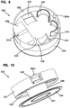
- an exemplary cable storage arrangement 500 configured as a wall outlet 500 is presented.
- the wall outlet 500 stores the patch cord or jumper cable 190 , which has connectors 192 , 194 at each end, in a coiled fashion. As configured, only the length of jumper cable 190 needed to extend from the wall outlet 500 to the ONT 180 is dispensed, with the remainder being stored within the wall outlet 500 in a concealed fashion.
- the wall outlet 500 includes a base portion 520 .
- An adapter 536 is provided at the base portion 520 and is located at least partially within the base portion 520 .
- the adapter 536 may be connected to a subscriber cable 110 that extends into an interior of the base portion 520 .
- a spool structure 537 is provided and extends from the base portion 420 with a first hub portion 540 and an oppositely disposed second hub portion 542 .
- a first cable retaining flange 550 extends from the first hub portion 540 to form a first lobe structure while a second cable retaining flange 552 extends from the second hub portion 542 to form a second lobe structure.
- the flanges 550 , 552 extend at an oblique angle from the hub portions 540 , 542 to allow for easier dispensing of the cable off of the flanges 550 , 552 .
- the spool structure 537 can be defined as including the base structure 520 , the hub portions 540 , 542 and the cable retaining flanges 550 , 552 .
- the first fiber optic connector 192 is connected to the adapter 536 and the length of cable 190 between the connectors 192 , 194 is coiled about the hub portions 540 , 542 and between the base portion 520 and the flanges 550 , 552 .
- an exemplary cable storage arrangement 600 configured as a wall outlet 600 is presented.
- the wall outlet 600 stores the patch cord or jumper cable 190 , which has connectors 192 , 194 at each end, in a coiled fashion. As configured, only the length of jumper cable 190 needed to extend from the wall outlet 600 to the ONT 180 is dispensed, with the remainder being stored within the wall outlet 600 in a concealed fashion.
- the wall outlet 600 also includes a mounting plate 602 , a base structure 620 , and a cover 660 .
- the operation of the wall outlet 600 is similar in principle to the wall outlet 200 in that the base structure 620 defines a fixed spool about which the cable 190 can be wound and unwound with the cove rotatably disposed on the base structure 620 .
- the mounting plate 602 has a sidewall 604 extending between a first side 606 and a second opposite side 608 . As shown, the sidewall 604 defines a cylindrically shaped outer profile. Other shapes are possible.
- the mounting plate 602 is also provided with a pair of apertures 610 extending between the first and second sides 606 , 608 .
- the apertures 610 allow for a fastener (not shown) to extend through the mounting plate 602 such that the mounting plate 602 can be mounted to a wall or other similar structure, with the first side 606 adjacent the wall. It is noted that the mounting plate 602 could be attached to a wall through other means, such as by an adhesive.
- the second side 608 of the mounting plate 602 is provided with a pair of attachment structures 612 configured to engage with corresponding attachment structures 624 on the base structure 620 .
- This structure allows the base structure 620 to be mounted and retained onto the mounting plate 602 after the mounting plate 602 has been secured to a wall.
- the attachment structures 612 are each configured with a recess 612 a and a latch aperture 612 b while each attachment structure 624 is configured with a tab 624 a that is received by the recess 612 a and with a latch 612 b that can provide a snap-fit type connection with the latch aperture 612 b .
- This configuration ensures a proper orientation of the base structure 620 with respect to the mounting plate 602 .
- the mounting plate 602 further includes an exit aperture, channel, or recess 614 through which a cable 191 extending from the base structure 620 can extend.
- a pair of bend radius limiters 616 can be provided to ensure that the cable 191 is properly guided through the recess 614 .
- the base structure 620 has a first sidewall 622 , extending from a base wall 638 , upon which at least a portion of the attachment structures 624 are disposed.
- the first sidewall 622 is shown as being cylindrically shaped and defines an internal cavity 623 in conjunction with the base wall 638 .
- the base structure sidewall 622 and the mounting plate sidewall 604 have a similar dimension. Accordingly, when the base structure 620 is secured to the mounting plate 602 , the sidewalls 602 , 622 are flush. In this position, the base structure sidewall 622 is received within the sidewall 604 and the second side 208 of the mounting plate 202 encloses the internal cavity 623 of the base structure 620 .
- the base structure 620 is further shown as including an adapter mounting structure 626 extending from the base wall 638 and into the internal cavity 223 .
- the base structure 620 also includes a pair of bend radius limiters 628 , 630 extending from the base wall 638 and an aperture 632 extending through the base wall 638 .
- the adapter mounting structure 226 receives and retains an adapter 636 in a snap-fit type arrangement.
- the adapter 636 is a male-to-male type adapter that receives optical connector 155 and optical connector 192 of the jumper cable 190 .
- the jumper cable 190 extends in a channel defined by the spaced apart and parallel bend radius limiters 628 , 630 and then through the aperture 632 such that the remaining length of the jumper cable 190 can be coiled about a drum region or spool structure 637 .
- the spool structure 637 is defined by the base wall 638 , a hub portion 648 , and a second wall 650 parallel to the base wall 638 .
- the bend radius limiters 628 , 630 prevent jumper cable 190 from bending too sharply before passing through aperture 632 .
- the base structure 620 additionally includes a pair of bend radius limiters 634 that act to guide cable 191 through recess 614 in cooperation with the adjacently disposed bend radius limiters 616 .
- the spool structure 637 can be covered by the cover 660 such that the portion of the jump cable 190 wound about the spool structure 637 is concealed from view.
- the cover 660 can be provided with a front wall 662 from which a cylindrical sidewall 664 extends.
- the sidewall 664 can be provided with a plurality of ribs 667 to maintain proper orientation of the cover 660 with respect to the base structure sidewall 602 .
- the sidewall 664 can be provided with a port structure 665 through which the jumper cable 190 can extend.
- the port structure 665 is configured as a nose structure extending away from the sidewall 664 and defines a central passageway 665 a between a pair of bend radius limiters 665 b and a removable bottom plate 665 c that is snap-fit to the port structure 665 via snap-fit type latches received in apertures of the port structure 665 .
- the cable 190 extends from the spool structure 637 and through the central passageway 665 a as the cable 190 is fed into or out of the wall outlet 600 .
- the bend radius limiters 665 b ensure that the cable 190 is carefully guided onto the spool structure 637 when the cable 190 is being wound about the spool structure 637 and is carefully guided off of the spool structure 637 when the cable 190 is being unwound from the spool structure 637 such that the cable 190 is prevented from being pulled against a sharp edge.
- the bottom plate 665 c is removable from the port structure 665 such that the passageway 665 a has an open face, thereby allowing the cover 660 to be removed from the base structure 620 without requiring the cable 190 to be completely unwound from the hub structure 637 or threaded back out of the passageway 665 a.
- the cover 260 is rotatably attached to the base structure 620 by a selector assembly 670 .
- the lock assembly 670 includes a latch member 672 and a selector plate 674 , wherein the latch member 672 rests on a recessed portion 662 a of the front wall 662 and extends through an aperture 663 of the front wall 662 .
- the selector plate 674 is disposed on the opposite side of the front wall 662 from the latch member 672 and has a handle portion 674 a that extends through an aperture 672 a in the latch member 672 .
- the handle portion 674 a extends from a plate portion 674 b .
- the latch member 672 is secured to the base structure 620 via latch members 672 that extend into the central area 648 a defined by the hub portion and snap-fit onto tabs 648 b extending from the sidewall of the hub portion 648 .
- the selector plate 674 is slidably disposed between the latch member 672 and a top edge 648 c of the hub portion 648 .
- Grooves 648 d are provided in the top edge 648 c that receive a guide rib 674 c on the selector plate 674 .
- the grooves 648 d and rib 674 c cooperate such that the selector plate 674 is constrained to be slidable in a single direction D 1 parallel with the direction of the guide rib 674 c .
- the cover 660 is also rotatable with respect to the latch member 672 and the base structure 620 , provided the selector plate 74 is in a neutral position.
- the selector plate 674 is configured to be moved into one of three different positions via the handle portion 674 a . These three positions are defined as discrete positions by an indexing feature 674 d on the selector plate 675 , configured as a protrusion extending from a cantilevered arm, and by an indexing feature 672 c on the latch member 672 , configured as two pairs of spaced apart protrusions. In a first position, the protrusions of the indexing feature 674 d are entirely on a first side of the protrusions of the indexing feature 672 c .
- each protrusion of the indexing feature 674 d is between two of the protrusions of the indexing feature 672 c .
- the protrusions of the indexing feature 674 d are entirely on a second side of the protrusions of the indexing feature 672 c .
- the protrusions of the indexing features 672 c , 674 d engage each other such that the cantilevered arm of the indexing feature 672 is deflected.
- the protrusions of the indexing feature 674 d snap back via the cantilevered arm as they are no longer held away by the protrusions of the indexing feature 672 c .
- the selector plate 674 can also be provided with end stops 674 e which engage with the hub portion sidewall 648 to prevent the selector plate 674 from moving beyond the first position and from moving beyond the third position.
- the selector plate 674 is also provided with three pairs of engagement members 674 f , 674 g , 674 h .
- the pairs of engagement members 674 e , 674 f , 674 g are either engaged or disengaged with projection members 668 which extend from the cover front wall 662 in a circumferential arrangement.
- Each of the first and third pair of engagement members 674 f , 674 h is configured as a ramped protrusion extending from a cantilevered arm.
- each of the second pair of engagement members 674 g is configured as a protrusion extending directly from the main body of the selector plate 674 without a ramped surface on either side of the protrusion.
- the projection members 668 are provided with a trapezoidal shape to ensure that the engagement members 674 , 674 f , 674 g are presented generally orthogonally against the side surfaces of the projection members 668 .
- the cover 660 is enabled to rotate in a first rotational direction R 1 (e.g. the direction that allows cable to be wound about the hub) but prevented from rotating in a second opposite rotational direction R 2 (e.g. the direction that allows the cable to be unwound about the hub).
- R 1 e.g. the direction that allows cable to be wound about the hub
- R 2 e.g. the direction that allows the cable to be unwound about the hub
- the engagement members 674 h engage between the projection members 668 , as most easily seen at FIG. 42 . Due to the orientation of the ramped surfaces on the protrusions of the engagement members 674 h , which is the opposite orientation of the ramped surfaces on the protrusions of the engagement members 674 h , the cover 660 is enabled to rotate in the second rotational direction R 2 but prevented from rotating in the first rotational direction R 1 . When the cover 660 is rotated in the second rotational direction R 2 , the ramped side of the protrusions of the engagement members 674 h allows the protrusions to deflect away from the projection members 668 via the cantilevered arm.
- the engagement members 674 g engage between the projection members 668 , as most easily seen at FIG. 43 .
- the engagement members 674 g are configured as protrusions without ramped surfaces and without any means to allow for deflection away from the projection members 668 , the cover 660 is prevented from moving in either of the first and second rotational directions R 1 , R 2 when the selector plate 674 is moved to the second position.
- the cable 190 can neither be fed out of our wound into the wall outlet 600 .
- the wall outlet 600 can also be provided with various indicia to allow an operator to understand what position into which the selector plate 674 has been placed and which rotational direction R 1 , R 2 relates to feeding out the cable and winding the cable back into the wall outlet 600 .
- indicia 680 a can be provided on the cover 660 , for example the port structure 665 , to indicate the winding direction of the cable that will result in the cable being wound into the wall outlet 600 .
- Indicia 680 b can also be provided on the cover 660 , for example the port structure 665 , to indicate the winding direction of the cable that will result in the cable being unwound and fed out of the wall outlet 600 .
- Indicia 680 c and 680 d can also be provided on the cover to provide an indication as to which direction to move the selector plate 674 in order to attain the desired allowed rotational direction for the cover 660 .
- Indicia 680 e and 680 f can also be provided on the selector plate 674 to indicate the position of the selector plate 674 .
- indicia 680 e can be associated with the first position of the selector plate 674 while indicia 680 f can be associated with the third position of the selector plate 674 .
- the aperture 672 a and selector plate 674 are configured such that only indicia 680 e or indicia 680 f is visible through the aperture 672 a at any single time. This configuration ensures that it is clear to an operator that the indicia associated with the present position of the selector plate 674 is viewable through the aperture 672 a.
- cable storage arrangements 200 , 300 , 400 , and 500 , 600 are described as being configure as wall outlets, their use and application is not limited to any such configuration.
- cable storage arrangements 200 , 300 , 400 , 500 , 600 can be located between a wall outlet box 112 and an ONT 180 , wherein a cable from the wall outlet box 112 or ONT 180 extends to the cable storage arrangement 200 , 300 , 400 , 500 , 600 and the jumper cable 190 extends to the other of the wall outlet box 112 and the ONT 180 .
- the cable storage arrangement 200 , 300 , 400 , 500 , 600 can be configured such that the jumper cable 190 extends to both the wall outlet box 112 and the ONT 180 , for example, by providing a free length of cable 190 at connector 192 instead of an adapter 236 , 336 , 436 , 536 , 636 .
- the wall outlet 600 is used as a cable storage component in a telecommunications package or box 700 which also includes an ONT 180 connected to a wireless (wi-fi) router 115 via a cable 114 a .
- the telecommunications box 700 includes a cover 702 attached to a base 704 that defines an interior space 706 .
- the ONT 114 , the router 115 are mounted to the base and the wall outlet 600 is mounted above the ONT 114 .
- the cable 191 from the wall outlet 600 is routed to the ONT 114 .
- the stored cable 190 in the wall outlet 600 can be dispensed and routed to a wall outlet box 112 or can be used as the subscriber cable 110 .
- FIGS. 69 to 72 which is similar to the telecommunications box 700 in that a router 115 and ONT 114 are mounted within an interior space 806 defined by a cover 802 and a base 804 .
- a different storage component 900 is utilized instead of wall outlet 600 .
- storage component 900 is provided with a central aperture 902 through which a pair of latch members 808 extend from the base 804 in order to secure the storage component 900 to the base 804 .
- the latch members 808 form a snap-fit type connection with the storage component 900 and allow for the storage component 900 to rotate with respect to the base 804 .
- the storage component 900 has a lower spool portion 904 about which cable 190 can be wound and an upper portion 906 which receives an end of the cable 190 and an adapter 908 .
- Bend radius limiter structures 910 may be provided at the upper portion 906 to guide the cable 190 through an aperture leading from the lower portion 904 to the adapter 908 .
- the upper portion 906 may be provided with a sidewall having ridges or a waved surface 912 to allow an operator to wind or unwind the cable 190 from the lower spool portion 904 by manually gripping and rotating the storage component 900 .
- the cable 190 can be unwound from the lower spool portion 904 by simply pulling the cable 190 .
- the base 804 can also be provided with an exit passageway 810 defined between a pair of bend radius limiters 812 to allow the cable 190 to be routed externally of the box 800 .
- storage components 600 and 900 are shown for the embodiments of FIGS. 48 to 54 , any of the above disclosed wall outlets may be utilized.
- F facility R residences 100 fiber optic network 102 feeder cable 104 cable input location 106 fiber optic enclosure 108 riser cable 110 subscriber cable 112 wall outlet box 114 ONT 114a ONT to Wi-Fi cable 117 optical connector 118 power cable 190 jumper cable 192 connector 194 connector 200 wall outlet 202 mounting plate 204 sidewall 206 first side 208 second side 210 apertures 212 attachment structure 212a channel 212b open end 212c closed end 220 base structure 222 first sidewall 223 internal cavity 224 attachment structure 224a rib 224b rib 226 adapter mounting structure 228 bend radius limiter 230 bend radius limiter 232 aperture 234 aperture 236 adapter 237 spool structure 238 base wall 248 hub portion 250 second wall 252 first socket 254 second socket 260 cover 262 front wall 264 sidewall 265 projection 266 port 268 latches 270 flange wall 300 outlet 302 base part 304 attachment part 306 first portion 308 second portion 310 first portion 312
Abstract
Description
| List of Reference Numerals and Corresponding Features |
| F | facility | ||
| R | residences | ||
| 100 | fiber optic network | ||
| 102 | feeder cable | ||
| 104 | cable input location | ||
| 106 | fiber optic enclosure | ||
| 108 | riser cable | ||
| 110 | subscriber cable | ||
| 112 | wall outlet box | ||
| 114 | ONT | ||
| 114a | ONT to Wi-Fi cable | ||
| 117 | optical connector | ||
| 118 | power cable | ||
| 190 | jumper cable | ||
| 192 | connector | ||
| 194 | connector | ||
| 200 | wall outlet | ||
| 202 | mounting plate | ||
| 204 | sidewall | ||
| 206 | first side | ||
| 208 | second side | ||
| 210 | apertures | ||
| 212 | attachment structure | ||
| 212a | channel | ||
| 212b | open end | ||
| 212c | closed end | ||
| 220 | base structure | ||
| 222 | first sidewall | ||
| 223 | internal cavity | ||
| 224 | attachment structure | ||
| 224a | rib | ||
| 224b | rib | ||
| 226 | adapter mounting structure | ||
| 228 | bend radius limiter | ||
| 230 | bend radius limiter | ||
| 232 | aperture | ||
| 234 | aperture | ||
| 236 | adapter | ||
| 237 | spool structure | ||
| 238 | base wall | ||
| 248 | hub portion | ||
| 250 | second wall | ||
| 252 | first socket | ||
| 254 | second socket | ||
| 260 | cover | ||
| 262 | front wall | ||
| 264 | sidewall | ||
| 265 | projection | ||
| 266 | port | ||
| 268 | latches | ||
| 270 | flange wall | ||
| 300 | outlet | ||
| 302 | base part | ||
| 304 | attachment part | ||
| 306 | first portion | ||
| 308 | second portion | ||
| 310 | first portion | ||
| 312 | second portion | ||
| 314 | cover | ||
| 316 | recess | ||
| 318 | aperture | ||
| 320 | internal cavity | ||
| 322 | hollow winding interior | ||
| 324 | bushing | ||
| 336 | adapter | ||
| 400 | outlet | ||
| 420 | base structure | ||
| 420a | front face | ||
| 436 | adapter | ||
| 437 | spool structure | ||
| 438 | base wall | ||
| 448 | hub portion | ||
| 450 | cable retaining wall | ||
| 450a | front face | ||
| 500 | outlet | ||
| 520 | base structure | ||
| 536 | adapter | ||
| 537 | spool structure | ||
| 538 | base wall | ||
| 540 | first hub portion | ||
| 542 | second hub portion | ||
| 550 | first flange portion | ||
| 552 | second flange portion | ||
| 600 | wall outlet | ||
| 602 | mounting plate | ||
| 604 | sidewall | ||
| 606 | first side | ||
| 608 | second side | ||
| 610 | apertures | ||
| 612 | attachment structure | ||
| 612a | recess | ||
| 612b | latch aperture | ||
| 614 | recess | ||
| 616 | radius limiter | ||
| 620 | base structure | ||
| 622 | sidewall | ||
| 623 | interior cavity | ||
| 624 | attachment structure | ||
| 624a | tab | ||
| 624b | latch | ||
| 626 | adapter mounting structure | ||
| 628 | bend radius limiter | ||
| 630 | bend radius limiter | ||
| 632 | aperture | ||
| 634 | bend radius limiter | ||
| 637 | spool structure | ||
| 638 | base wall | ||
| 648 | hub portion | ||
| 648a | interior portion | ||
| 648b | latch tabs | ||
| 648c | top edge | ||
| 648d | grooves | ||
| 650 | second wall | ||
| 660 | cover | ||
| 662 | front wall | ||
| 662a | recessed portion | ||
| 663 | aperture | ||
| 664 | sidewall | ||
| 665 | port structure | ||
| 665a | central passageway | ||
| 665b | bend radius limiter | ||
| 665c | bottom plate | ||
| 667 | ribs | ||
| 668 | projection members | ||
| 670 | selector assembly | ||
| 672 | latch member | ||
| 672a | aperture | ||
| 672b | latch member | ||
| 674 | selector plate | ||
| 674a | handle portion | ||
| 674b | plate portion | ||
| 674c | guide rib | ||
| 674d | indexing feature | ||
| 674e | end stops | ||
| 674f | engagement members | ||
| 674g | engagement members | ||
| 674h | engagement members | ||
| 680a | indicia | ||
| 680b | indicia | ||
| 680c | indicia | ||
| 680d | indicia | ||
| 680e | indicia | ||
| 680f | indicia | ||
| 700 | telecommunications box | ||
| 702 | cover | ||
| 704 | base | ||
| 706 | interior space | ||
| 800 | telecommunications box | ||
| 802 | cover | ||
| 804 | base | ||
| 806 | interior space | ||
| 808 | latch members | ||
| 900 | storage component | ||
| 902 | central aperture | ||
| 904 | lower spool portion | ||
| 906 | upper storage portion | ||
| 908 | adapter | ||
| 910 | bend radius limiter structures | ||
| 912 | ridged sidewall | ||
| D1 | slide direction | ||
| R1 | first rotational direction | ||
| R2 | second rotational direction | ||
Claims (14)
Priority Applications (1)
| Application Number | Priority Date | Filing Date | Title |
|---|---|---|---|
| US15/567,923 US10782499B2 (en) | 2015-04-22 | 2016-04-22 | Cable storage arrangement |
Applications Claiming Priority (3)
| Application Number | Priority Date | Filing Date | Title |
|---|---|---|---|
| US201562151239P | 2015-04-22 | 2015-04-22 | |
| PCT/EP2016/059103 WO2016170171A2 (en) | 2015-04-22 | 2016-04-22 | Cable storage arrangement |
| US15/567,923 US10782499B2 (en) | 2015-04-22 | 2016-04-22 | Cable storage arrangement |
Related Parent Applications (1)
| Application Number | Title | Priority Date | Filing Date |
|---|---|---|---|
| PCT/EP2016/059103 A-371-Of-International WO2016170171A2 (en) | 2015-04-22 | 2016-04-22 | Cable storage arrangement |
Related Child Applications (1)
| Application Number | Title | Priority Date | Filing Date |
|---|---|---|---|
| US17/027,050 Continuation US20210072484A1 (en) | 2015-04-22 | 2020-09-21 | Cable storage arrangement |
Publications (2)
| Publication Number | Publication Date |
|---|---|
| US20180299632A1 US20180299632A1 (en) | 2018-10-18 |
| US10782499B2 true US10782499B2 (en) | 2020-09-22 |
Family
ID=55808594
Family Applications (2)
| Application Number | Title | Priority Date | Filing Date |
|---|---|---|---|
| US15/567,923 Active US10782499B2 (en) | 2015-04-22 | 2016-04-22 | Cable storage arrangement |
| US17/027,050 Abandoned US20210072484A1 (en) | 2015-04-22 | 2020-09-21 | Cable storage arrangement |
Family Applications After (1)
| Application Number | Title | Priority Date | Filing Date |
|---|---|---|---|
| US17/027,050 Abandoned US20210072484A1 (en) | 2015-04-22 | 2020-09-21 | Cable storage arrangement |
Country Status (3)
| Country | Link |
|---|---|
| US (2) | US10782499B2 (en) |
| EP (2) | EP4043938A1 (en) |
| WO (1) | WO2016170171A2 (en) |
Cited By (4)
| Publication number | Priority date | Publication date | Assignee | Title |
|---|---|---|---|---|
| US20220163745A1 (en) * | 2018-01-19 | 2022-05-26 | CommScope Connectivity Belgium BVBA | Optical fiber loop relaxation |
| US11493718B2 (en) * | 2019-03-21 | 2022-11-08 | Ppc Broadband, Inc. | Multi-fiber reel and adapter assembly |
| US20230152531A1 (en) * | 2015-10-12 | 2023-05-18 | 3M Innovative Properties Company | Optical waveguide positioning feature in a multiple waveguides connector |
| US11899260B2 (en) | 2016-04-04 | 2024-02-13 | Opterna Am, Inc. | Fiber optic cable deployment assemblies, systems, and methods |
Families Citing this family (11)
| Publication number | Priority date | Publication date | Assignee | Title |
|---|---|---|---|---|
| US7756379B2 (en) * | 2007-08-06 | 2010-07-13 | Adc Telecommunications, Inc. | Fiber optic enclosure with internal cable spool |
| US10754115B2 (en) | 2015-04-22 | 2020-08-25 | CommScope Connectivity Belgium BVBA | Deploying optical fibers within a multi-dwelling unit |
| EP4043938A1 (en) | 2015-04-22 | 2022-08-17 | CommScope Connectivity Belgium BVBA | Cable storage arrangement |
| US11402596B2 (en) | 2019-10-28 | 2022-08-02 | Opterna Am, Inc. | Terminal system assemblies with breakout/adapter modules |
| CN110824624A (en) * | 2019-11-22 | 2020-02-21 | 湖南彗驰科技有限公司 | Optical fiber switching device |
| US11391898B2 (en) | 2020-06-12 | 2022-07-19 | Hewlett Packard Enterprise Development Lp | Direct opto-mechanical connection for pluggable optical transceivers |
| US11228819B1 (en) * | 2020-06-30 | 2022-01-18 | Go!Foton Holdings, Inc. | Easy access patch panel |
| WO2022015528A2 (en) * | 2020-07-13 | 2022-01-20 | Corning Research & Development Corporation | Cable slack management apparatus for co-packaged opto-electrical devices |
| US11415763B2 (en) * | 2020-08-07 | 2022-08-16 | Hewlett Packard Enterprise Development Lp | Rigid-plane optical jumper for pluggable optical transceivers |
| WO2023069304A1 (en) * | 2021-10-19 | 2023-04-27 | Corning Research & Development Corporation | Cable slack management apparatus for co-packaged opto-electrical devices |
| US20230176308A1 (en) * | 2021-12-03 | 2023-06-08 | Ppc Broadband Fiber Ltd. | Fiber reel and demarcation box assembly with reel controller and/or reversible cover |
Citations (11)
| Publication number | Priority date | Publication date | Assignee | Title |
|---|---|---|---|---|
| US6889926B1 (en) | 2002-05-30 | 2005-05-10 | Shakespeare Company | Spincast fishing reel having improved front cover and method of making same |
| JP2009131212A (en) | 2007-11-30 | 2009-06-18 | Daiwa Seiko Inc | Spinning reel for fishing use |
| EP2159618A1 (en) | 2008-08-27 | 2010-03-03 | Corning Cable Systems LLC | Optical Fiber Assemblies For Fiber to the Subscriber Applications |
| US20120055965A1 (en) * | 2009-05-13 | 2012-03-08 | Zhengping Zhang | Personal portable device keeper |
| WO2012138856A1 (en) | 2011-04-05 | 2012-10-11 | Communication Systems, Inc. | Optical fiber cable drop interface box |
| US20130094828A1 (en) | 2010-06-18 | 2013-04-18 | Adc Communications (Shanghai) Co., Ltd. | Fiber optic distribution terminal and method of deploying fiber distribution cable |
| US20140010513A1 (en) * | 2007-08-06 | 2014-01-09 | Adc Telecommunications, Inc. | Fiber optic enclosure with internal cable spool |
| US20140224913A1 (en) * | 2013-02-14 | 2014-08-14 | Haworth, Inc. | Cable retractor |
| US9354415B2 (en) * | 2011-02-01 | 2016-05-31 | Opterna Technology Limited | Fiber distribution hubs |
| WO2016100927A1 (en) | 2014-12-19 | 2016-06-23 | Commscope Technologies Llc | Coreless wound coil dispenser with optional cable storage for an optical terminal network |
| WO2016170172A1 (en) | 2015-04-22 | 2016-10-27 | CommScope Connectivity Belgium BVBA | Deploying optical fibers within a multi-dwelling unit |
Family Cites Families (8)
| Publication number | Priority date | Publication date | Assignee | Title |
|---|---|---|---|---|
| US20030083273A1 (en) * | 1999-04-20 | 2003-05-01 | Tod M. Woolf | Antisense oligomers |
| US20060072302A1 (en) * | 2004-10-01 | 2006-04-06 | Chien Tseng L | Electro-luminescent (EL) illuminated wall plate device with push-tighten frame means |
| US7369739B2 (en) * | 2005-08-08 | 2008-05-06 | Fiber Optic Protection Systems, Inc. | Fiber optic cable protective apparatus |
| US7546969B2 (en) * | 2005-11-15 | 2009-06-16 | Yoshisuke Kuramoto | Systems and methods of winding a portable cord |
| US7418181B2 (en) * | 2006-02-13 | 2008-08-26 | Adc Telecommunications, Inc. | Fiber optic splitter module |
| US8146853B2 (en) * | 2009-09-28 | 2012-04-03 | Jeanne Godett | Optical laser fiber reel |
| BR122016029886A2 (en) * | 2012-12-19 | 2019-08-27 | Tyco Electronics Raychem Bvba | distribution device with additional distributors in increments |
| EP4043938A1 (en) | 2015-04-22 | 2022-08-17 | CommScope Connectivity Belgium BVBA | Cable storage arrangement |
-
2016
- 2016-04-22 EP EP22150264.4A patent/EP4043938A1/en not_active Withdrawn
- 2016-04-22 US US15/567,923 patent/US10782499B2/en active Active
- 2016-04-22 WO PCT/EP2016/059103 patent/WO2016170171A2/en active Application Filing
- 2016-04-22 EP EP16718347.4A patent/EP3286589B1/en active Active
-
2020
- 2020-09-21 US US17/027,050 patent/US20210072484A1/en not_active Abandoned
Patent Citations (11)
| Publication number | Priority date | Publication date | Assignee | Title |
|---|---|---|---|---|
| US6889926B1 (en) | 2002-05-30 | 2005-05-10 | Shakespeare Company | Spincast fishing reel having improved front cover and method of making same |
| US20140010513A1 (en) * | 2007-08-06 | 2014-01-09 | Adc Telecommunications, Inc. | Fiber optic enclosure with internal cable spool |
| JP2009131212A (en) | 2007-11-30 | 2009-06-18 | Daiwa Seiko Inc | Spinning reel for fishing use |
| EP2159618A1 (en) | 2008-08-27 | 2010-03-03 | Corning Cable Systems LLC | Optical Fiber Assemblies For Fiber to the Subscriber Applications |
| US20120055965A1 (en) * | 2009-05-13 | 2012-03-08 | Zhengping Zhang | Personal portable device keeper |
| US20130094828A1 (en) | 2010-06-18 | 2013-04-18 | Adc Communications (Shanghai) Co., Ltd. | Fiber optic distribution terminal and method of deploying fiber distribution cable |
| US9354415B2 (en) * | 2011-02-01 | 2016-05-31 | Opterna Technology Limited | Fiber distribution hubs |
| WO2012138856A1 (en) | 2011-04-05 | 2012-10-11 | Communication Systems, Inc. | Optical fiber cable drop interface box |
| US20140224913A1 (en) * | 2013-02-14 | 2014-08-14 | Haworth, Inc. | Cable retractor |
| WO2016100927A1 (en) | 2014-12-19 | 2016-06-23 | Commscope Technologies Llc | Coreless wound coil dispenser with optional cable storage for an optical terminal network |
| WO2016170172A1 (en) | 2015-04-22 | 2016-10-27 | CommScope Connectivity Belgium BVBA | Deploying optical fibers within a multi-dwelling unit |
Non-Patent Citations (1)
| Title |
|---|
| International Search Report and Written Opinion of the International Searching Authority for corresponding International Patent Application No. PCT/EP2016/059103 dated Nov. 14, 2016, 17 pages. |
Cited By (6)
| Publication number | Priority date | Publication date | Assignee | Title |
|---|---|---|---|---|
| US20230152531A1 (en) * | 2015-10-12 | 2023-05-18 | 3M Innovative Properties Company | Optical waveguide positioning feature in a multiple waveguides connector |
| US11906789B2 (en) * | 2015-10-12 | 2024-02-20 | 3M Innovative Properties Company | Optical waveguide positioning feature in a multiple waveguides connector |
| US11899260B2 (en) | 2016-04-04 | 2024-02-13 | Opterna Am, Inc. | Fiber optic cable deployment assemblies, systems, and methods |
| US20220163745A1 (en) * | 2018-01-19 | 2022-05-26 | CommScope Connectivity Belgium BVBA | Optical fiber loop relaxation |
| US11709332B2 (en) * | 2018-01-19 | 2023-07-25 | CommScope Connectivity Belgium BVBA | Optical fiber loop relaxation |
| US11493718B2 (en) * | 2019-03-21 | 2022-11-08 | Ppc Broadband, Inc. | Multi-fiber reel and adapter assembly |
Also Published As
| Publication number | Publication date |
|---|---|
| EP3286589B1 (en) | 2022-01-12 |
| WO2016170171A2 (en) | 2016-10-27 |
| US20180299632A1 (en) | 2018-10-18 |
| US20210072484A1 (en) | 2021-03-11 |
| EP3286589A2 (en) | 2018-02-28 |
| EP4043938A1 (en) | 2022-08-17 |
| WO2016170171A3 (en) | 2016-12-15 |
Similar Documents
| Publication | Publication Date | Title |
|---|---|---|
| US10782499B2 (en) | Cable storage arrangement | |
| USRE49385E1 (en) | Fiber optic cable distribution box | |
| US11327262B2 (en) | Fiber termination enclosure with modular plate assemblies | |
| US10852488B2 (en) | Methods and systems for distributing fiber optic telecommunications services to local area | |
| US10928602B2 (en) | Fiber optic cable deployment assemblies, systems, and methods | |
| US10754115B2 (en) | Deploying optical fibers within a multi-dwelling unit | |
| US8929708B2 (en) | Fiber organizer and distribution box | |
| US9684142B2 (en) | Rapid distribution terminal | |
| US20080199139A1 (en) | Storage Device for Use in Fiber Optic Communication Systems and Method of Using the Same | |
| US20200301078A1 (en) | Multi-fiber reel and adapter assembly | |
| EP3230780B1 (en) | Fiber optic cable slack management module |
Legal Events
| Date | Code | Title | Description |
|---|---|---|---|
| FEPP | Fee payment procedure |
Free format text: ENTITY STATUS SET TO UNDISCOUNTED (ORIGINAL EVENT CODE: BIG.); ENTITY STATUS OF PATENT OWNER: LARGE ENTITY |
|
| STPP | Information on status: patent application and granting procedure in general |
Free format text: RESPONSE TO NON-FINAL OFFICE ACTION ENTERED AND FORWARDED TO EXAMINER |
|
| STPP | Information on status: patent application and granting procedure in general |
Free format text: FINAL REJECTION MAILED |
|
| STPP | Information on status: patent application and granting procedure in general |
Free format text: RESPONSE AFTER FINAL ACTION FORWARDED TO EXAMINER |
|
| STPP | Information on status: patent application and granting procedure in general |
Free format text: ADVISORY ACTION MAILED |
|
| STPP | Information on status: patent application and granting procedure in general |
Free format text: DOCKETED NEW CASE - READY FOR EXAMINATION |
|
| STPP | Information on status: patent application and granting procedure in general |
Free format text: DOCKETED NEW CASE - READY FOR EXAMINATION |
|
| AS | Assignment |
Owner name: ADC CZECH REPUBLIC, S.R.O., CZECH REPUBLIC Free format text: ASSIGNMENT OF ASSIGNORS INTEREST;ASSIGNOR:AMBROZ, JIRI;REEL/FRAME:050814/0607 Effective date: 20191022 Owner name: COMMSCOPE CONNECTIVITY BELGIUM BVBA, BELGIUM Free format text: ASSIGNMENT OF ASSIGNORS INTEREST;ASSIGNORS:VAN BAELEN, DAVID JAN IRMA;COLLART, STEPHANE;REEL/FRAME:050814/0602 Effective date: 20191023 |
|
| STPP | Information on status: patent application and granting procedure in general |
Free format text: DOCKETED NEW CASE - READY FOR EXAMINATION |
|
| STPP | Information on status: patent application and granting procedure in general |
Free format text: NON FINAL ACTION MAILED |
|
| STPP | Information on status: patent application and granting procedure in general |
Free format text: NOTICE OF ALLOWANCE MAILED -- APPLICATION RECEIVED IN OFFICE OF PUBLICATIONS |
|
| STPP | Information on status: patent application and granting procedure in general |
Free format text: PUBLICATIONS -- ISSUE FEE PAYMENT VERIFIED |
|
| STCF | Information on status: patent grant |
Free format text: PATENTED CASE |
|
| AS | Assignment |
Owner name: COMMSCOPE CZECH REPUBLIC S.R.O., CZECH REPUBLIC Free format text: CHANGE OF NAME;ASSIGNOR:ADC CZECH REPUBLIC, S.R.O.;REEL/FRAME:060283/0826 Effective date: 20191001 |