US10773584B2 - Engine mount for vehicle - Google Patents
Engine mount for vehicle Download PDFInfo
- Publication number
- US10773584B2 US10773584B2 US16/168,651 US201816168651A US10773584B2 US 10773584 B2 US10773584 B2 US 10773584B2 US 201816168651 A US201816168651 A US 201816168651A US 10773584 B2 US10773584 B2 US 10773584B2
- Authority
- US
- United States
- Prior art keywords
- fluid
- main rubber
- engine mount
- assembly
- rubber
- Prior art date
- Legal status (The legal status is an assumption and is not a legal conclusion. Google has not performed a legal analysis and makes no representation as to the accuracy of the status listed.)
- Active, expires
Links
- 239000012530 fluid Substances 0.000 claims abstract description 95
- 230000008878 coupling Effects 0.000 claims abstract description 18
- 238000010168 coupling process Methods 0.000 claims abstract description 18
- 238000005859 coupling reaction Methods 0.000 claims abstract description 18
- 238000000034 method Methods 0.000 claims description 21
- 230000008569 process Effects 0.000 claims description 19
- 239000012528 membrane Substances 0.000 claims description 11
- 238000007789 sealing Methods 0.000 claims description 6
- 239000000470 constituent Substances 0.000 description 3
- 238000012423 maintenance Methods 0.000 description 3
- 238000012986 modification Methods 0.000 description 3
- 230000004048 modification Effects 0.000 description 3
- 238000004891 communication Methods 0.000 description 2
- 239000000446 fuel Substances 0.000 description 2
- 238000003780 insertion Methods 0.000 description 2
- 230000037431 insertion Effects 0.000 description 2
- 229910000831 Steel Inorganic materials 0.000 description 1
- 230000005540 biological transmission Effects 0.000 description 1
- 230000000903 blocking effect Effects 0.000 description 1
- 238000002485 combustion reaction Methods 0.000 description 1
- 238000013461 design Methods 0.000 description 1
- 230000000694 effects Effects 0.000 description 1
- 238000009434 installation Methods 0.000 description 1
- 238000004519 manufacturing process Methods 0.000 description 1
- 239000007769 metal material Substances 0.000 description 1
- 239000003208 petroleum Substances 0.000 description 1
- 239000010959 steel Substances 0.000 description 1
Images


Classifications
-
- B—PERFORMING OPERATIONS; TRANSPORTING
- B60—VEHICLES IN GENERAL
- B60K—ARRANGEMENT OR MOUNTING OF PROPULSION UNITS OR OF TRANSMISSIONS IN VEHICLES; ARRANGEMENT OR MOUNTING OF PLURAL DIVERSE PRIME-MOVERS IN VEHICLES; AUXILIARY DRIVES FOR VEHICLES; INSTRUMENTATION OR DASHBOARDS FOR VEHICLES; ARRANGEMENTS IN CONNECTION WITH COOLING, AIR INTAKE, GAS EXHAUST OR FUEL SUPPLY OF PROPULSION UNITS IN VEHICLES
- B60K5/00—Arrangement or mounting of internal-combustion or jet-propulsion units
- B60K5/12—Arrangement of engine supports
- B60K5/1208—Resilient supports
-
- B—PERFORMING OPERATIONS; TRANSPORTING
- B60—VEHICLES IN GENERAL
- B60K—ARRANGEMENT OR MOUNTING OF PROPULSION UNITS OR OF TRANSMISSIONS IN VEHICLES; ARRANGEMENT OR MOUNTING OF PLURAL DIVERSE PRIME-MOVERS IN VEHICLES; AUXILIARY DRIVES FOR VEHICLES; INSTRUMENTATION OR DASHBOARDS FOR VEHICLES; ARRANGEMENTS IN CONNECTION WITH COOLING, AIR INTAKE, GAS EXHAUST OR FUEL SUPPLY OF PROPULSION UNITS IN VEHICLES
- B60K5/00—Arrangement or mounting of internal-combustion or jet-propulsion units
- B60K5/12—Arrangement of engine supports
- B60K5/1266—Supports comprising friction damping devices
-
- B—PERFORMING OPERATIONS; TRANSPORTING
- B60—VEHICLES IN GENERAL
- B60K—ARRANGEMENT OR MOUNTING OF PROPULSION UNITS OR OF TRANSMISSIONS IN VEHICLES; ARRANGEMENT OR MOUNTING OF PLURAL DIVERSE PRIME-MOVERS IN VEHICLES; AUXILIARY DRIVES FOR VEHICLES; INSTRUMENTATION OR DASHBOARDS FOR VEHICLES; ARRANGEMENTS IN CONNECTION WITH COOLING, AIR INTAKE, GAS EXHAUST OR FUEL SUPPLY OF PROPULSION UNITS IN VEHICLES
- B60K5/00—Arrangement or mounting of internal-combustion or jet-propulsion units
- B60K5/12—Arrangement of engine supports
- B60K5/1283—Adjustable supports, e.g. the mounting or the characteristics being adjustable
-
- F—MECHANICAL ENGINEERING; LIGHTING; HEATING; WEAPONS; BLASTING
- F16—ENGINEERING ELEMENTS AND UNITS; GENERAL MEASURES FOR PRODUCING AND MAINTAINING EFFECTIVE FUNCTIONING OF MACHINES OR INSTALLATIONS; THERMAL INSULATION IN GENERAL
- F16F—SPRINGS; SHOCK-ABSORBERS; MEANS FOR DAMPING VIBRATION
- F16F13/00—Units comprising springs of the non-fluid type as well as vibration-dampers, shock-absorbers, or fluid springs
- F16F13/04—Units comprising springs of the non-fluid type as well as vibration-dampers, shock-absorbers, or fluid springs comprising both a plastics spring and a damper, e.g. a friction damper
- F16F13/06—Units comprising springs of the non-fluid type as well as vibration-dampers, shock-absorbers, or fluid springs comprising both a plastics spring and a damper, e.g. a friction damper the damper being a fluid damper, e.g. the plastics spring not forming a part of the wall of the fluid chamber of the damper
- F16F13/08—Units comprising springs of the non-fluid type as well as vibration-dampers, shock-absorbers, or fluid springs comprising both a plastics spring and a damper, e.g. a friction damper the damper being a fluid damper, e.g. the plastics spring not forming a part of the wall of the fluid chamber of the damper the plastics spring forming at least a part of the wall of the fluid chamber of the damper
- F16F13/10—Units comprising springs of the non-fluid type as well as vibration-dampers, shock-absorbers, or fluid springs comprising both a plastics spring and a damper, e.g. a friction damper the damper being a fluid damper, e.g. the plastics spring not forming a part of the wall of the fluid chamber of the damper the plastics spring forming at least a part of the wall of the fluid chamber of the damper the wall being at least in part formed by a flexible membrane or the like
- F16F13/103—Units comprising springs of the non-fluid type as well as vibration-dampers, shock-absorbers, or fluid springs comprising both a plastics spring and a damper, e.g. a friction damper the damper being a fluid damper, e.g. the plastics spring not forming a part of the wall of the fluid chamber of the damper the plastics spring forming at least a part of the wall of the fluid chamber of the damper the wall being at least in part formed by a flexible membrane or the like characterised by method of assembly, production or treatment
-
- F—MECHANICAL ENGINEERING; LIGHTING; HEATING; WEAPONS; BLASTING
- F16—ENGINEERING ELEMENTS AND UNITS; GENERAL MEASURES FOR PRODUCING AND MAINTAINING EFFECTIVE FUNCTIONING OF MACHINES OR INSTALLATIONS; THERMAL INSULATION IN GENERAL
- F16F—SPRINGS; SHOCK-ABSORBERS; MEANS FOR DAMPING VIBRATION
- F16F13/00—Units comprising springs of the non-fluid type as well as vibration-dampers, shock-absorbers, or fluid springs
- F16F13/04—Units comprising springs of the non-fluid type as well as vibration-dampers, shock-absorbers, or fluid springs comprising both a plastics spring and a damper, e.g. a friction damper
- F16F13/06—Units comprising springs of the non-fluid type as well as vibration-dampers, shock-absorbers, or fluid springs comprising both a plastics spring and a damper, e.g. a friction damper the damper being a fluid damper, e.g. the plastics spring not forming a part of the wall of the fluid chamber of the damper
- F16F13/08—Units comprising springs of the non-fluid type as well as vibration-dampers, shock-absorbers, or fluid springs comprising both a plastics spring and a damper, e.g. a friction damper the damper being a fluid damper, e.g. the plastics spring not forming a part of the wall of the fluid chamber of the damper the plastics spring forming at least a part of the wall of the fluid chamber of the damper
- F16F13/10—Units comprising springs of the non-fluid type as well as vibration-dampers, shock-absorbers, or fluid springs comprising both a plastics spring and a damper, e.g. a friction damper the damper being a fluid damper, e.g. the plastics spring not forming a part of the wall of the fluid chamber of the damper the plastics spring forming at least a part of the wall of the fluid chamber of the damper the wall being at least in part formed by a flexible membrane or the like
- F16F13/108—Units comprising springs of the non-fluid type as well as vibration-dampers, shock-absorbers, or fluid springs comprising both a plastics spring and a damper, e.g. a friction damper the damper being a fluid damper, e.g. the plastics spring not forming a part of the wall of the fluid chamber of the damper the plastics spring forming at least a part of the wall of the fluid chamber of the damper the wall being at least in part formed by a flexible membrane or the like characterised by features of plastics springs, e.g. attachment arrangements
-
- F—MECHANICAL ENGINEERING; LIGHTING; HEATING; WEAPONS; BLASTING
- F16—ENGINEERING ELEMENTS AND UNITS; GENERAL MEASURES FOR PRODUCING AND MAINTAINING EFFECTIVE FUNCTIONING OF MACHINES OR INSTALLATIONS; THERMAL INSULATION IN GENERAL
- F16F—SPRINGS; SHOCK-ABSORBERS; MEANS FOR DAMPING VIBRATION
- F16F13/00—Units comprising springs of the non-fluid type as well as vibration-dampers, shock-absorbers, or fluid springs
- F16F13/04—Units comprising springs of the non-fluid type as well as vibration-dampers, shock-absorbers, or fluid springs comprising both a plastics spring and a damper, e.g. a friction damper
- F16F13/06—Units comprising springs of the non-fluid type as well as vibration-dampers, shock-absorbers, or fluid springs comprising both a plastics spring and a damper, e.g. a friction damper the damper being a fluid damper, e.g. the plastics spring not forming a part of the wall of the fluid chamber of the damper
- F16F13/08—Units comprising springs of the non-fluid type as well as vibration-dampers, shock-absorbers, or fluid springs comprising both a plastics spring and a damper, e.g. a friction damper the damper being a fluid damper, e.g. the plastics spring not forming a part of the wall of the fluid chamber of the damper the plastics spring forming at least a part of the wall of the fluid chamber of the damper
- F16F13/14—Units of the bushing type, i.e. loaded predominantly radially
- F16F13/1427—Units of the bushing type, i.e. loaded predominantly radially characterised by features of flexible walls of equilibration chambers; decoupling or self-tuning means
-
- F—MECHANICAL ENGINEERING; LIGHTING; HEATING; WEAPONS; BLASTING
- F16—ENGINEERING ELEMENTS AND UNITS; GENERAL MEASURES FOR PRODUCING AND MAINTAINING EFFECTIVE FUNCTIONING OF MACHINES OR INSTALLATIONS; THERMAL INSULATION IN GENERAL
- F16F—SPRINGS; SHOCK-ABSORBERS; MEANS FOR DAMPING VIBRATION
- F16F13/00—Units comprising springs of the non-fluid type as well as vibration-dampers, shock-absorbers, or fluid springs
- F16F13/04—Units comprising springs of the non-fluid type as well as vibration-dampers, shock-absorbers, or fluid springs comprising both a plastics spring and a damper, e.g. a friction damper
- F16F13/06—Units comprising springs of the non-fluid type as well as vibration-dampers, shock-absorbers, or fluid springs comprising both a plastics spring and a damper, e.g. a friction damper the damper being a fluid damper, e.g. the plastics spring not forming a part of the wall of the fluid chamber of the damper
- F16F13/08—Units comprising springs of the non-fluid type as well as vibration-dampers, shock-absorbers, or fluid springs comprising both a plastics spring and a damper, e.g. a friction damper the damper being a fluid damper, e.g. the plastics spring not forming a part of the wall of the fluid chamber of the damper the plastics spring forming at least a part of the wall of the fluid chamber of the damper
- F16F13/14—Units of the bushing type, i.e. loaded predominantly radially
- F16F13/1463—Units of the bushing type, i.e. loaded predominantly radially characterised by features of passages between working chambers
-
- F—MECHANICAL ENGINEERING; LIGHTING; HEATING; WEAPONS; BLASTING
- F16—ENGINEERING ELEMENTS AND UNITS; GENERAL MEASURES FOR PRODUCING AND MAINTAINING EFFECTIVE FUNCTIONING OF MACHINES OR INSTALLATIONS; THERMAL INSULATION IN GENERAL
- F16F—SPRINGS; SHOCK-ABSORBERS; MEANS FOR DAMPING VIBRATION
- F16F13/00—Units comprising springs of the non-fluid type as well as vibration-dampers, shock-absorbers, or fluid springs
- F16F13/04—Units comprising springs of the non-fluid type as well as vibration-dampers, shock-absorbers, or fluid springs comprising both a plastics spring and a damper, e.g. a friction damper
- F16F13/06—Units comprising springs of the non-fluid type as well as vibration-dampers, shock-absorbers, or fluid springs comprising both a plastics spring and a damper, e.g. a friction damper the damper being a fluid damper, e.g. the plastics spring not forming a part of the wall of the fluid chamber of the damper
- F16F13/08—Units comprising springs of the non-fluid type as well as vibration-dampers, shock-absorbers, or fluid springs comprising both a plastics spring and a damper, e.g. a friction damper the damper being a fluid damper, e.g. the plastics spring not forming a part of the wall of the fluid chamber of the damper the plastics spring forming at least a part of the wall of the fluid chamber of the damper
- F16F13/14—Units of the bushing type, i.e. loaded predominantly radially
- F16F13/1481—Units of the bushing type, i.e. loaded predominantly radially characterised by features of plastic springs, e.g. presence of cavities or stiffeners; characterised by features of flexible walls of equilibration chambers, i.e. membranes
-
- F—MECHANICAL ENGINEERING; LIGHTING; HEATING; WEAPONS; BLASTING
- F16—ENGINEERING ELEMENTS AND UNITS; GENERAL MEASURES FOR PRODUCING AND MAINTAINING EFFECTIVE FUNCTIONING OF MACHINES OR INSTALLATIONS; THERMAL INSULATION IN GENERAL
- F16F—SPRINGS; SHOCK-ABSORBERS; MEANS FOR DAMPING VIBRATION
- F16F13/00—Units comprising springs of the non-fluid type as well as vibration-dampers, shock-absorbers, or fluid springs
- F16F13/04—Units comprising springs of the non-fluid type as well as vibration-dampers, shock-absorbers, or fluid springs comprising both a plastics spring and a damper, e.g. a friction damper
- F16F13/06—Units comprising springs of the non-fluid type as well as vibration-dampers, shock-absorbers, or fluid springs comprising both a plastics spring and a damper, e.g. a friction damper the damper being a fluid damper, e.g. the plastics spring not forming a part of the wall of the fluid chamber of the damper
- F16F13/08—Units comprising springs of the non-fluid type as well as vibration-dampers, shock-absorbers, or fluid springs comprising both a plastics spring and a damper, e.g. a friction damper the damper being a fluid damper, e.g. the plastics spring not forming a part of the wall of the fluid chamber of the damper the plastics spring forming at least a part of the wall of the fluid chamber of the damper
- F16F13/18—Units comprising springs of the non-fluid type as well as vibration-dampers, shock-absorbers, or fluid springs comprising both a plastics spring and a damper, e.g. a friction damper the damper being a fluid damper, e.g. the plastics spring not forming a part of the wall of the fluid chamber of the damper the plastics spring forming at least a part of the wall of the fluid chamber of the damper characterised by the location or the shape of the equilibration chamber, e.g. the equilibration chamber, surrounding the plastics spring or being annular
-
- F—MECHANICAL ENGINEERING; LIGHTING; HEATING; WEAPONS; BLASTING
- F16—ENGINEERING ELEMENTS AND UNITS; GENERAL MEASURES FOR PRODUCING AND MAINTAINING EFFECTIVE FUNCTIONING OF MACHINES OR INSTALLATIONS; THERMAL INSULATION IN GENERAL
- F16F—SPRINGS; SHOCK-ABSORBERS; MEANS FOR DAMPING VIBRATION
- F16F15/00—Suppression of vibrations in systems; Means or arrangements for avoiding or reducing out-of-balance forces, e.g. due to motion
- F16F15/02—Suppression of vibrations of non-rotating, e.g. reciprocating systems; Suppression of vibrations of rotating systems by use of members not moving with the rotating systems
- F16F15/023—Suppression of vibrations of non-rotating, e.g. reciprocating systems; Suppression of vibrations of rotating systems by use of members not moving with the rotating systems using fluid means
-
- F—MECHANICAL ENGINEERING; LIGHTING; HEATING; WEAPONS; BLASTING
- F16—ENGINEERING ELEMENTS AND UNITS; GENERAL MEASURES FOR PRODUCING AND MAINTAINING EFFECTIVE FUNCTIONING OF MACHINES OR INSTALLATIONS; THERMAL INSULATION IN GENERAL
- F16F—SPRINGS; SHOCK-ABSORBERS; MEANS FOR DAMPING VIBRATION
- F16F15/00—Suppression of vibrations in systems; Means or arrangements for avoiding or reducing out-of-balance forces, e.g. due to motion
- F16F15/02—Suppression of vibrations of non-rotating, e.g. reciprocating systems; Suppression of vibrations of rotating systems by use of members not moving with the rotating systems
- F16F15/04—Suppression of vibrations of non-rotating, e.g. reciprocating systems; Suppression of vibrations of rotating systems by use of members not moving with the rotating systems using elastic means
- F16F15/08—Suppression of vibrations of non-rotating, e.g. reciprocating systems; Suppression of vibrations of rotating systems by use of members not moving with the rotating systems using elastic means with rubber springs ; with springs made of rubber and metal
-
- B—PERFORMING OPERATIONS; TRANSPORTING
- B60—VEHICLES IN GENERAL
- B60Y—INDEXING SCHEME RELATING TO ASPECTS CROSS-CUTTING VEHICLE TECHNOLOGY
- B60Y2304/00—Optimising design; Manufacturing; Testing
- B60Y2304/07—Facilitating assembling or mounting
Definitions
- the present invention relates to an engine mount for a vehicle. More particularly, it relates to an inverse-type engine mount for a vehicle in which a fluid-filled assembly and a rubber assembly are separably coupled to each other and in which a support bracket, which is to be connected to an engine, is directly and integrally assembled with the fluid-filled assembly.
- an engine mount for controlling vibration is provided at the position at which the engine is disposed and supported.
- an engine mount is mounted to a side member of a vehicle body, and a support bracket is located between the top surface of the engine mount and the engine to connect the engine mount to the engine.
- the support bracket which interconnects the engine mount and the engine, is in a form of a cantilever, and thus suffers from poor dynamic stiffness.
- the mass damper is provided at the support bracket.
- an inverse-type engine mount is utilized.
- the inverse-type engine mount is configured such that a fluid-filled assembly is located at the upper side and a rubber assembly is located at the lower side by turning over the above-described engine mount.
- an engine mount for a vehicle including a support bracket including a mounting hole formed in one end portion thereof, an engine-mounting plate provided at the opposite end portion thereof to be connected to an engine, and a coupling portion protruding from the external surface of the one end portion thereof, a fluid-filled assembly including a hook cup configured to be inserted into the mounting hole in the support bracket, and a rubber assembly configured to be mounted to a vehicle body, wherein, in the state in which the fluid-filled assembly is inserted into the mounting hole in the support bracket, the fluid-filled assembly is stacked on the top surface of the rubber assembly, and a housing of the rubber assembly is coupled to the coupling portion of the support bracket.
- the rubber assembly may include a housing having an open top portion, the housing being connected to the vehicle body, a first core including a core bolt, and a first main rubber formed at the bottom surface of the housing through a curing process to surround the first core.
- the housing may include a coupling rod integrally formed at the external circumferential surface thereof to be coupled with the coupling portion of the support bracket using a bolt.
- the fluid-filled assembly may further include an auxiliary core provided inside the second main rubber, the auxiliary core including a center-aligning protrusion formed at the center of the bottom surface thereof to be inserted into a center-aligning recess formed in the first main rubber.
- FIG. 1 is a front view illustrating an engine mount of the related art
- FIG. 2A , FIG. 2B , FIG. 2C , FIG. 2D , FIG. 2E , and FIG. 2F are perspective views illustrating a fluid-filled assembly of an engine mount for a vehicle according to an exemplary embodiment of the present invention and an assembly process thereof;
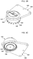
- FIG. 3A , FIG. 3B , FIG. 3C , and FIG. 3D are perspective views illustrating a process of mounting a support bracket to the fluid-filled assembly in the engine mount for a vehicle according to an exemplary embodiment of the present invention
- FIG. 4A and FIG. 4B are cross-sectional views of essential parts illustrating the process of mounting the support bracket to the fluid-filled assembly in the engine mount for a vehicle according to an exemplary embodiment of the present invention
- FIG. 7A and FIG. 7B are cross-sectional views illustrating the process of assembling the fluid-filled assembly and the support bracket with the rubber assembly in the engine mount for a vehicle according to an exemplary embodiment of the present invention
- FIG. 8 and FIG. 9 are cross-sectional views illustrating the assembly and operation of the engine mount for a vehicle according to an exemplary embodiment of the present invention.
- the fluid-filled assembly 120 includes a hook cup 121 , which is stacked on a housing 112 of a rubber assembly 110 to communicate therewith.
- the orifice member 126 has therein a hole for communication between the fluid flow passage 126 - 1 and the upper fluid chamber 120 - 1
- the orifice cover 126 - 2 has therein a hole for communication between the fluid flow passage 126 - 1 and the lower fluid chamber 120 - 2 .
- the circumference of the top surface of the second main rubber 128 comes into contact with and is supported by the circumference of the bottom surface of the orifice cover 126 - 2 .
- the external circumferential surface of the second main rubber 128 maintains sealing contact with the internal circumferential surface of the hook cup 121 with respect to the downward flow of the fluid.
- a second core 129 may be provided inside the second main rubber 128 along the circumference of the second main rubber 128 .
- the lower end portion of the second core 129 may be exposed downwards through the bottom surface of the second main rubber 128 .
- FIG. 3A , FIG. 3B , FIG. 3C , and FIG. 3D and FIG. 4A and FIG. 4B are perspective views and cross-sectional views of essential parts illustrating the process of mounting the support bracket to the fluid-filled assembly in the engine mount for a vehicle according to an exemplary embodiment of the present invention.
- FIG. 5 is a cross-sectional view illustrating the support bracket of the engine mount for a vehicle according to an exemplary embodiment of the present invention.
- the first core 114 is located inside the first main rubber 115 , and functions as a frame for supporting the first main rubber 115 .
- the core bolt 113 is disposed integrally inside the first core 114 during the process of manufacturing the first core 114 .
- the fluid-filled assembly 120 and the support bracket 100 are assembled with the rubber assembly 110 configured in the present manner.
- the fluid-filled assembly 120 is inserted into the mounting hole 101 in the support bracket 100 , and is then stacked on the top surface of the rubber assembly 110 .
- each of the coupling rods 118 formed at the housing 112 of the rubber assembly 110 is aligned with and inserted into a respective one of the coupling portions 103 of the support bracket 100 .
- the coupling rods 118 and the coupling portions 103 are securely coupled to each other by fastening the bolts 132 to the coupling rods 118 , with the result that the fluid-filled assembly 120 and the support bracket 100 are completely assembled with the rubber assembly 110 .
- the second main rubber 128 needs to come into close contact with the top surface of the first main rubber 115 while accurately maintaining the position thereof so that force may be transmitted from the first main rubber 115 to the second main rubber 128 .
- the BSR noises generated by the membrane 127 are primarily and directly isolated by the second main rubber 128 . Furthermore, the BSR noises are secondarily and indirectly isolated by the first main rubber 115 when passing through the first core 114 . In the present manner, the BSR noises generated by the membrane may be easily isolated and removed.
- the fluid-filled assembly may be easily separated from the rubber assembly, it is easy to tune the engine mount or to perform maintenance thereof. Furthermore, it is possible to tune the engine mount by replacing only a failed portion without needing replace the entire engine mount. Therefore, the costs required for tuning the engine mount or for maintenance may be reduced.
- the present invention is effective for controlling engine vibration.
Abstract
Description
Claims (11)
Applications Claiming Priority (2)
| Application Number | Priority Date | Filing Date | Title |
|---|---|---|---|
| KR1020180075179A KR102598526B1 (en) | 2018-06-29 | 2018-06-29 | Engine mount for vehicle |
| KR10-2018-0075179 | 2018-06-29 |
Publications (2)
| Publication Number | Publication Date |
|---|---|
| US20200001695A1 US20200001695A1 (en) | 2020-01-02 |
| US10773584B2 true US10773584B2 (en) | 2020-09-15 |
Family
ID=68885825
Family Applications (1)
| Application Number | Title | Priority Date | Filing Date |
|---|---|---|---|
| US16/168,651 Active 2039-01-05 US10773584B2 (en) | 2018-06-29 | 2018-10-23 | Engine mount for vehicle |
Country Status (3)
| Country | Link |
|---|---|
| US (1) | US10773584B2 (en) |
| KR (1) | KR102598526B1 (en) |
| DE (1) | DE102018126274A1 (en) |
Cited By (3)
| Publication number | Priority date | Publication date | Assignee | Title |
|---|---|---|---|---|
| US10994595B2 (en) * | 2015-12-18 | 2021-05-04 | Vibracoustic Gmbh | Engine mount pendulum support device |
| US11230178B2 (en) * | 2020-04-08 | 2022-01-25 | Hyundai Motor Company | Engine mount |
| US11358460B2 (en) * | 2020-03-31 | 2022-06-14 | Hyundai Motor Company | Engine mount for vehicle |
Families Citing this family (4)
| Publication number | Priority date | Publication date | Assignee | Title |
|---|---|---|---|---|
| USD886689S1 (en) * | 2018-10-15 | 2020-06-09 | Empi Inc. | Upper dogbone insert |
| KR20210122422A (en) * | 2020-04-01 | 2021-10-12 | 현대자동차주식회사 | Engine mount for vehicle |
| CN111688468A (en) * | 2020-07-17 | 2020-09-22 | 中国汽车工程研究院股份有限公司 | Suspension device convenient to adjust |
| CN111823844A (en) * | 2020-07-24 | 2020-10-27 | 无锡职业技术学院 | Power assembly suspension with three-dimensional rigidity variable and height and limiting interval adjustable |
Citations (7)
| Publication number | Priority date | Publication date | Assignee | Title |
|---|---|---|---|---|
| US6131893A (en) * | 1997-08-01 | 2000-10-17 | Hutchinson | Hydraulic antivibration support closed by a crimped insert |
| JP4113889B2 (en) * | 2004-08-16 | 2008-07-09 | カール・フロイデンベルク・カーゲー | Hydraulic damping bearing |
| US20080262672A1 (en) * | 2007-04-17 | 2008-10-23 | Kurashiki Kako Co., Ltd. | Abnormal noise inspection method for anti-vibration device for vehicle use |
| US20140246558A1 (en) * | 2012-02-14 | 2014-09-04 | Tokai Rubber Industries, Ltd. | Vibration damping device |
| US20150252866A1 (en) * | 2013-09-10 | 2015-09-10 | Sumitomo Riko Company Limited | Fluid-filled vibration damping device |
| US20170335920A1 (en) * | 2016-05-20 | 2017-11-23 | Sumitomo Riko Company Limited | Fluid-filled vibration damping device |
| US20190160933A1 (en) * | 2017-11-24 | 2019-05-30 | Hyundai Motor Company | Engine mount for vehicle |
Family Cites Families (1)
| Publication number | Priority date | Publication date | Assignee | Title |
|---|---|---|---|---|
| JP4953893B2 (en) * | 2007-04-17 | 2012-06-13 | 倉敷化工株式会社 | Abnormal sound inspection method for in-vehicle vibration isolator |
-
2018
- 2018-06-29 KR KR1020180075179A patent/KR102598526B1/en active IP Right Grant
- 2018-10-23 US US16/168,651 patent/US10773584B2/en active Active
- 2018-10-23 DE DE102018126274.4A patent/DE102018126274A1/en active Pending
Patent Citations (7)
| Publication number | Priority date | Publication date | Assignee | Title |
|---|---|---|---|---|
| US6131893A (en) * | 1997-08-01 | 2000-10-17 | Hutchinson | Hydraulic antivibration support closed by a crimped insert |
| JP4113889B2 (en) * | 2004-08-16 | 2008-07-09 | カール・フロイデンベルク・カーゲー | Hydraulic damping bearing |
| US20080262672A1 (en) * | 2007-04-17 | 2008-10-23 | Kurashiki Kako Co., Ltd. | Abnormal noise inspection method for anti-vibration device for vehicle use |
| US20140246558A1 (en) * | 2012-02-14 | 2014-09-04 | Tokai Rubber Industries, Ltd. | Vibration damping device |
| US20150252866A1 (en) * | 2013-09-10 | 2015-09-10 | Sumitomo Riko Company Limited | Fluid-filled vibration damping device |
| US20170335920A1 (en) * | 2016-05-20 | 2017-11-23 | Sumitomo Riko Company Limited | Fluid-filled vibration damping device |
| US20190160933A1 (en) * | 2017-11-24 | 2019-05-30 | Hyundai Motor Company | Engine mount for vehicle |
Cited By (3)
| Publication number | Priority date | Publication date | Assignee | Title |
|---|---|---|---|---|
| US10994595B2 (en) * | 2015-12-18 | 2021-05-04 | Vibracoustic Gmbh | Engine mount pendulum support device |
| US11358460B2 (en) * | 2020-03-31 | 2022-06-14 | Hyundai Motor Company | Engine mount for vehicle |
| US11230178B2 (en) * | 2020-04-08 | 2022-01-25 | Hyundai Motor Company | Engine mount |
Also Published As
| Publication number | Publication date |
|---|---|
| KR20200002086A (en) | 2020-01-08 |
| DE102018126274A1 (en) | 2020-01-02 |
| US20200001695A1 (en) | 2020-01-02 |
| KR102598526B1 (en) | 2023-11-03 |
Similar Documents
| Publication | Publication Date | Title |
|---|---|---|
| US10773584B2 (en) | Engine mount for vehicle | |
| US10549622B2 (en) | Engine mount and method of manufacturing the same | |
| CN109253206B (en) | Hydraulic engine mount | |
| KR101585403B1 (en) | Axially damped hydraulic mount assembly | |
| US20130292888A1 (en) | Air damping mount | |
| US8998186B2 (en) | Hydraulic mount for vehicle | |
| US20170267090A1 (en) | Structure for fastening engine mount | |
| US10899216B2 (en) | Active engine mount for vehicle | |
| US9382961B2 (en) | Vibration damping device | |
| JP6595371B2 (en) | Vibration isolator | |
| US10611227B2 (en) | Mount assembly for vehicle | |
| US20130175745A1 (en) | Vibration damping device | |
| CN106838113B (en) | Liquid-sealed vibration-proof device | |
| EP1245858A2 (en) | Liquid-sealed anti-vibration device | |
| US11707958B2 (en) | Insulator for vehicle suspension and manufacturing method thereof | |
| US11098785B2 (en) | Mount for vehicle | |
| US10507715B1 (en) | Mount assembly for vehicle | |
| CN212148396U (en) | Power assembly suspension system | |
| US11585425B2 (en) | Transmission mount for vehicle | |
| JP4187137B2 (en) | Liquid-filled vibration isolator | |
| JP2018062978A (en) | Antivibration device | |
| US11255396B2 (en) | Fluid-sealed engine mount | |
| JP2000065125A (en) | Vibration isolating apparatus | |
| JP3967831B2 (en) | Vibration isolator | |
| US20230272838A1 (en) | Vibration damping device |
Legal Events
| Date | Code | Title | Description |
|---|---|---|---|
| AS | Assignment |
Owner name: KIA MOTORS CORPORATION, KOREA, REPUBLIC OF Free format text: ASSIGNMENT OF ASSIGNORS INTEREST;ASSIGNOR:KIM, SEUNG WON;REEL/FRAME:047284/0939 Effective date: 20181018 Owner name: HYUNDAI MOTOR COMPANY, KOREA, REPUBLIC OF Free format text: ASSIGNMENT OF ASSIGNORS INTEREST;ASSIGNOR:KIM, SEUNG WON;REEL/FRAME:047284/0939 Effective date: 20181018 |
|
| FEPP | Fee payment procedure |
Free format text: ENTITY STATUS SET TO UNDISCOUNTED (ORIGINAL EVENT CODE: BIG.); ENTITY STATUS OF PATENT OWNER: LARGE ENTITY |
|
| STPP | Information on status: patent application and granting procedure in general |
Free format text: DOCKETED NEW CASE - READY FOR EXAMINATION |
|
| STPP | Information on status: patent application and granting procedure in general |
Free format text: NOTICE OF ALLOWANCE MAILED -- APPLICATION RECEIVED IN OFFICE OF PUBLICATIONS |
|
| STPP | Information on status: patent application and granting procedure in general |
Free format text: PUBLICATIONS -- ISSUE FEE PAYMENT VERIFIED |
|
| STCF | Information on status: patent grant |
Free format text: PATENTED CASE |
|
| MAFP | Maintenance fee payment |
Free format text: PAYMENT OF MAINTENANCE FEE, 4TH YEAR, LARGE ENTITY (ORIGINAL EVENT CODE: M1551); ENTITY STATUS OF PATENT OWNER: LARGE ENTITY Year of fee payment: 4 |