US10773445B2 - Mold, blow molding apparatus, and blow molding method - Google Patents
Mold, blow molding apparatus, and blow molding method Download PDFInfo
- Publication number
- US10773445B2 US10773445B2 US15/771,789 US201615771789A US10773445B2 US 10773445 B2 US10773445 B2 US 10773445B2 US 201615771789 A US201615771789 A US 201615771789A US 10773445 B2 US10773445 B2 US 10773445B2
- Authority
- US
- United States
- Prior art keywords
- mold
- blow molding
- grip
- preform
- cavity
- Prior art date
- Legal status (The legal status is an assumption and is not a legal conclusion. Google has not performed a legal analysis and makes no representation as to the accuracy of the status listed.)
- Active, expires
Links
- 238000000071 blow moulding Methods 0.000 title claims abstract description 82
- 238000003825 pressing Methods 0.000 claims abstract description 13
- 239000011347 resin Substances 0.000 claims description 46
- 229920005989 resin Polymers 0.000 claims description 46
- 238000004519 manufacturing process Methods 0.000 claims description 13
- 238000007664 blowing Methods 0.000 claims description 6
- 238000002347 injection Methods 0.000 description 9
- 239000007924 injection Substances 0.000 description 9
- 230000002093 peripheral effect Effects 0.000 description 9
- 238000001746 injection moulding Methods 0.000 description 8
- 230000008878 coupling Effects 0.000 description 6
- 238000010168 coupling process Methods 0.000 description 6
- 238000005859 coupling reaction Methods 0.000 description 6
- 239000000463 material Substances 0.000 description 6
- 230000007547 defect Effects 0.000 description 3
- 230000001788 irregular Effects 0.000 description 3
- 239000004278 EU approved seasoning Substances 0.000 description 2
- 230000001476 alcoholic effect Effects 0.000 description 2
- 235000013361 beverage Nutrition 0.000 description 2
- 235000011194 food seasoning agent Nutrition 0.000 description 2
- 238000010438 heat treatment Methods 0.000 description 2
- 238000012423 maintenance Methods 0.000 description 2
- 238000010586 diagram Methods 0.000 description 1
- 230000000694 effects Effects 0.000 description 1
- 238000000034 method Methods 0.000 description 1
- 238000012986 modification Methods 0.000 description 1
- 230000004048 modification Effects 0.000 description 1
- 238000000465 moulding Methods 0.000 description 1
- -1 polyethylene terephthalate Polymers 0.000 description 1
- 229920000139 polyethylene terephthalate Polymers 0.000 description 1
- 239000005020 polyethylene terephthalate Substances 0.000 description 1
Images


Classifications
-
- B—PERFORMING OPERATIONS; TRANSPORTING
- B29—WORKING OF PLASTICS; WORKING OF SUBSTANCES IN A PLASTIC STATE IN GENERAL
- B29C—SHAPING OR JOINING OF PLASTICS; SHAPING OF MATERIAL IN A PLASTIC STATE, NOT OTHERWISE PROVIDED FOR; AFTER-TREATMENT OF THE SHAPED PRODUCTS, e.g. REPAIRING
- B29C49/00—Blow-moulding, i.e. blowing a preform or parison to a desired shape within a mould; Apparatus therefor
- B29C49/28—Blow-moulding apparatus
- B29C49/30—Blow-moulding apparatus having movable moulds or mould parts
-
- B—PERFORMING OPERATIONS; TRANSPORTING
- B29—WORKING OF PLASTICS; WORKING OF SUBSTANCES IN A PLASTIC STATE IN GENERAL
- B29C—SHAPING OR JOINING OF PLASTICS; SHAPING OF MATERIAL IN A PLASTIC STATE, NOT OTHERWISE PROVIDED FOR; AFTER-TREATMENT OF THE SHAPED PRODUCTS, e.g. REPAIRING
- B29C49/00—Blow-moulding, i.e. blowing a preform or parison to a desired shape within a mould; Apparatus therefor
- B29C49/42—Component parts, details or accessories; Auxiliary operations
- B29C49/48—Moulds
-
- B—PERFORMING OPERATIONS; TRANSPORTING
- B29—WORKING OF PLASTICS; WORKING OF SUBSTANCES IN A PLASTIC STATE IN GENERAL
- B29C—SHAPING OR JOINING OF PLASTICS; SHAPING OF MATERIAL IN A PLASTIC STATE, NOT OTHERWISE PROVIDED FOR; AFTER-TREATMENT OF THE SHAPED PRODUCTS, e.g. REPAIRING
- B29C49/00—Blow-moulding, i.e. blowing a preform or parison to a desired shape within a mould; Apparatus therefor
- B29C49/0005—Blow-moulding, i.e. blowing a preform or parison to a desired shape within a mould; Apparatus therefor characterised by the material
-
- B—PERFORMING OPERATIONS; TRANSPORTING
- B29—WORKING OF PLASTICS; WORKING OF SUBSTANCES IN A PLASTIC STATE IN GENERAL
- B29C—SHAPING OR JOINING OF PLASTICS; SHAPING OF MATERIAL IN A PLASTIC STATE, NOT OTHERWISE PROVIDED FOR; AFTER-TREATMENT OF THE SHAPED PRODUCTS, e.g. REPAIRING
- B29C49/00—Blow-moulding, i.e. blowing a preform or parison to a desired shape within a mould; Apparatus therefor
- B29C49/02—Combined blow-moulding and manufacture of the preform or the parison
- B29C2049/023—Combined blow-moulding and manufacture of the preform or the parison using inherent heat of the preform, i.e. 1 step blow moulding
-
- B—PERFORMING OPERATIONS; TRANSPORTING
- B29—WORKING OF PLASTICS; WORKING OF SUBSTANCES IN A PLASTIC STATE IN GENERAL
- B29C—SHAPING OR JOINING OF PLASTICS; SHAPING OF MATERIAL IN A PLASTIC STATE, NOT OTHERWISE PROVIDED FOR; AFTER-TREATMENT OF THE SHAPED PRODUCTS, e.g. REPAIRING
- B29C49/00—Blow-moulding, i.e. blowing a preform or parison to a desired shape within a mould; Apparatus therefor
- B29C49/42—Component parts, details or accessories; Auxiliary operations
- B29C49/48—Moulds
- B29C49/4802—Moulds with means for locally compressing part(s) of the parison in the main blowing cavity
- B29C2049/4807—Moulds with means for locally compressing part(s) of the parison in the main blowing cavity by movable mould parts in the mould halves
-
- B—PERFORMING OPERATIONS; TRANSPORTING
- B29—WORKING OF PLASTICS; WORKING OF SUBSTANCES IN A PLASTIC STATE IN GENERAL
- B29C—SHAPING OR JOINING OF PLASTICS; SHAPING OF MATERIAL IN A PLASTIC STATE, NOT OTHERWISE PROVIDED FOR; AFTER-TREATMENT OF THE SHAPED PRODUCTS, e.g. REPAIRING
- B29C2949/00—Indexing scheme relating to blow-moulding
- B29C2949/07—Preforms or parisons characterised by their configuration
- B29C2949/0715—Preforms or parisons characterised by their configuration the preform having one end closed
-
- B—PERFORMING OPERATIONS; TRANSPORTING
- B29—WORKING OF PLASTICS; WORKING OF SUBSTANCES IN A PLASTIC STATE IN GENERAL
- B29C—SHAPING OR JOINING OF PLASTICS; SHAPING OF MATERIAL IN A PLASTIC STATE, NOT OTHERWISE PROVIDED FOR; AFTER-TREATMENT OF THE SHAPED PRODUCTS, e.g. REPAIRING
- B29C49/00—Blow-moulding, i.e. blowing a preform or parison to a desired shape within a mould; Apparatus therefor
- B29C49/02—Combined blow-moulding and manufacture of the preform or the parison
- B29C49/06—Injection blow-moulding
-
- B—PERFORMING OPERATIONS; TRANSPORTING
- B29—WORKING OF PLASTICS; WORKING OF SUBSTANCES IN A PLASTIC STATE IN GENERAL
- B29C—SHAPING OR JOINING OF PLASTICS; SHAPING OF MATERIAL IN A PLASTIC STATE, NOT OTHERWISE PROVIDED FOR; AFTER-TREATMENT OF THE SHAPED PRODUCTS, e.g. REPAIRING
- B29C49/00—Blow-moulding, i.e. blowing a preform or parison to a desired shape within a mould; Apparatus therefor
- B29C49/42—Component parts, details or accessories; Auxiliary operations
- B29C49/4205—Handling means, e.g. transfer, loading or discharging means
- B29C49/42093—Transporting apparatus, e.g. slides, wheels or conveyors
- B29C49/42105—Transporting apparatus, e.g. slides, wheels or conveyors for discontinuous or batch transport
-
- B—PERFORMING OPERATIONS; TRANSPORTING
- B29—WORKING OF PLASTICS; WORKING OF SUBSTANCES IN A PLASTIC STATE IN GENERAL
- B29C—SHAPING OR JOINING OF PLASTICS; SHAPING OF MATERIAL IN A PLASTIC STATE, NOT OTHERWISE PROVIDED FOR; AFTER-TREATMENT OF THE SHAPED PRODUCTS, e.g. REPAIRING
- B29C49/00—Blow-moulding, i.e. blowing a preform or parison to a desired shape within a mould; Apparatus therefor
- B29C49/42—Component parts, details or accessories; Auxiliary operations
- B29C49/4205—Handling means, e.g. transfer, loading or discharging means
- B29C49/42093—Transporting apparatus, e.g. slides, wheels or conveyors
- B29C49/42107—Transporting apparatus, e.g. slides, wheels or conveyors with accumulator or temporary storage, e.g. while waiting for the blowing apparatus
-
- B—PERFORMING OPERATIONS; TRANSPORTING
- B29—WORKING OF PLASTICS; WORKING OF SUBSTANCES IN A PLASTIC STATE IN GENERAL
- B29C—SHAPING OR JOINING OF PLASTICS; SHAPING OF MATERIAL IN A PLASTIC STATE, NOT OTHERWISE PROVIDED FOR; AFTER-TREATMENT OF THE SHAPED PRODUCTS, e.g. REPAIRING
- B29C49/00—Blow-moulding, i.e. blowing a preform or parison to a desired shape within a mould; Apparatus therefor
- B29C49/42—Component parts, details or accessories; Auxiliary operations
- B29C49/64—Heating or cooling preforms, parisons or blown articles
- B29C49/6409—Thermal conditioning of preforms
- B29C49/6427—Cooling of preforms
-
- B—PERFORMING OPERATIONS; TRANSPORTING
- B29—WORKING OF PLASTICS; WORKING OF SUBSTANCES IN A PLASTIC STATE IN GENERAL
- B29L—INDEXING SCHEME ASSOCIATED WITH SUBCLASS B29C, RELATING TO PARTICULAR ARTICLES
- B29L2031/00—Other particular articles
- B29L2031/46—Knobs or handles, push-buttons, grips
- B29L2031/463—Grips, handles
-
- B—PERFORMING OPERATIONS; TRANSPORTING
- B29—WORKING OF PLASTICS; WORKING OF SUBSTANCES IN A PLASTIC STATE IN GENERAL
- B29L—INDEXING SCHEME ASSOCIATED WITH SUBCLASS B29C, RELATING TO PARTICULAR ARTICLES
- B29L2031/00—Other particular articles
- B29L2031/712—Containers; Packaging elements or accessories, Packages
- B29L2031/7158—Bottles
Definitions
- the present invention relates to a d of a resin container, a blow molding apparatus, and a blow molding method.
- a large capacity container has a large body diameter, so that it is difficult to grip the container with one hand. For this reason, in some cases, a body part of the container is formed with a grip part during blow molding.
- Patent Document 1 discloses a mold for blow molding, in which one end of a link member is provided with a protrusion for forming a grip part and another end of the link member is provided with a drive mechanism for rotating the link member with a shaft part being interposed therebetween.
- Patent Document 1 WO 2010/015219 A2
- a mold of the present invention is a mold for manufacturing a resin container having a grip part by inserting a bottomed tubular preform into a cavity and performing blow molding, the mold including:
- a link member configured to be rotatable about a shaft part and including a protruding grip forming part which is configured to form the grip part to a portion of the container by pressurizing a portion of the preform that is expanded during the blow molding;
- a piston member configured to move forward toward the cavity to thus press and rotate the link member, thereby moving the grip forming part from a standby position to a pressurizing position
- the piston member has a pressing surface that comes into contact with the contact surface and presses the grip forming part toward an inside of the cavity when moving the pressurizing surface of the grip forming part from the standby position to the pressurizing position, and
- pressurizing surface is arranged at an opposite side of the contact surface of the grip forming part with respect to a moving direction of the piston member.
- the pressurizing surface is arranged at the opposite side of the contact surface with respect to the moving direction of the piston member. For this reason, a place at which force is applied to the link member during the blow molding is the pressurizing surface to which a force of blow air for expanding the preform is applied and the contact surface to which a force for rotating the link member is applied. Accordingly, the force that is applied to the link member during the blow molding is concentrated on the grip forming part and a load that is applied to a longitudinal part or the shaft part of the link member can be reduced, so that it is possible to suppress the damage or failure of the link member and the shaft part.
- the pressing surface of the piston member when moving the pressurizing surface of the grip forming part from the standby position to the pressurizing position, may press the grip forming part toward the inside of the cavity while sliding relative to the contact surface.
- the pressing surface of the piston member moves the grip forming part from the standby position to the pressurizing position while sliding relative to the contact surface of the grip forming part. That is, it is possible to move the grip forming part (link member) by a necessary stroke even though a coupling member is not arranged between the link member having the grip forming part and the piston member. Accordingly, it is possible to completely eliminate a risk of a damage or failure of the coupling member and a maintenance operation thereof. Also, since the number of components is reduced, it is possible to save the cost of the mold (blow mold).
- an elastic member is provided between the link member and a cavity mold, and the link member is arranged at the standby position by the elastic member while the blow molding is not performed.
- the link member while the blow molding is not performed, the link member is arranged at the standby position by the elastic member, so that the grip forming part is suppressed from unnecessarily protruding into the cavity of the mold. Also, during the blow molding, it is possible to buffer a force of irregular directions, which is applied to the link member by the blow air, by the elastic member.
- a blow molding apparatus of the present invention includes:
- a blow apparatus configured to manufacture the container having the grip part by using the mold.
- a blow molding method of the present invention includes:
- the present invention it is possible to provide the mold, the blow molding apparatus, and the blow molding method in which a damage or failure is difficult to occur.
- FIG. 1 ( a ) is a side view of a resin container formed by blow molding, ( b )) is a front view of the resin container, ( c ) is a rear view of the resin container, and ( d ) is a sectional view taken along a line A-A of (a) of FIG. 1 .
- FIG. 2 is a block diagram of a blow molding apparatus relating to the present invention.
- FIG. 3 is a cross-sectional view of a blow molding mold of a blow molding apparatus, depicting a step of blow molding.
- FIG. 4 is a cross-sectional view of the blow molding mold of the blow molding apparatus, depicting another step of the blow molding.
- FIG. 5 depicts a link member of a blow molding part.
- FIG. 6 is a flowchart depicting a manufacturing sequence of the resin container.
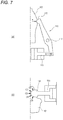
- FIG. 7 depicts an example of a link member of a reference example.
- FIG. 8 depicts a modified embodiment.
- FIG. 1 depict a resin container 1 manufactured by a blow molding apparatus and a blow molding method relating to the present invention.
- the resin container 1 is formed of a resin material such as polyethylene terephthalate, and is used as a container for storing or transporting seasonings, beverages, alcoholic liquors and the like, for example.
- the resin container 1 has a neck part 11 having an opening formed at an upper end, a tubular body part 12 , a shoulder part 13 configured to connect the neck part 11 and the body part 12 by enlarging diameters thereof, a bottom part 14 formed at a lower end, and a heel part 15 configured to connect the bottom part 14 and the body part 12 by enlarging diameters thereof.
- the body part 12 of the resin container 1 is provided with a grip part 20 .
- the broken line in ( a ) to ( c ) of FIG. 1 indicates a preform P that is used to manufacture the resin container 1 .
- the preform P has a neck part having the same shape as the resin container 1 , a substantially cylindrical body part, and a substantially semispherical bottom part, and has a bottomed tubular shape.
- the grip part 20 is formed from the shoulder part 13 toward the lower of the body part 12 at a rear side of the resin container 1 in a height direction of the resin container 1 .
- the grip part 20 is formed to continue to an outer peripheral surface of the resin container 1 .
- the grip part 20 is formed to have an outer peripheral surface having substantially the same outer diameter as an outer peripheral surface of the body part 12 formed at upper and lower sides of the grip part 20 at a rear side of the body part 12 .
- the grip part 20 is formed to have an outer peripheral surface more recessed to an inner side of the resin container 1 than the outer peripheral surface of the body part 12 at left and right side surfaces of the body part 12 .
- a front side (a central axis O-side of the resin container 1 ) of the grip part 20 is formed with a first concave part 22 on a left side surface and a second concave part 23 on a right side surface, which are recessed toward the inner side of the resin container 1 and face each other.
- the first concave part 22 and the second concave part 23 are provided as a concave part for grip when gripping the grip part 20 , and are formed at positons that are substantially flush with the grip part 20 .
- the first concave part 22 has a front surface part 22 a and a rear surface part 22 b , which are inclined from one side surface of the resin container 1 toward the inner side of the resin container 1 , and a bottom part 22 c formed between the front surface part 22 a and the rear surface part 22 b .
- the second concave part 23 has a front surface part 23 a and a rear surface part 23 b , which are inclined from an opposite side surface to the one side surface of the resin container 1 toward the inner side of the resin container 1 , and a bottom part 23 c formed between the front surface part 23 a and the rear surface part 23 b .
- the first concave part 22 and the second concave part 23 are formed so that the bottom part 22 c and the bottom part 23 c face each other.
- the rear surface part 22 b of the first concave part 22 and the rear surface part 23 b of the second concave part 23 define an outer peripheral surface of a front side of the grip part 20 .
- the bottom part 22 c and the bottom part 23 c are welded on the opposing surfaces thereof (refer to the broken line).
- the bottom part 22 c and the bottom part 23 may be separated and in contact with each other at the opposing surfaces thereof.
- a blow molding apparatus 30 includes an injection molding part 40 for manufacturing a preform, and a temperature adjustment part 45 for adjusting a temperature of the manufactured preform.
- the injection molding part 40 is connected with an injection apparatus 42 configured to supply a resin material, which is a source material.
- the blow molding apparatus 30 includes a blow molding part (an example of the blow apparatus) 50 for blowing the preform to manufacture the resin container 1 having the grip part 20 and a take-out part 55 for taking out the manufactured resin container 1 .
- the injection molding part 40 , the temperature adjustment part 45 , the blow molding part 50 and the take-out part 55 are provided at positions rotated by predetermined angles (90°, in this example) about conveying means 60 .
- the conveying means 60 is configured by a rotating plate and the like. A molded product of which the neck part 11 is supported by a neck mold mounted to the rotating plate is conveyed to each part in association with rotation of the rotating plate.
- the injection molding part 40 includes an injection cavity mold, an injection core mold, a neck mold and the like, which are not shown.
- a resin material is caused to flow from the injection apparatus 42 into a preform-shaped space, which is formed as the molds are mold-clamped, so that a bottomed tubular preform is manufactured.
- the temperature adjustment part 45 is configured to heat and adjust a temperature of the preform P manufactured with the injection molding part 40 to a temperature suitable for stretching blowing.
- the temperature adjustment part 45 may be any type of a temperature adjustment pot type, an infrared heater type, a RED type and an electromagnetic heating type.
- the take-out part 55 is configured to take out the resin container 1 by opening the neck part 11 of the resin container 1 manufactured in the blow molding part 50 from the neck mold.
- the blow molding part 50 includes a blow cavity mold 70 having two split molds 71 , link members 80 for forming the grip part 20 , and piston members 90 configured to press the link members 80 .
- the split mold 71 is fixed to a blow base 73 on a surface on which the piston member 90 is provided, and the blow base 73 is coupled to a mold clamping device 51 to be openable and closable.
- a lower part of the blow cavity mold 70 is provided with a bottom mold and an upper part of the blow cavity mold 70 is provided with a blow core mold to be vertically moveable.
- a broken line at a substantially center position of the blow cavity mold 70 indicates the preform P before the blow molding.
- the blow cavity mold 70 is configured to accommodate therein the injection-molded preform P, and to define an outer peripheral surface of the preform P (the resin container 1 ) to be subjected to the blow molding.
- the link member 80 is provided to each of the split molds 71 of the blow cavity mold 70 so that it can rotate about a shaft part 81 .
- a recess part (concave part) 72 is formed on a side surface of the split mold 71 perpendicular to a parting line (PL), and the shaft part 81 for pivotally supporting the link member 80 is provided at a part closer to the parting line than a center of the recess part 72 .
- the link member 80 can rotate from a standby position as shown in FIG. 3 at which the link member is distant from a center of a cavity (space) 70 a of the blow cavity mold 70 to a pressurizing position as shown in FIG.
- An elastic member (for example, a coil spring such as tension spring) 87 is provided between the link member 80 and the split mold 71 of the blow cavity mold, so that while the blow molding is not performed, the link member 80 is arranged at the standby position by an elastic force of the elastic member 87 .
- the link member 80 has a long link main body part 82 having a substantially L-shape and a mold insert 84 fixed to one end portion (link end portion) 83 of the link main body part 82 .
- An end portion of the link member 80 which is opposite to the link end portion 83 having the mold insert 84 fixed thereto, is configured as the shaft part 81 .
- the link end portion 83 and the mold insert 84 are collectively referred to as a grip forming part 85 of the link member 80 .
- the link member 80 is configured to pressurize a portion of the preform P, which is expanded during the blow molding, by the protruding grip forming part 85 , thereby forming the grip part 20 at a portion of the resin container 1 .
- the mold insert 84 is provided at a long side part 82 a of the link member 80 having a substantially L-shape, and the shaft part 81 is provided at a short side part 82 b.
- the grip forming part 85 has a pressurizing surface 85 a configured to pressurize the preform P and a contact surface 85 b configured to come into contact with the piston member 90 when pressed by the piston member 90 .
- the pressurizing surface 85 a of the grip forming part 85 is arranged at an opposite side to the contact surface 85 b of the grip forming part 85 with respect to a moving direction of the piston member 90 .
- the pressurizing surface 85 a is arranged on substantially the same surface as an inner wall surface of the cavity 70 a (refer to FIG. 3 ), and when the link member 80 is located at the pressurizing position, the pressurizing surface 85 a is arranged in the cavity 70 a (refer to FIG. 4 ).
- the piston member 90 is arranged in a tubular cylinder 95 mounted to the blow cavity mold 70 , and is configured to move forward and rearward with respect to the cavity 70 a of the blow cavity mold 70 .
- the piston member 90 has a piston base 91 configured to slide in the cylinder 95 and to move forward and rearward with respect to the cavity 70 a , and a piston rod 92 extending from the piston base 91 toward the cavity 70 a.
- a leading end face of the piston rod 92 is formed as a pressing surface 92 a configured to contact the contact surface 85 b of the grip forming part 85 and to press the grip forming part 85 . That is, the piston rod 92 and the grip forming part 85 are not coupled to each other by any coupling member, and are instead configured so that the leading end face of the piston rod 92 is just supported in a non-coupling manner to the contact surface 85 b of the grip forming part 85 rotated in a direction of getting away from the center of the cavity 70 a by the elastic force of the elastic member 87 .
- the pressing surface 92 a presses the grip forming part 85 to move the pressurizing surface 85 a of the grip forming part 85 from the standby position to the pressurizing position, the pressing surface 92 a changes a contact position while sliding relative to the contact surface 85 b of the grip forming part 85 , thereby pressing the grip forming part 85 toward an inside of the cavity 70 a.
- the bottomed tubular preform P is manufactured by mold-clamping the injection core mold and the injection cavity mold to the neck mold and injecting a resin material from the injection apparatus 42 into the mold (step S 101 ).
- the injection core mold is retreated to mold-open the injection cavity mold, and the preform P is conveyed to the temperature adjustment part 45 in a state where the neck part of the preform P is held by the neck mold (step S 102 ).
- the preform P is inserted in the temperature adjustment pot, for example, and a temperature of the preform P is adjusted to a temperature suitable for stretching (step S 103 ).
- the preform P is taken out from the temperature adjustment pot, and is conveyed to the blow molding part 50 (step S 104 ).
- the blow core mold is inserted into the preform P held by the neck mold, the blow cavity mold 70 is mold-clamped and the bottom mold is mounted, so that the preform P is arranged in the cavity 70 a (step S 105 ).
- the blow air is introduced into the preform P from the blow core mold to blow-mold the preform P into a shape of the cavity 70 a .
- the piston base 91 of the piston member 90 provided to the split mold 71 is moved forward toward the cavity 70 a .
- the piston base 91 is moved forward, so that the pressing surface 92 a of the piston rod 92 comes into contact with the contact surface 85 b of the grip forming part 85 and presses the grip forming part 85 toward the inside of the cavity 70 a .
- the link member 80 is rotated, so that the pressurizing surface 85 a of the grip forming part 85 is moved from the standby position (refer to FIG. 3 ) to the pressurizing position (refer to FIG. 4 ).
- the similar operation is also performed in the other split mold 71 of the blow molding part 50 .
- the first concave part 22 and the second concave part 23 are formed to the body part 12 of the blown preform P (resin container 1 ).
- the first concave part 22 and the second concave part 23 are formed, so that the grip part 20 of which the outer peripheral surface of the front side is defined by the rear surface part 22 b of the first concave part 22 and the rear surface part 23 b of the second concave part 23 is formed (step S 106 ),
- blow cavity mold 70 the blow core mold and the bottom mold are mold-opened, and the resin container 1 blow-molded is conveyed while being held by the neck mold to the take-out part 55 (step S 107 ).
- step S 108 the manufacturing of the resin container 1 is completed.
- the step of manufacturing the preform P may be any step capable of preparing the preform P to be blow-molded, for example, a step of conveying the preform P manufactured at other place.
- the resin container having the grip part has become larger.
- a moveable mold insert is mounted so as to form a concave part for finger-hooking, in many cases.
- one end of a link member 110 is provided with a mold insert 111 for forming a grip part, and the other end of the link member 110 is provided with a hydraulic cylinder 113 for rotating the link member 110 with a shaft part 112 being interposed therebetween.
- a force of the blow air (an arrow A) for expanding a preform 100 is applied to the mold insert 111 provided at one end, and a force of the hydraulic cylinder (an arrow B) for rotating the link member 110 is applied to the other end.
- the force of the blow air and the force of the hydraulic cylinder are separately applied in the same direction to both sides of the link member 110 having the shaft part 112 interposed therebetween. Accordingly, defects such as damage or failure is likely to occur to the respective parts of the link member 110 including the mold insert 111 and the shaft part 112 .
- a mold insert 121 is coaxially coupled integrally with a hydraulic cylinder 123 .
- the force of the blow air for expanding the preform 101 has an influence on the mold insert 121 in irregular directions, as shown with arrows C 1 , C 2 , . . . , C 5 .
- the force of the blow air may act on the advancing movement of the hydraulic cylinder 123 so that it deviates (oscillates) in a vertical direction or in a right and left direction.
- the hydraulic cylinder 123 frictions a peripheral part, so that defects such as damage or failure occurs.
- the pressurizing surface 85 a of the grip forming part 85 of the link member 80 is arranged at the opposite side of the contact surface 85 b of the grip forming part 85 with respect to the moving direction of the piston member 90 .
- a place at which force is applied to the link member 80 during the blow molding is the pressurizing surface 85 a facing toward the cavity 70 a , to which the force of the blow air for expanding the preform P is applied, and the contact surface 85 b facing toward the piston member 90 , to which the force for rotating the link member 80 (the force from the piston member 90 ) is applied.
- the grip forming part 85 of the link member 80 and the piston member 90 are independent members and are not coupled to each other. For this reason, during the blow molding, the pressing surface 92 a of the piston member 90 changes a contact position and presses the grip forming part while sliding relative to the contact surface 85 b of the grip forming part 85 , thereby moving the grip forming part 85 from the standby position to the pressurizing position. That is, it is possible to move the grip forming part (link member) in conformity to a necessary stroke even though a coupling member is not arranged between the link member 80 having the grip forming part and the piston member 90 . Accordingly, it is possible to completely eliminate a risk of a damage or failure of the coupling member and a maintenance operation thereof. Also, since the number of components is reduced, it is possible to save the cost of the mold (blow mold).
- the link member 80 is arranged at the standby position by the elastic member 87 .
- the grip forming part 85 is suppressed from unnecessarily protruding into the cavity 70 a of the blow cavity mold 70 , at times other than the forming of the grip.
- the present invention is not limited to the above illustrative embodiment and can be appropriately modified and improved.
- the materials, shapes, sizes, numerical values, forms, numbers, arrangement places and the like of the respective constitutional elements of the illustrative embodiment are arbitrary and are not particularly limited inasmuch as the present invention can be implemented.
- a blow molding apparatus 30 A may have a configuration where the injection molding part 40 and the blow molding part 50 are connected using a conveyor rail.
- the conveyor rail is configured to continuously convey a conveyance jig supporting the preform P in a loop shape, and a temperature adjustment part 45 A (a heating part) may be provided on the way of a path of the conveyor rail (in the meantime, since a configuration of the blow molding apparatus 30 A has been already known in WO2012/057016 filed by the applicant of this application, for example, only a brief description thereof is provided here).
- a plurality of the blow cavity molds 70 may be aligned in a direction along the parting line within a length range of the mold clamping device 51 .
- blow molding part an example of the blow apparatus
Abstract
Description
-
- a pressurizing surface configured to pressurize the portion of the preform that is expanded during the blow molding; and
- a contact surface configured to come into contact with the piston member,
Claims (4)
Applications Claiming Priority (3)
| Application Number | Priority Date | Filing Date | Title |
|---|---|---|---|
| JP2015211770 | 2015-10-28 | ||
| JP2015-211770 | 2015-10-28 | ||
| PCT/JP2016/081968 WO2017073699A1 (en) | 2015-10-28 | 2016-10-27 | Metal mould, blow moulding apparatus, and blow moulding method |
Publications (2)
| Publication Number | Publication Date |
|---|---|
| US20180304519A1 US20180304519A1 (en) | 2018-10-25 |
| US10773445B2 true US10773445B2 (en) | 2020-09-15 |
Family
ID=58631716
Family Applications (1)
| Application Number | Title | Priority Date | Filing Date |
|---|---|---|---|
| US15/771,789 Active 2037-07-08 US10773445B2 (en) | 2015-10-28 | 2016-10-27 | Mold, blow molding apparatus, and blow molding method |
Country Status (5)
| Country | Link |
|---|---|
| US (1) | US10773445B2 (en) |
| EP (1) | EP3369551B8 (en) |
| JP (1) | JP6796592B2 (en) |
| CN (1) | CN108349148B (en) |
| WO (1) | WO2017073699A1 (en) |
Families Citing this family (6)
| Publication number | Priority date | Publication date | Assignee | Title |
|---|---|---|---|---|
| US11007701B2 (en) | 2016-10-12 | 2021-05-18 | Nissei Asb Machine Co., Ltd. | Blow mold |
| WO2018225734A1 (en) | 2017-06-09 | 2018-12-13 | 日精エー・エス・ビー機械株式会社 | Mold |
| FR3088572B1 (en) * | 2018-11-20 | 2020-10-16 | Sidel Participations | A method of manufacturing a plastic container with a handle obtained by boxing. |
| EP4029671A4 (en) * | 2019-09-12 | 2023-09-27 | Nissei Asb Machine Co., Ltd. | Method for producing resin container and apparatus for producing resin container |
| JP6999768B1 (en) * | 2020-09-28 | 2022-01-19 | 銓寶工業股▲分▼有限公司 | Temperature control device and blow molding machine |
| JP6985478B1 (en) * | 2020-09-28 | 2021-12-22 | 銓寶工業股▲分▼有限公司 | Blow molding method for bottles with handles |
Citations (11)
| Publication number | Priority date | Publication date | Assignee | Title |
|---|---|---|---|---|
| FR1503960A (en) * | 1966-10-20 | 1967-12-01 | Method and mold for making a hollow plastic part comprising a spacer or other member extending inside | |
| DE19627805A1 (en) * | 1995-07-12 | 1997-02-06 | Corelco | Moulding plant esp. for high viscosity plastics |
| JPH11314268A (en) | 1998-05-07 | 1999-11-16 | Pioneer Kogyo Kk | Blow molding die for biaxially stretched bottle with grip |
| JP2000246790A (en) | 1999-03-03 | 2000-09-12 | Sahara Kagaku Kogyo Kk | Bottle for carbonated beverage, and its manufacture |
| EP1616688A2 (en) | 2004-07-14 | 2006-01-18 | Delta Engineering | Method for blow moulding objects |
| CN1822934A (en) | 2003-06-19 | 2006-08-23 | 西德尔公司 | Moulding device for the production of containers in thermoplastic material |
| CN1826266A (en) | 2004-05-19 | 2006-08-30 | 日精Asb机械株式会社 | Stretch blow molding method for grippable bottle |
| JP2007153366A (en) | 2005-12-02 | 2007-06-21 | Nissei Asb Mach Co Ltd | Heat-resistant container, heat-resistant container with content, and manufacturing method for heat-resistant container |
| WO2007082051A1 (en) | 2006-01-11 | 2007-07-19 | Graham Packaging Company, L.P. | Method and apparatus for forming stretch blow molded containers |
| US20080124424A1 (en) | 2006-11-28 | 2008-05-29 | Sidel Participations | Installation for blow-molding hollow bodies |
| WO2010015219A2 (en) | 2008-08-05 | 2010-02-11 | Khs Corpoplast Gmbh & Co. Kg | Method and apparatus for blow molding receptacles |
-
2016
- 2016-10-27 US US15/771,789 patent/US10773445B2/en active Active
- 2016-10-27 EP EP16859928.0A patent/EP3369551B8/en active Active
- 2016-10-27 WO PCT/JP2016/081968 patent/WO2017073699A1/en active Application Filing
- 2016-10-27 JP JP2017547870A patent/JP6796592B2/en active Active
- 2016-10-27 CN CN201680063749.8A patent/CN108349148B/en active Active
Patent Citations (13)
| Publication number | Priority date | Publication date | Assignee | Title |
|---|---|---|---|---|
| FR1503960A (en) * | 1966-10-20 | 1967-12-01 | Method and mold for making a hollow plastic part comprising a spacer or other member extending inside | |
| DE19627805A1 (en) * | 1995-07-12 | 1997-02-06 | Corelco | Moulding plant esp. for high viscosity plastics |
| JPH11314268A (en) | 1998-05-07 | 1999-11-16 | Pioneer Kogyo Kk | Blow molding die for biaxially stretched bottle with grip |
| JP2000246790A (en) | 1999-03-03 | 2000-09-12 | Sahara Kagaku Kogyo Kk | Bottle for carbonated beverage, and its manufacture |
| US20070026098A1 (en) | 2003-06-19 | 2007-02-01 | Eric Lemaistre | Moulding device for the production of containers in thermoplastic material |
| CN1822934A (en) | 2003-06-19 | 2006-08-23 | 西德尔公司 | Moulding device for the production of containers in thermoplastic material |
| CN1826266A (en) | 2004-05-19 | 2006-08-30 | 日精Asb机械株式会社 | Stretch blow molding method for grippable bottle |
| EP1616688A2 (en) | 2004-07-14 | 2006-01-18 | Delta Engineering | Method for blow moulding objects |
| JP2007153366A (en) | 2005-12-02 | 2007-06-21 | Nissei Asb Mach Co Ltd | Heat-resistant container, heat-resistant container with content, and manufacturing method for heat-resistant container |
| WO2007082051A1 (en) | 2006-01-11 | 2007-07-19 | Graham Packaging Company, L.P. | Method and apparatus for forming stretch blow molded containers |
| US20080124424A1 (en) | 2006-11-28 | 2008-05-29 | Sidel Participations | Installation for blow-molding hollow bodies |
| CN100594115C (en) | 2006-11-28 | 2010-03-17 | 赛德尔参与公司 | Installation for blow-molding hollow bodies |
| WO2010015219A2 (en) | 2008-08-05 | 2010-02-11 | Khs Corpoplast Gmbh & Co. Kg | Method and apparatus for blow molding receptacles |
Non-Patent Citations (4)
| Title |
|---|
| English-language International Search Report issued by the Japan Patent Office in International Application No. PCT/JP2016/081968, dated Dec. 6, 2016. |
| First Chinese Office Action Issued by the State Intellectual Property Office of People's Republic of China in corresponding Chinese Application No. 201680063749.8, dated Sep. 4, 2019 (11 pages). |
| Partial machine translation of JP 11-314268 A dated Nov. 1999 obtained from the espace website. (Year: 1999). * |
| Supplementary European Search Report issued in counterpart European Application No. 16859928.0, dated Apr. 10, 2019. |
Also Published As
| Publication number | Publication date |
|---|---|
| EP3369551A4 (en) | 2019-05-08 |
| US20180304519A1 (en) | 2018-10-25 |
| JPWO2017073699A1 (en) | 2018-08-16 |
| EP3369551B8 (en) | 2021-04-28 |
| CN108349148B (en) | 2020-07-31 |
| EP3369551A1 (en) | 2018-09-05 |
| WO2017073699A1 (en) | 2017-05-04 |
| EP3369551B1 (en) | 2021-03-17 |
| CN108349148A (en) | 2018-07-31 |
| JP6796592B2 (en) | 2020-12-09 |
Similar Documents
| Publication | Publication Date | Title |
|---|---|---|
| US10773445B2 (en) | Mold, blow molding apparatus, and blow molding method | |
| US11731337B2 (en) | Blow molding device and blow molding method | |
| US11472091B2 (en) | Two step blow molding unit, apparatus and method | |
| KR101915303B1 (en) | Injection blow molding device, mold unit used therefor, and injection blow molding method | |
| WO2014203975A1 (en) | Conveyance device | |
| JP6448608B2 (en) | Mold unit for blow molding | |
| JP2022168283A (en) | Method for manufacturing eccentric container, and mold for temperature control | |
| WO2015025797A1 (en) | Process for producing container with handle, apparatus for producing container with handle, and container with handle | |
| WO2015147207A1 (en) | Molding die unit and manufacturing device for container with handle | |
| KR101406300B1 (en) | Equipment formation of handle receptacle p.e.t | |
| US11007701B2 (en) | Blow mold | |
| JP7254781B2 (en) | blow molding machine | |
| JP7179741B2 (en) | Blow molding apparatus and blow molding method | |
| JP7112395B2 (en) | Mold | |
| JP7190788B1 (en) | Method for manufacturing resin container | |
| US11964793B2 (en) | Resin-made container, resin-made container manufacturing method, resin-made container manufacturing apparatus, and mold | |
| TWI714171B (en) | Mold for blow molding, method for manufacturing resin container using the mold, and resin container | |
| WO2021221024A1 (en) | Method for manufacturing resin wide-mouthed container, manufacturing device, and resin wide-mouthed container | |
| US20230339166A1 (en) | Blow molding apparatus |
Legal Events
| Date | Code | Title | Description |
|---|---|---|---|
| FEPP | Fee payment procedure |
Free format text: ENTITY STATUS SET TO UNDISCOUNTED (ORIGINAL EVENT CODE: BIG.); ENTITY STATUS OF PATENT OWNER: LARGE ENTITY |
|
| AS | Assignment |
Owner name: NISSEI ASB MACHINE CO., LTD., JAPAN Free format text: ASSIGNMENT OF ASSIGNORS INTEREST;ASSIGNOR:USAMI, MASAYUKI;REEL/FRAME:045665/0929 Effective date: 20180412 |
|
| STPP | Information on status: patent application and granting procedure in general |
Free format text: DOCKETED NEW CASE - READY FOR EXAMINATION |
|
| STPP | Information on status: patent application and granting procedure in general |
Free format text: RESPONSE TO NON-FINAL OFFICE ACTION ENTERED AND FORWARDED TO EXAMINER |
|
| STPP | Information on status: patent application and granting procedure in general |
Free format text: NOTICE OF ALLOWANCE MAILED -- APPLICATION RECEIVED IN OFFICE OF PUBLICATIONS |
|
| STPP | Information on status: patent application and granting procedure in general |
Free format text: PUBLICATIONS -- ISSUE FEE PAYMENT VERIFIED |
|
| STCF | Information on status: patent grant |
Free format text: PATENTED CASE |
|
| MAFP | Maintenance fee payment |
Free format text: PAYMENT OF MAINTENANCE FEE, 4TH YEAR, LARGE ENTITY (ORIGINAL EVENT CODE: M1551); ENTITY STATUS OF PATENT OWNER: LARGE ENTITY Year of fee payment: 4 |