US10769902B1 - Systems and methods for dynamic building evacuation - Google Patents
Systems and methods for dynamic building evacuation Download PDFInfo
- Publication number
- US10769902B1 US10769902B1 US16/002,713 US201816002713A US10769902B1 US 10769902 B1 US10769902 B1 US 10769902B1 US 201816002713 A US201816002713 A US 201816002713A US 10769902 B1 US10769902 B1 US 10769902B1
- Authority
- US
- United States
- Prior art keywords
- evacuation
- signal
- control unit
- building
- local control
- Prior art date
- Legal status (The legal status is an assumption and is not a legal conclusion. Google has not performed a legal analysis and makes no representation as to the accuracy of the status listed.)
- Active
Links
- 238000000034 method Methods 0.000 title abstract description 6
- 239000000779 smoke Substances 0.000 claims description 42
- 230000004044 response Effects 0.000 claims description 6
- 230000001953 sensory effect Effects 0.000 claims 1
- 238000001514 detection method Methods 0.000 abstract description 9
- JLQUFIHWVLZVTJ-UHFFFAOYSA-N carbosulfan Chemical compound CCCCN(CCCC)SN(C)C(=O)OC1=CC=CC2=C1OC(C)(C)C2 JLQUFIHWVLZVTJ-UHFFFAOYSA-N 0.000 description 8
- 238000003619 Marshal aromatic alkylation reaction Methods 0.000 description 2
- 230000004913 activation Effects 0.000 description 2
- 238000010586 diagram Methods 0.000 description 2
- 239000000463 material Substances 0.000 description 2
- 231100000279 safety data Toxicity 0.000 description 2
- 230000003068 static effect Effects 0.000 description 2
- 230000002159 abnormal effect Effects 0.000 description 1
- 230000002547 anomalous effect Effects 0.000 description 1
- 230000001413 cellular effect Effects 0.000 description 1
- 230000000739 chaotic effect Effects 0.000 description 1
- 239000003086 colorant Substances 0.000 description 1
- 230000000694 effects Effects 0.000 description 1
- 238000005286 illumination Methods 0.000 description 1
- 230000000977 initiatory effect Effects 0.000 description 1
- 238000009434 installation Methods 0.000 description 1
- 239000013618 particulate matter Substances 0.000 description 1
- 230000001902 propagating effect Effects 0.000 description 1
- 239000007787 solid Substances 0.000 description 1
- 238000001228 spectrum Methods 0.000 description 1
Images


Classifications
-
- G—PHYSICS
- G08—SIGNALLING
- G08B—SIGNALLING OR CALLING SYSTEMS; ORDER TELEGRAPHS; ALARM SYSTEMS
- G08B7/00—Signalling systems according to more than one of groups G08B3/00 - G08B6/00; Personal calling systems according to more than one of groups G08B3/00 - G08B6/00
- G08B7/06—Signalling systems according to more than one of groups G08B3/00 - G08B6/00; Personal calling systems according to more than one of groups G08B3/00 - G08B6/00 using electric transmission, e.g. involving audible and visible signalling through the use of sound and light sources
- G08B7/066—Signalling systems according to more than one of groups G08B3/00 - G08B6/00; Personal calling systems according to more than one of groups G08B3/00 - G08B6/00 using electric transmission, e.g. involving audible and visible signalling through the use of sound and light sources guiding along a path, e.g. evacuation path lighting strip
-
- G—PHYSICS
- G08—SIGNALLING
- G08B—SIGNALLING OR CALLING SYSTEMS; ORDER TELEGRAPHS; ALARM SYSTEMS
- G08B17/00—Fire alarms; Alarms responsive to explosion
- G08B17/10—Actuation by presence of smoke or gases, e.g. automatic alarm devices for analysing flowing fluid materials by the use of optical means
- G08B17/103—Actuation by presence of smoke or gases, e.g. automatic alarm devices for analysing flowing fluid materials by the use of optical means using a light emitting and receiving device
-
- G—PHYSICS
- G08—SIGNALLING
- G08B—SIGNALLING OR CALLING SYSTEMS; ORDER TELEGRAPHS; ALARM SYSTEMS
- G08B21/00—Alarms responsive to a single specified undesired or abnormal condition and not otherwise provided for
- G08B21/02—Alarms for ensuring the safety of persons
- G08B21/12—Alarms for ensuring the safety of persons responsive to undesired emission of substances, e.g. pollution alarms
-
- G—PHYSICS
- G08—SIGNALLING
- G08B—SIGNALLING OR CALLING SYSTEMS; ORDER TELEGRAPHS; ALARM SYSTEMS
- G08B7/00—Signalling systems according to more than one of groups G08B3/00 - G08B6/00; Personal calling systems according to more than one of groups G08B3/00 - G08B6/00
- G08B7/06—Signalling systems according to more than one of groups G08B3/00 - G08B6/00; Personal calling systems according to more than one of groups G08B3/00 - G08B6/00 using electric transmission, e.g. involving audible and visible signalling through the use of sound and light sources
- G08B7/062—Signalling systems according to more than one of groups G08B3/00 - G08B6/00; Personal calling systems according to more than one of groups G08B3/00 - G08B6/00 using electric transmission, e.g. involving audible and visible signalling through the use of sound and light sources indicating emergency exits
-
- H—ELECTRICITY
- H04—ELECTRIC COMMUNICATION TECHNIQUE
- H04W—WIRELESS COMMUNICATION NETWORKS
- H04W4/00—Services specially adapted for wireless communication networks; Facilities therefor
- H04W4/30—Services specially adapted for particular environments, situations or purposes
- H04W4/38—Services specially adapted for particular environments, situations or purposes for collecting sensor information
-
- G—PHYSICS
- G08—SIGNALLING
- G08B—SIGNALLING OR CALLING SYSTEMS; ORDER TELEGRAPHS; ALARM SYSTEMS
- G08B25/00—Alarm systems in which the location of the alarm condition is signalled to a central station, e.g. fire or police telegraphic systems
- G08B25/12—Manually actuated calamity alarm transmitting arrangements emergency non-personal manually actuated alarm, activators, e.g. details of alarm push buttons mounted on an infrastructure
Landscapes
- General Physics & Mathematics (AREA)
- Physics & Mathematics (AREA)
- Business, Economics & Management (AREA)
- Emergency Management (AREA)
- Chemical & Material Sciences (AREA)
- Engineering & Computer Science (AREA)
- Analytical Chemistry (AREA)
- Toxicology (AREA)
- General Health & Medical Sciences (AREA)
- Environmental & Geological Engineering (AREA)
- Health & Medical Sciences (AREA)
- Computer Networks & Wireless Communication (AREA)
- Signal Processing (AREA)
- Alarm Systems (AREA)
- Fire Alarms (AREA)
Abstract
A disclosure and claims to systems and methods for allowing rapid detection and display of an emergency condition using a plurality of specially-constructed multifunction sensors and display units, which allow building evacuation plans to be evaluated, modified, and transmitted to building occupants.
Description
The embodiments described herein relate to the field of building safety systems and methods, in particular, building evacuation systems and methods.
Currently, building fire detection systems allow building managers to detect an emergency condition using installed smoke alarms and pull stations which allow both manual and automatic detection of a fire condition. Once a fire or emergency condition is detected, fire alarms or other alerts signal building occupants to either evacuate or shelter in place. However, current building evacuation systems have static evacuation plans that cannot be changed to reflect the realities of an emergency situation. These plans usually involve the building occupants proceeding directly to the nearest building exit, or in multi-story buildings, stairwells leading to the nearest building exit. One major problem with this is that a fire can in theory occur anywhere, including on an evacuation route. In this case, a pre -rehearsed evacuation route can actually put evacuees in greater danger. Another issue is that the location of building occupants may not be accurately known. Yet another issue is that the precise location and nature of an emergency condition may not be immediately known. For example, fire alarms can be activated manually, and the location of the fire alarm, i.e. pull station that was activated gives an indication that the emergency condition is occurring in the vicinity of that particular alarm, but does not localize the source with any accuracy, nor does it indicate the exact nature of the emergency condition. Similarly, detectors that automatically alert in the presence of smoke are strong indicators that a fire is present, but do not permit the location of the fire to be determined precisely, since smoke can travel for some distance in a building before being detected.
Embodiments disclosed describe systems and methods of detecting the nature and location of an emergency condition rapidly using a distributed network of sensor and signal units and pull stations that are in communication with local control units and remote control stations. The local control units and remote control stations are comprised in part of computational resources which analyze existing evacuation plans and, if necessary, provide the capability of changing such evacuation plans in real time. The sensor and signal units and pull stations enhance the capabilities of convention installed smoke alarms and pull stations to include not only sensors, but multifunction displays or signals so that customized evacuation routes can be quickly communicated to evacuees.
The sensor and signal units feature a signal or display apparatus and at least a smoke detector that may be recessed into the ceiling to enhance smoke detection. The signal or display apparatus features
either an array of LED lights or a multifunction display that are bright enough to be viewed in low- visibility (e.g. smoky) conditions. For example, one embodiment of the system consists of a distributed network of temperature, humidity, motion, smoke, and sound detectors embedded in fire pull stations and sensor and signal units located on wall and ceilings, respectively. These distributed sensors detect indications across a wide spectrum (e.g. infrared, moisture, particulate matter, and pressure wave) and transmit anomalous data to a data processing station located within a building. The local control unit located within a building is networked with a remote control station that is typically collocated with a municipal fire authority. Either the local control unit or remote control station are capable of autonomously processing the sensor network data and evaluating the predefined building evacuation route to determine whether the source of the emergency is located in the path of an evacuation route. If it is, an alternate route can be automatically generated to avoid the emergency source. This alternate route is transmitted to the sensor and signal units and pull station, which display either text, symbols, or patterns directing evacuees along the appropriate evacuation route. An alternate building evacuation route can also be generated manually by a building fire marshal, municipal fire chief, police on-scene commander, or other authority having jurisdiction on the scene from either the local or remote data processing stations, or from a personal computing device such as a smartphone or tablet device having application software that interfaces via wireless network with the local and remote data processing stations.
The invention is described in preferred embodiments in the following description with reference to the Figures, in which like numbers represent the same or similar elements. Reference throughout this specification to “one embodiment”, “an embodiment”, or similar language means that particular feature, structure, or characteristic described in connection with the embodiment is included in at least one embodiment of the present invention. Thus, appearances of the phrases “in one embodiment”, “in an embodiment”, “in certain embodiments”, and similar language throughout this specification may, but do not necessarily, all refer to the same embodiment. It should be noted that, as used in this description, the singular forms “a”, “an”, and “the” include plural referents unless the context clearly dictates otherwise.
The described features, structures, or characteristics of the invention may be combined in any suitable manner in one or more embodiments. In the following description, numerous specific details are recited to provide a thorough understanding of embodiments of the invention. One skilled in the relevant art will recognize, however, that the invention may be practiced without one or more of the specific details, or with other methods, components, materials, and so forth. In other instances, well-known structures, materials, or operations are not shown or described in detail to avoid obscuring aspects of the invention.
A block diagram of an embodiment of a building dynamic evacuation system 10 is presented in FIG. 1 . Local control unit 12 is located within a building 11 and is connected either via hardwired connections or via a wireless connection to a plurality of pull stations 13, sensor and signal units (SSU) 14, both of which will be described in greater detail herein, and legacy (currently known to the prior art, e.g. smoke or moisture detectors and pull stations without the features described herein) sensors 15 located throughout the building. Local control unit includes a general purpose computer 121, a database 122, and a transceiver 16. Remote control station 20 includes a general purpose computer 201, database 202, transceiver 26, all of which are located at a remote location 30, which could be the office of a municipal fire marshal or other authority having jurisdiction (AHJ). Alternatively, remote control station 20 can be embodied by a portable computing device 19, e.g. a smartphone, tablet computer, or laptop. Local control unit 12 can be connected to remote control station 20 via hardwired connection 17, cellular or RF connection via transceivers 16, 26, or via computer network 18. Portable computing device 19 is connected wirelessly via computer network 18, via standard wireless communications protocols.
Depending on the embodiment, pull station 13 may also contain temperature, humidity, motion, smoke, and sound detectors. Temperature and smoke detectors directly indicate the presence of fire; humidity sensors detect flooding or the activation of a sprinkler system and so could provide indirect indications of a fire condition within a structure. Motion and sound detectors are useful for detecting which portions of the interior of a building are occupied. Motion and sound sensors are also used for detecting signs of criminal or other abnormal activity within the building. Such activity could be indicated by the presence of abnormally loud noises within the structure, e.g. shouting, screams, or gunshots, or running Being able to quickly locate both the emergency event, as well as all inhabitants in the area affected by such event is a paramount factor in developing and executing a dynamic evacuation plan.
temperature, humidity, and smoke detection from pull stations 13 and SSUs 14 is transmitted via hardwired or wireless connections to local control unit 12. Software algorithms running on general purpose computer 121 automatically analyze the received sensor data in relation to parameters stored in database 122 to determine if the threshold conditions for an evacuation are met. If so, fire alarms are activated, and software running on general purpose computer 121 calls the evacuation plan subroutine.
Pull stations 13 and SSUs 14 may contain motion sensors in addition to temperature, humidity, smoke, noise, or pressure sensors. Now referring to FIG. 9 , motion detection data collected from these sensors can be integrated at the local control unit to permit computer 121 to generate a heat-mapped display of areas 91 on the floor plan where motion has been detected, and where the most detected motion has occurred, i.e. the most populated areas on the floor plan. FIG. 10 shows a conventional static building evacuation plan, with arrows 101 showing the evacuation route. The issue with this system is that arrows 102 direct evacuees through an active fire zone in order to reach the escape stairwells 61. However, in embodiments of the current system, software running on general purpose computer 121 at local control unit 12 or general purpose computer 201 at remote control station 20 analyze the data from pull stations 13 and SSUs 14 to locate the fire regions, and compute alternate evacuation routes (indicated by arrows 1101) to avoid affected areas, as illustrated in FIG. 11 . Alternatively, the software running on general purpose computers 121, 201 or personal computing device 19 allow a fire marshal or AHJ to manually change evacuation routes using an input/ output terminal 123, 203 located at either local control unit 12, remote control station 20, or personal computing device 19. The application software ensures that all sensor data received is transmitted to remote control stations 20/personal computing device 19 and displays this as it would be displayed on an output terminal at either local control unit 12 or remote control station 20. Thus, a fire marshal or AHJ can either remotely (i.e. from a remote control station 20 or personal computing device 19) or locally control building evacuation based on information received from pull stations 13 and SSUs 14 located within the building.
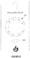
Once the correct evacuation route has either been determined (either automatically or manually), this route must be communicated to evacuees in what is typically a stressful and chaotic situation. As described above and shown in FIGS. 3 and 5 , SSUs 14 incorporate, in addition to a smoke detector 52, a plurality of high-intensity signal lights 53. In one preferred embodiment, signal lights 53 are multicolored LED lights capable of illuminating either red, green, blue, or amber. In this embodiment, signal lights are disposed around the perimeter of signal housing 54 as shown in FIG. 5 . In this embodiment, signal housing is circular, so that the signal lights 53 are disposed on a 360 degree arc, i.e. visible from all directions. Different patterns of illumination are possible in response to signals sent in response to the customized evacuation plan generated at local control unit 12, personal computing device 19, or remote control station 20. For example, FIG. 12 is an overhead view of signal housing 54 for a fire evacuation
scenario. From the perspective of evacuee 1201, the green signal lights marked “G” in FIG. 12 indicate the correct evacuation route, while red signal lights marked “R” indicate the wrong direction. FIG. 13 shows a placement of SSUs 14 at a corridor t-intersection, where the pattern of red and green signal lights on signal housing 54 direct evacuees 1301 away from the fire area 132. In the alternate embodiment shown in FIG. 5 , the multifunction display 57 visible from the direction leading to the fire will display a message such as “WRONG WAY”, “FIRE AHEAD”, “TURN AROUND”, etc. or a corresponding symbol, while the multifunction display 57 direction leading away from the fire may display a message such as “EXIT THIS WAY”, “WAY OUT”, etc. or a symbol (e.g. an arrow) corresponding to these messages.
In some embodiments pull stations 13 incorporate a multifunction display capable of displaying a QR code. An evacuee scanning the QR code using personal computing device 19 will be presented with a building floorplan showing the current evacuation route.
Although the present invention has been described in detail with reference to certain embodiments, one skilled in the art will appreciate that the present invention can be practiced by other than the described embodiments, which have been presented for purposes of illustration and not of limitation. Therefore, the scope of the appended claims should not be limited to the description of the embodiments contained herein.
Claims (3)
1. A building emergency evacuation system comprising:
a plurality of sensor and signal units comprising:
a smoke sensor disposed within a cavity recessed into a ceiling;
a signal housing adapted to accommodate either an array of signal lights or a multifunction display;
a vent section comprising a plurality of vents adapted to permit smoke flow to said smoke sensor disposed in said cavity, said vent section disposed in a connecting structure joining said cavity and said signal housing; and
a microcontroller adapted to (i) receive an evacuation signal; (ii) cause said signal housing to display information-associated with an evacuation route in response to said evacuation signal;
a local control unit comprising a general purpose computer, said local control unit adapted to: (a) autonomously generate an initial evacuation plan in response to an emergency condition, and (b) grant a plurality of access levels to users; and
a remote control station comprising a general purpose computer in communication with said local control unit, said remote control station adapted to permit a user to obtain command access to said local control unit, wherein command access permits said remote control station to (a) manually edit said initial evacuation plan, and (b) transmit an evacuation signal corresponding to the modified evacuation plan to said sensor and signal units.
2. A building evacuation system capable of detecting an evacuation condition and automatically generating an evacuation plan comprising:
a local control unit located within a structure subject to an evacuation condition, said local control unit being adapted to, grant a remote control station authority to access building plans and sensory data, and permit a user to modify an automatically-generated evacuation plan; and
a plurality of sensor and signal units adapted to communicate with said local control unit comprising:
a smoke sensor disposed in a cavity portion recessed into a ceiling;
a signal housing accommodating an array of signal lights, wherein said signal lights are disposed evenly around the periphery of said housing to provide omnidirectional coverage;
a vent section joining said smoke sensor and said housing; and
a microprocessor adapted to convert a modified evacuation plan into a signal light pattern associated with an evacuation route.
3. The system of claim 2 , wherein said signal housing accommodates a plurality of multicolored LED lights disposed omnidirectionally around its perimeter.
Priority Applications (3)
| Application Number | Priority Date | Filing Date | Title |
|---|---|---|---|
| US16/002,713 US10769902B1 (en) | 2018-06-07 | 2018-06-07 | Systems and methods for dynamic building evacuation |
| US17/013,629 US11508223B2 (en) | 2018-06-07 | 2020-09-06 | System and method for dynamic evacuation of buildings |
| US17/988,519 US11948450B2 (en) | 2018-06-07 | 2022-11-16 | Systems and methods for dynamic building evacuation |
Applications Claiming Priority (1)
| Application Number | Priority Date | Filing Date | Title |
|---|---|---|---|
| US16/002,713 US10769902B1 (en) | 2018-06-07 | 2018-06-07 | Systems and methods for dynamic building evacuation |
Related Child Applications (1)
| Application Number | Title | Priority Date | Filing Date |
|---|---|---|---|
| US17/013,629 Continuation US11508223B2 (en) | 2018-06-07 | 2020-09-06 | System and method for dynamic evacuation of buildings |
Publications (1)
| Publication Number | Publication Date |
|---|---|
| US10769902B1 true US10769902B1 (en) | 2020-09-08 |
Family
ID=72289776
Family Applications (3)
| Application Number | Title | Priority Date | Filing Date |
|---|---|---|---|
| US16/002,713 Active US10769902B1 (en) | 2018-06-07 | 2018-06-07 | Systems and methods for dynamic building evacuation |
| US17/013,629 Active US11508223B2 (en) | 2018-06-07 | 2020-09-06 | System and method for dynamic evacuation of buildings |
| US17/988,519 Active US11948450B2 (en) | 2018-06-07 | 2022-11-16 | Systems and methods for dynamic building evacuation |
Family Applications After (2)
| Application Number | Title | Priority Date | Filing Date |
|---|---|---|---|
| US17/013,629 Active US11508223B2 (en) | 2018-06-07 | 2020-09-06 | System and method for dynamic evacuation of buildings |
| US17/988,519 Active US11948450B2 (en) | 2018-06-07 | 2022-11-16 | Systems and methods for dynamic building evacuation |
Country Status (1)
| Country | Link |
|---|---|
| US (3) | US10769902B1 (en) |
Cited By (11)
| Publication number | Priority date | Publication date | Assignee | Title |
|---|---|---|---|---|
| CN111915837A (en) * | 2020-09-18 | 2020-11-10 | 郑州轻工业大学 | Indoor intelligent evacuation navigation system and method |
| US10991216B1 (en) * | 2020-12-04 | 2021-04-27 | Khaled Alali | Auditory and visual guidance system for emergency evacuation |
| US11164432B2 (en) * | 2017-03-15 | 2021-11-02 | Carrier Corporation | System and method for fire sensing and controlling escape path guide signs accordingly |
| US11189141B2 (en) * | 2019-05-24 | 2021-11-30 | Charles Armpriester | Universal threat awareness management system for occupant safety |
| US11238711B2 (en) * | 2018-09-13 | 2022-02-01 | Carrier Corporation | Fire detection system-fire smart signalling for fire equipment |
| GB2599142A (en) * | 2020-09-25 | 2022-03-30 | Connected Innovations Ltd | Fire safety system and method |
| US11323846B2 (en) * | 2018-11-29 | 2022-05-03 | Motorola Solutions, Inc. | Device, system and method for evacuation task management |
| US11508223B2 (en) * | 2018-06-07 | 2022-11-22 | Jason Kronz | System and method for dynamic evacuation of buildings |
| US11514764B2 (en) * | 2019-11-21 | 2022-11-29 | Alarm.Com Incorporated | Smartlock system for improved fire safety |
| US20230132523A1 (en) * | 2021-11-01 | 2023-05-04 | Jpmorgan Chase Bank, N.A. | Systems and methods for wayfinding in hazardous environments |
| US11972681B2 (en) * | 2021-11-01 | 2024-04-30 | Jpmorgan Chase Bank, N.A. | Systems and methods for wayfinding in hazardous environments |
Citations (8)
| Publication number | Priority date | Publication date | Assignee | Title |
|---|---|---|---|---|
| US4301674A (en) * | 1980-01-14 | 1981-11-24 | Haines William H | Smoke detector tester |
| US4754266A (en) * | 1987-01-07 | 1988-06-28 | Shand Kevin J | Traffic director |
| US5565852A (en) * | 1992-11-30 | 1996-10-15 | Sentrol, Inc. | Smoke detector with digital display |
| US5838223A (en) * | 1993-07-12 | 1998-11-17 | Hill-Rom, Inc. | Patient/nurse call system |
| US20090047893A1 (en) * | 2007-08-15 | 2009-02-19 | Larry Zimmerman | Building Plenum |
| US20150070181A1 (en) * | 2013-09-12 | 2015-03-12 | Google Inc. | Detector unit with multiple integrated sensing systems and visually pleasing housing |
| US20150137967A1 (en) * | 2013-07-15 | 2015-05-21 | Oneevent Technologies, Inc. | Owner controlled evacuation system |
| US20160180663A1 (en) * | 2014-12-18 | 2016-06-23 | Hand Held Products, Inc. | Active emergency exit systems for buildings |
Family Cites Families (4)
| Publication number | Priority date | Publication date | Assignee | Title |
|---|---|---|---|---|
| US9541625B2 (en) * | 2011-08-25 | 2017-01-10 | En-Gauge, Inc. | Emergency resource location and status |
| US8884772B1 (en) | 2013-04-30 | 2014-11-11 | Globestar, Inc. | Building evacuation system with positive acknowledgment |
| US11403929B2 (en) * | 2017-09-13 | 2022-08-02 | 4Morr Enterprises IP, LLC | System and method for detecting smoke using a sensor |
| US10769902B1 (en) * | 2018-06-07 | 2020-09-08 | Jason Kronz | Systems and methods for dynamic building evacuation |
-
2018
- 2018-06-07 US US16/002,713 patent/US10769902B1/en active Active
-
2020
- 2020-09-06 US US17/013,629 patent/US11508223B2/en active Active
-
2022
- 2022-11-16 US US17/988,519 patent/US11948450B2/en active Active
Patent Citations (8)
| Publication number | Priority date | Publication date | Assignee | Title |
|---|---|---|---|---|
| US4301674A (en) * | 1980-01-14 | 1981-11-24 | Haines William H | Smoke detector tester |
| US4754266A (en) * | 1987-01-07 | 1988-06-28 | Shand Kevin J | Traffic director |
| US5565852A (en) * | 1992-11-30 | 1996-10-15 | Sentrol, Inc. | Smoke detector with digital display |
| US5838223A (en) * | 1993-07-12 | 1998-11-17 | Hill-Rom, Inc. | Patient/nurse call system |
| US20090047893A1 (en) * | 2007-08-15 | 2009-02-19 | Larry Zimmerman | Building Plenum |
| US20150137967A1 (en) * | 2013-07-15 | 2015-05-21 | Oneevent Technologies, Inc. | Owner controlled evacuation system |
| US20150070181A1 (en) * | 2013-09-12 | 2015-03-12 | Google Inc. | Detector unit with multiple integrated sensing systems and visually pleasing housing |
| US20160180663A1 (en) * | 2014-12-18 | 2016-06-23 | Hand Held Products, Inc. | Active emergency exit systems for buildings |
Cited By (11)
| Publication number | Priority date | Publication date | Assignee | Title |
|---|---|---|---|---|
| US11164432B2 (en) * | 2017-03-15 | 2021-11-02 | Carrier Corporation | System and method for fire sensing and controlling escape path guide signs accordingly |
| US11508223B2 (en) * | 2018-06-07 | 2022-11-22 | Jason Kronz | System and method for dynamic evacuation of buildings |
| US11238711B2 (en) * | 2018-09-13 | 2022-02-01 | Carrier Corporation | Fire detection system-fire smart signalling for fire equipment |
| US11323846B2 (en) * | 2018-11-29 | 2022-05-03 | Motorola Solutions, Inc. | Device, system and method for evacuation task management |
| US11189141B2 (en) * | 2019-05-24 | 2021-11-30 | Charles Armpriester | Universal threat awareness management system for occupant safety |
| US11514764B2 (en) * | 2019-11-21 | 2022-11-29 | Alarm.Com Incorporated | Smartlock system for improved fire safety |
| CN111915837A (en) * | 2020-09-18 | 2020-11-10 | 郑州轻工业大学 | Indoor intelligent evacuation navigation system and method |
| GB2599142A (en) * | 2020-09-25 | 2022-03-30 | Connected Innovations Ltd | Fire safety system and method |
| US10991216B1 (en) * | 2020-12-04 | 2021-04-27 | Khaled Alali | Auditory and visual guidance system for emergency evacuation |
| US20230132523A1 (en) * | 2021-11-01 | 2023-05-04 | Jpmorgan Chase Bank, N.A. | Systems and methods for wayfinding in hazardous environments |
| US11972681B2 (en) * | 2021-11-01 | 2024-04-30 | Jpmorgan Chase Bank, N.A. | Systems and methods for wayfinding in hazardous environments |
Also Published As
| Publication number | Publication date |
|---|---|
| US11948450B2 (en) | 2024-04-02 |
| US20210043053A1 (en) | 2021-02-11 |
| US20230074176A1 (en) | 2023-03-09 |
| US11508223B2 (en) | 2022-11-22 |
Similar Documents
| Publication | Publication Date | Title |
|---|---|---|
| US11948450B2 (en) | Systems and methods for dynamic building evacuation | |
| US11545012B2 (en) | Gunshot detection system with building management system integration | |
| US7199724B2 (en) | Method and apparatus to aide in emergency egress | |
| KR101827733B1 (en) | An intelligence type emergency shunting incitement method and system of the same | |
| KR101705753B1 (en) | Evacuation path guidance system | |
| RU2734161C2 (en) | Public safety network system equipped with portable lights for wireless fire detection and crime prevention | |
| US8085147B2 (en) | Security system including audio alarm detection | |
| KR101772806B1 (en) | Emergency shunting incitement method of automatically transforming escape direction according to fire located, and system of the same | |
| KR101398819B1 (en) | System unite management system for environment monitoring of unattended building | |
| KR101796054B1 (en) | Smart fire perception system using ip network | |
| JP7249260B2 (en) | emergency notification system | |
| KR101828994B1 (en) | Intelligent integrated emergency management system and method | |
| KR101893040B1 (en) | System and method for providing evacuation route | |
| NO317973B1 (en) | Fire alarm and fire alarm system | |
| US11189141B2 (en) | Universal threat awareness management system for occupant safety | |
| CN112817261A (en) | Multi-linkage personnel evacuation system and method in tunnel and storage medium | |
| KR102049087B1 (en) | Disaster alarm system with evacuation guidance function using laser | |
| KR101807265B1 (en) | fire-prevention system possible earthquake observation | |
| KR102049083B1 (en) | Smart emergency light system with guidance function using laser | |
| KR102312310B1 (en) | Fire escape system capable of guidance of evacuation route | |
| KR101763448B1 (en) | System for prevention of disasters | |
| JP2005115797A (en) | Fire alarm equipment | |
| WO2009017628A2 (en) | Programmable, progressive guiding system: apparatus and method | |
| KR20170079165A (en) | fire-prevention system possible earthquake observation | |
| US20230290233A1 (en) | System and method for providing emergency alerts using multi-color light emitting diode notification appliances |
Legal Events
| Date | Code | Title | Description |
|---|---|---|---|
| FEPP | Fee payment procedure |
Free format text: ENTITY STATUS SET TO UNDISCOUNTED (ORIGINAL EVENT CODE: BIG.); ENTITY STATUS OF PATENT OWNER: SMALL ENTITY |
|
| FEPP | Fee payment procedure |
Free format text: ENTITY STATUS SET TO SMALL (ORIGINAL EVENT CODE: SMAL); ENTITY STATUS OF PATENT OWNER: SMALL ENTITY |
|
| STCF | Information on status: patent grant |
Free format text: PATENTED CASE |
|
| MAFP | Maintenance fee payment |
Free format text: PAYMENT OF MAINTENANCE FEE, 4TH YR, SMALL ENTITY (ORIGINAL EVENT CODE: M2551); ENTITY STATUS OF PATENT OWNER: SMALL ENTITY Year of fee payment: 4 |