US10768027B2 - Method and system for monitoring building structures - Google Patents
Method and system for monitoring building structures Download PDFInfo
- Publication number
- US10768027B2 US10768027B2 US16/459,151 US201916459151A US10768027B2 US 10768027 B2 US10768027 B2 US 10768027B2 US 201916459151 A US201916459151 A US 201916459151A US 10768027 B2 US10768027 B2 US 10768027B2
- Authority
- US
- United States
- Prior art keywords
- sensor
- data
- portable computer
- sensor device
- computer device
- Prior art date
- Legal status (The legal status is an assumption and is not a legal conclusion. Google has not performed a legal analysis and makes no representation as to the accuracy of the status listed.)
- Active
Links
- 238000012544 monitoring process Methods 0.000 title claims abstract description 17
- 238000000034 method Methods 0.000 title abstract description 39
- 239000004567 concrete Substances 0.000 claims abstract description 33
- 238000004891 communication Methods 0.000 claims description 32
- 239000004593 Epoxy Substances 0.000 claims description 7
- 239000000463 material Substances 0.000 claims description 5
- 239000002245 particle Substances 0.000 claims description 4
- 239000010426 asphalt Substances 0.000 claims description 2
- 230000015572 biosynthetic process Effects 0.000 claims description 2
- 238000001514 detection method Methods 0.000 claims description 2
- 230000000694 effects Effects 0.000 claims description 2
- 239000012528 membrane Substances 0.000 description 30
- 239000004566 building material Substances 0.000 description 24
- 230000008569 process Effects 0.000 description 19
- 230000003287 optical effect Effects 0.000 description 13
- 239000002184 metal Substances 0.000 description 8
- 229910052751 metal Inorganic materials 0.000 description 8
- 230000007246 mechanism Effects 0.000 description 7
- 238000004806 packaging method and process Methods 0.000 description 7
- 229920003023 plastic Polymers 0.000 description 6
- 239000004033 plastic Substances 0.000 description 5
- 230000007704 transition Effects 0.000 description 5
- 238000010586 diagram Methods 0.000 description 4
- 230000006870 function Effects 0.000 description 4
- 230000004913 activation Effects 0.000 description 3
- 230000000903 blocking effect Effects 0.000 description 3
- 230000008859 change Effects 0.000 description 3
- 238000010276 construction Methods 0.000 description 3
- 238000013461 design Methods 0.000 description 3
- 239000000203 mixture Substances 0.000 description 3
- 238000012986 modification Methods 0.000 description 3
- 230000004048 modification Effects 0.000 description 3
- 230000002093 peripheral effect Effects 0.000 description 3
- 229920001296 polysiloxane Polymers 0.000 description 3
- 229920001343 polytetrafluoroethylene Polymers 0.000 description 3
- 239000004810 polytetrafluoroethylene Substances 0.000 description 3
- RYGMFSIKBFXOCR-UHFFFAOYSA-N Copper Chemical compound [Cu] RYGMFSIKBFXOCR-UHFFFAOYSA-N 0.000 description 2
- 230000004075 alteration Effects 0.000 description 2
- 238000004364 calculation method Methods 0.000 description 2
- 229910052802 copper Inorganic materials 0.000 description 2
- 239000010949 copper Substances 0.000 description 2
- 238000007667 floating Methods 0.000 description 2
- 230000006872 improvement Effects 0.000 description 2
- 238000002347 injection Methods 0.000 description 2
- 239000007924 injection Substances 0.000 description 2
- 238000009434 installation Methods 0.000 description 2
- 239000010410 layer Substances 0.000 description 2
- 239000007788 liquid Substances 0.000 description 2
- 230000007774 longterm Effects 0.000 description 2
- 238000003908 quality control method Methods 0.000 description 2
- 238000003466 welding Methods 0.000 description 2
- KENZYIHFBRWMOD-UHFFFAOYSA-N 1,2-dichloro-4-(2,5-dichlorophenyl)benzene Chemical compound ClC1=CC=C(Cl)C(C=2C=C(Cl)C(Cl)=CC=2)=C1 KENZYIHFBRWMOD-UHFFFAOYSA-N 0.000 description 1
- 230000003213 activating effect Effects 0.000 description 1
- 230000008901 benefit Effects 0.000 description 1
- 230000005540 biological transmission Effects 0.000 description 1
- 239000003990 capacitor Substances 0.000 description 1
- 238000006243 chemical reaction Methods 0.000 description 1
- QVFWZNCVPCJQOP-UHFFFAOYSA-N chloralodol Chemical compound CC(O)(C)CC(C)OC(O)C(Cl)(Cl)Cl QVFWZNCVPCJQOP-UHFFFAOYSA-N 0.000 description 1
- 230000000295 complement effect Effects 0.000 description 1
- 230000001419 dependent effect Effects 0.000 description 1
- 238000002405 diagnostic procedure Methods 0.000 description 1
- 238000005538 encapsulation Methods 0.000 description 1
- 230000002401 inhibitory effect Effects 0.000 description 1
- 238000001746 injection moulding Methods 0.000 description 1
- 230000003993 interaction Effects 0.000 description 1
- 239000012778 molding material Substances 0.000 description 1
- 238000000465 moulding Methods 0.000 description 1
- 238000012858 packaging process Methods 0.000 description 1
- 150000003071 polychlorinated biphenyls Chemical class 0.000 description 1
- -1 polytetrafluoroethylene Polymers 0.000 description 1
- 230000002250 progressing effect Effects 0.000 description 1
- 230000004044 response Effects 0.000 description 1
- 239000004065 semiconductor Substances 0.000 description 1
- 239000002356 single layer Substances 0.000 description 1
- 239000004984 smart glass Substances 0.000 description 1
- 239000000126 substance Substances 0.000 description 1
- 238000012360 testing method Methods 0.000 description 1
- 210000003462 vein Anatomy 0.000 description 1
- 230000000007 visual effect Effects 0.000 description 1
- XLYOFNOQVPJJNP-UHFFFAOYSA-N water Substances O XLYOFNOQVPJJNP-UHFFFAOYSA-N 0.000 description 1
Images


Classifications
-
- G—PHYSICS
- G01—MEASURING; TESTING
- G01D—MEASURING NOT SPECIALLY ADAPTED FOR A SPECIFIC VARIABLE; ARRANGEMENTS FOR MEASURING TWO OR MORE VARIABLES NOT COVERED IN A SINGLE OTHER SUBCLASS; TARIFF METERING APPARATUS; MEASURING OR TESTING NOT OTHERWISE PROVIDED FOR
- G01D11/00—Component parts of measuring arrangements not specially adapted for a specific variable
-
- G—PHYSICS
- G08—SIGNALLING
- G08C—TRANSMISSION SYSTEMS FOR MEASURED VALUES, CONTROL OR SIMILAR SIGNALS
- G08C17/00—Arrangements for transmitting signals characterised by the use of a wireless electrical link
- G08C17/02—Arrangements for transmitting signals characterised by the use of a wireless electrical link using a radio link
-
- E—FIXED CONSTRUCTIONS
- E04—BUILDING
- E04B—GENERAL BUILDING CONSTRUCTIONS; WALLS, e.g. PARTITIONS; ROOFS; FLOORS; CEILINGS; INSULATION OR OTHER PROTECTION OF BUILDINGS
- E04B1/00—Constructions in general; Structures which are not restricted either to walls, e.g. partitions, or floors or ceilings or roofs
- E04B1/16—Structures made from masses, e.g. of concrete, cast or similarly formed in situ with or without making use of additional elements, such as permanent forms, substructures to be coated with load-bearing material
-
- G—PHYSICS
- G01—MEASURING; TESTING
- G01J—MEASUREMENT OF INTENSITY, VELOCITY, SPECTRAL CONTENT, POLARISATION, PHASE OR PULSE CHARACTERISTICS OF INFRARED, VISIBLE OR ULTRAVIOLET LIGHT; COLORIMETRY; RADIATION PYROMETRY
- G01J1/00—Photometry, e.g. photographic exposure meter
- G01J1/42—Photometry, e.g. photographic exposure meter using electric radiation detectors
- G01J1/4204—Photometry, e.g. photographic exposure meter using electric radiation detectors with determination of ambient light
-
- G—PHYSICS
- G01—MEASURING; TESTING
- G01N—INVESTIGATING OR ANALYSING MATERIALS BY DETERMINING THEIR CHEMICAL OR PHYSICAL PROPERTIES
- G01N33/00—Investigating or analysing materials by specific methods not covered by groups G01N1/00 - G01N31/00
- G01N33/38—Concrete; ceramics; glass; bricks
- G01N33/383—Concrete, cement
Definitions
- the present application relates generally to methods and systems for monitoring properties of building structures, e.g., monitoring the strength and humidity of concrete slabs and other concrete structures.
- a sensor device for monitoring properties of a building material within which the sensor device can be embedded.
- the sensor device is packaged in a removable light blocking packaging.
- the sensor device includes a controller, memory associated with the controller, one or more sensors connected to the controller for measuring one or more properties of the building material, an optical sensor connected to the controller for detecting the presence of light, a power supply for powering components of the sensor device, and a communication module connected to the controller.
- the controller is configured to receive a signal from the optical sensor when light is detected after the sensor device is removed from the light blocking packaging, and to responsively activate the sensor device.
- the controller is also configured to receive data on the one or more properties of the building material from the one or more sensors after the sensor device is removed from the light blocking packaging and embedded in the building material, and to wirelessly transmit data on the one or more properties of the building material to an electronic device external to the building material through the communication module.
- a portable computer device includes at least one processor, memory associated with the at least one processor, a display, a communication module connected to the at least one processor for receiving data wirelessly from remote devices, and a program supported in the memory for monitoring properties of a building structure.
- the program having a plurality of instructions stored therein which, when executed by the at least one processor, cause the at least one processor to: (a) receive data via the communication module from a plurality of sensor devices embedded in the building structure, (b) calculate a plurality of metrics relating to the building structure based on the data received in (a), (c) record locations on a floorplan where each of the plurality of sensor devices is positioned, and (d) synchronize information relating to said sensor devices or the building structure with portable computer devices operated by other users.
- the metrics include building structure strength, seismic events, vibration effects, material pH levels, gas and particle presence, structure load, crack detection, mold formation, and moisture presence.
- a sensor device for monitoring properties of a building material within which the sensor device can be embedded.
- the sensor device includes a housing, a controller in the housing, memory in the housing associated with the controller, a power supply in the housing for powering components of the sensor device, a communication module in the housing connected to the controller, and one or more sensors for measuring one or more properties of the building material.
- the one or more sensors are outside the housing and connected to the controller by an electrical cable.
- the controller is configured to receive data on the one or more properties of the building material from the one or more sensors and to wirelessly transmit data on the one or more properties of the building material to an electronic device external to the building material through the communication module.
- FIG. 1A illustrates an exemplary concrete sensor device embedded in a concrete structure for monitoring the strength and humidity of the structure in accordance with one or more embodiments.
- FIG. 1B illustrates wireless communication between the sensor device in accordance with one or more embodiments and a smartphone.
- FIG. 1C is a screenshot illustrating exemplary strength calculations and temperature and humidity data displayed to a user in accordance with one or more embodiments.
- FIGS. 1D and 1E are screenshots illustrating sensor device information displayed to a user in accordance with one or more embodiments.
- FIG. 2 is a schematic block diagram illustrating select components of a concrete sensor device in accordance with one or more embodiments.
- FIGS. 3A-3C illustrate an exemplary sensor device including an overmolded body in accordance with one or more embodiments.
- FIG. 4 is a flow chart illustrating an exemplary sensor device overmolding process in accordance with one or more embodiments.
- FIG. 5 is a perspective view of a portion schematically illustrating an exemplary printed circuit board (PCB) on which sensing components reside in accordance with one or more embodiments.
- PCB printed circuit board
- FIG. 6 is a cross-section view schematically illustrating an exemplary overmolded sensor device in accordance with one or more embodiments.
- FIG. 7 is a cross-section view schematically illustrating an exemplary overmolded sensor device including a filter supporting structure in accordance with one or more embodiments.
- FIG. 8 is a perspective view of an exemplary filter supporting structure in a sensor device body in accordance with one or more embodiments.
- FIG. 9 is a perspective view of an exemplary sensor device having a sensing portion separated from a wireless communication portion in accordance with one or more embodiments.
- FIGS. 10A and 10B are top and side views, respectively, of the sensing portion of the sensor device of FIG. 9 in accordance with one or more embodiments.
- FIGS. 11 and 12 are top views of sensing portions including a cable tie and cable tie opening in accordance with one or more embodiments.
- FIG. 13 is a top view of a sensing portion, in which the cable tie is substantially parallel to the electrical cable in accordance with one or more embodiments.
- FIG. 14 is a perspective view of a sensor device including a wireless communication portion and a sensing portion embedded in a building structure in accordance with one or more embodiments.
- FIG. 15 is a top view illustrating a sensor device including a retractable electrical cable mechanism in accordance with one or more embodiments.
- FIG. 16 is a perspective view of the sensor device of FIG. 15 embedded in a building structure in accordance with one or more embodiments.
- FIG. 17 is a flowchart illustrating an exemplary process for adding a sensor device to a set of sensor devices used at a given site or area in accordance with one or more embodiments.
- FIG. 18 illustrates an exemplary format for a Bluetooth advertisement packet periodically broadcast by a sensor device in accordance with one or more embodiments.
- FIG. 19 is a flow diagram illustrating an exemplary process for retrieving data by a smartphone app from a sensor device in accordance with one or more embodiments.
- FIG. 20 is a flow diagram illustrating further details of the process for retrieving data by a smartphone app from a sensor device in accordance with one or more embodiments.
- FIG. 21 illustrates an exemplary data packet received at the smartphone app from a sensor device in accordance with one or more embodiments.
- FIG. 22 illustrates an exemplary data packet received at the smartphone app from a sensor device in accordance with one or more embodiments.
- FIG. 23 is a flow chart illustrating an exemplary parsing process by the smartphone app of data received from a sensor device in accordance with one or more embodiments.
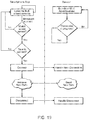
- FIG. 24 is a flow chart illustrating an exemplary process of activating a sensor device in accordance with one or more embodiments.
- Various embodiments disclosed herein are directed to methods and systems for monitoring one or more properties of building materials, including but not limited to concrete, asphalt, and epoxy.
- the methods and systems are used for monitoring one or more properties of an ambient environment (e.g., gas ambient such as air, liquid ambient).
- properties being monitored include, but are not limited to, the strength and/or relative humidity (RH) of a building structure such as a concrete structure.
- RH relative humidity
- the properties are monitored using one or more sensor devices embedded in the structure, which collect and send sensor data wirelessly to smartphones or other computer devices operated by users outside the building structure.
- Various other building material properties may also be sensed including, but not limited to, temperature, vibration, pH, gas and particle presence, load, and acoustic properties.
- the sensor system generally includes two components: a smartphone (or other computer) app and a hardware sensor device.
- the smartphone app connects to the sensor device using the Bluetooth or Bluetooth Low Energy (BLE) protocol or other wireless communications protocols such as, e.g., ANT, IEEE 802.11 and WiFi, RFID, NFC, Thread, LoRa, and ZigBee.
- BLE Bluetooth Low Energy
- the sensor device is a combination sensing device and datalogger, with a battery that lasts for a given period of time, which can vary based on intended use. By way of example, in some jobs, the battery should last for 28 days, and in other jobs it should last for two years or more.
- FIG. 1A illustrates an exemplary concrete sensor device 10 embedded in a concrete structure 12 for monitoring the strength and humidity of the structure.
- the concrete sensor device 10 is attached to rebar 14 in the structure using a cable tie 16 (also referred to as a zip tie) or other attachment mechanism.
- a cable tie 16 also referred to as a zip tie
- the sensor device 10 can also be attached to other structures within the building material including, but not limited to metal mesh, pipes, or conduits.
- FIG. 1B illustrates wireless communication between the sensor device 10 and a smartphone 18 .
- the smartphone app uses the smartphone's camera to allow the user to scan a code shown on the sensor device 10 , e.g., a QR code. Accordingly, no extra hardware such as a reader is needed to use the system. Once scanned, the app searches for a sensor device 10 broadcasting a matching identifier. When found, the app will then periodically poll the sensor device 10 for updated data.
- a code shown on the sensor device 10 e.g., a QR code. Accordingly, no extra hardware such as a reader is needed to use the system.
- the app searches for a sensor device 10 broadcasting a matching identifier. When found, the app will then periodically poll the sensor device 10 for updated data.
- the smartphone app calculates various metrics based on sensor data, including the strength of concrete (using, e.g., the methods described in ASTM C-1074).
- the app interprets the data received from sensor devices using actual mix designs while additionally providing a log of raw data content to users.
- the system utilizes a library of data on concrete mix designs in lieu of general predictions or users needing to test concrete themselves.
- FIG. 1C is an exemplary screenshot illustrating strength calculations and temperature and humidity data displayed to a user on the smartphone in graphs.
- users can share or view the graphs and displayed metrics with other devices.
- the smartphone app transmits data received from the sensor devices to a remote computer system in the cloud, which generates graphs based on the data, and transmits the graphs to the smartphone to be displayed on the smartphone or shared with other devices.
- the app can also save floor plan information, e.g., with a “pin drop” feature that allows users to set where on a floor plan a sensor device 10 is placed.
- the app can also synchronize sensor data, floor plan data, and other data with other team members.
- Sensor devices are categorized by project and subcategorized by floor. Projects can be described by a project name and project address.
- Floors are described by a floor name, concrete mix design and summary statistics of the sensor devices on that floor.
- FIGS. 1D and 1E are exemplary screenshots displayed on a user's smartphone 18 illustrating such sensor information.
- FIG. 2 is a schematic block diagram illustrating select components of a concrete sensor device 10 in accordance with one or more embodiments.
- the sensor device 10 includes a printed circuit board (PCB) assembly with an attached battery.
- the PCB assembly includes a microcontroller unit 20 , which receives temperature and humidity data from a temperature sensor 22 and a humidity sensor 24 .
- the microcontroller unit 20 also receives data from an optical sensor 26 .
- the device is powered by the battery 28 through a power regulator 30 .
- the device communicates with the smartphone app through a radio 32 . Data is stored in a non-volatile memory 34 .
- the sensor device 10 is stored in a light-blocking packaging that is removed by the installer prior to installation. When the sensor device 10 is inside a package, it retrieves an optical sensor reading every few seconds. If two consecutive readings indicate the sensor 26 is in light, it transitions to the “waiting for pour” state. In this manner, the sensor activation is not dependent on the installer providing an activation signal (e.g., flipping a mechanical switch, providing a wireless signal via an app, etc.), and hence eliminates potential user error caused by a user forgetting to activate the sensor device 10 upon installation.
- an activation signal e.g., flipping a mechanical switch, providing a wireless signal via an app, etc.
- the sensor device may include a removable streamer or tag that, when removed by the installer, activates the sensor device.
- the sensor device may include a thin filament in the zip-tie hole that is broken when a zip-tie is inserted in the hole. Breakage of the filament is detected and responsively actives the sensor device.
- the sensor device may include a pH sensor, which can determine a highly alkaline environment, indicating presence of concrete, and in response active the sensor device.
- the sensor device may include an NFC reader, allowing a smartphone to turn on the sensor device. In this case, the smartphone broadcasts an NFC signal, and the NFC reader on the sensor device listens for it to activate the device.
- FIGS. 3A-3C are illustrations of an exemplary sensor device 10 including an overmolded body 11 , according to some embodiments.
- FIG. 3A is a perspective view of the sensor device 10 including the overmolded body
- FIG. 3B is a front view of the sensor device 10 including the overmolded body
- FIG. 3C is a back view of the sensor device 10 including the overmolded body.
- the overmolded body is formed around a PCB that comprises the components forming the sensor device 10 .
- the overmolded body may be formed of plastic and/or rubber.
- the front side of the sensor device 10 includes a light guide 40 located over the optical sensor 26 within the body so as to enable light to pass through to the optical sensor 26 on the PCB.
- the sensor device 10 can also include a clear or semi-clear portion (e.g., a transparent plastic faceplate) that allows light to pass through to the optical sensor 26 .
- a cable tie 16 and cable tie opening 42 is provided so as to enable easy attachment of the sensor device 10 to construction structures, such as rebar 14 within concrete slabs. Additionally, or alternatively, one or more attachment openings 44 enable the attachment of the sensor device 10 to construction structures using any suitable attachment methods, such as metal wires, cable ties, and/or the like.
- the back side of the sensor device body (which may, e.g., be a plastic body) includes a sensor opening 46 , which enables sensing components inside the device to sense one or more properties of the building materials (e.g., temperature and/or humidity).
- the sensor opening may be provided on the front side of the sensor device 10 .
- a membrane filter 48 may be disposed in registry with the sensor opening (e.g., within the sensor opening, under the sensor opening, over the sensor opening). The membrane filter 48 allows moist vapor (e.g., moist air) into the body (where it can be sensed via the relative humidity sensor mounted on the PCB), while inhibiting or preventing liquid water, chemicals, debris, etc. from entering.
- the membrane is a polytetrafluoroethylene (PTFE) membrane, such as an extruded PTFE (ePTFE) membrane.
- PTFE polytetrafluoroethylene
- ePTFE extruded PTFE
- no membrane is used when the sensor being used requires physical contact the building material being sensed (e.g., a pH sensor).
- FIG. 4 is a flow chart illustrating an exemplary sensor device overmolding method, according to some embodiments.
- the method includes, at step 60 , forming a PCB, including forming electrical trace lines on a supporting board (e.g., metal lines, such as copper-based metal lines).
- a supporting board e.g., metal lines, such as copper-based metal lines.
- the PCB may be a single layer and/or multi-layer board, and may include traces on a front side and/or a backside.
- the method also includes assembling a plurality of components on the PCB at step 62 .
- the components include one or more of the components shown in the schematic of FIG. 2 , such as sensing components (e.g., temperature and/or humidity sensors 22 , 24 ), optical sensor 26 , microcontroller unit 20 , radio, memory, power regulator, battery, resistors, capacitors, and/or inductors.
- the method also includes mounting the membrane filter 48 over the sensing components at step 64 .
- an associated filter supporting structure is disposed over the membrane filter 48 , such that the membrane filter 48 is disposed between the sensing components and the supporting structure.
- the filter supporting structure holds the membrane filter 48 securely in place over the sensing components.
- the filter supporting structure may be a plastic structure formed via any suitable means, including, but not limited to, injection molding.
- the filter supporting structure includes an opening through which the membrane makes contact with the external environment (e.g., the building material), as shown in the perspective view of an exemplary filter supporting structure in FIG. 8 .
- the filter supporting structure is secured to the PCB using, e.g., an epoxy or a silicone applied to one or more portions or all of the filter supporting structure in contact with the PCB.
- the method further includes overmolding a body (e.g., a plastic and/or rubber body) around at least a portion or all of the PCB at step 66 .
- the overmolding may be performed utilizing, e.g., a low pressure molding process.
- the overmolding process is performed so as to ensure that the opening of the filter supporting structure is not covered with molding material.
- the overmolded body for the sensor device 10 provides seamless encapsulation of the PCB and associated components of the sensor, which ensures that during use the building material in which the sensor is placed does not enter the sensor and damage the components or interfere with the operation of the sensor.
- FIG. 5 is a perspective view of a portion of an exemplary PCB 70 on which the sensing component(s) (e.g., temperature and/or humidity sensing components 22 , 24 ) reside, according to one embodiment. It should be appreciated that the other components may be placed on one or both sides of the PCB, which is not illustrated in FIG. 5 .
- the sensing component(s) 22 , 24 may be one or more packaged components including one or more semiconductor chips and including a plurality of metal leads 76 that upon mounting on the PCB enable electrical connections to metal traces on the PCB.
- the sensing component(s) 22 , 24 backside may be placed in contact with a thermal pad on the PCB, which may be electrically connected to a ground plane of the PCB (e.g., a copper ground layer).
- the metal traces 78 electrically connected to the sensing component(s) may include a power line, a data line, a clock line, and a ground line.
- FIG. 6 is a cross-section view of an exemplary overmolded sensor device 10 , according to some embodiments.
- the membrane filter 48 is in contact with at least a portion of the sensing component(s).
- at least a portion of the top face of the sensing component(s) is disposed in contact with the membrane filter 48 .
- Such a configuration ensures that equilibrium with the external environment is attained quickly, which has been found to be especially important for relative humidity sensing.
- the presence of a substantial gap between the sensing component and the membrane filter 48 may introduce an additional delay (e.g., more than one day) in attaining sensing equilibrium with the external environment.
- a gap of less than the thickness of the membrane is provided between the membrane backside and the top face of the sensing component.
- the membrane filter 48 may have a thickness between about 0.75 mm and about 1.25 mm, and the gap thickness may be less than about 0.5 mm. In some embodiments, a gap of less than about half the thickness of the membrane filter 48 is provided between the membrane backside and the top face of the sensing component.
- the membrane filter 48 is held in contact with the sensing component(s) at least partially with a filter supporting structure. In other embodiments, the membrane filter 48 is held in contact with the sensing component without any associated supporting structure (as shown in the cross-section illustration of FIG. 6 ). To achieve such a configuration, the membrane filter 48 may be attached directly to the PCB and/or the sensing component(s), for example, utilizing an attachment material disposed around the perimeter of the membrane filter 48 and in contact with the PCB and/or sensing component(s).
- FIG. 7 is a cross-section view schematically illustrating an exemplary sensor device including a filter supporting structure 80 , according to some embodiments.
- the body of the sensor device may be an overmolded body 11 formed around a filter supporting structure 80 and leaving an opening to expose the membrane filter 48 .
- the body may be formed from the attachment of injection molded housing portions that are adhered to each other and/or the filter supporting structure. Adherence may be achieved using epoxy, heat staking, ultrasonic welding, or other suitable adherence methods.
- the filter supporting structure includes one or more shelf regions 84 that are in contact with the membrane filter 48 and hold the membrane filter 48 firmly in place over the sensing component(s) 22 , 24 .
- the filter supporting structure includes one or more legs 86 that are inserted into corresponding holes in the PCB and ensure proper place of the filter supporting structure over the sensing component(s).
- the filter supporting structure may be attached to the PCB using any suitable attachment material, for example, using an epoxy or a silicone.
- an attachment material, such as epoxy or silicone may be disposed on the legs and/or base perimeter of the filter supporting structure. Such an assembly ensures that the membrane filter 48 is in a compressive state, and hence is firmly held in place.
- FIG. 8 is a perspective view of an exemplary filter supporting structure, according to some embodiments.
- the filter supporting structure includes a shelf region around an opening 90 , which holds the membrane filter 48 firmly in place.
- the filter supporting structure includes a flange portion 92 over the shelf region(s). The flange configuration is useful for adhering the filter supporting structure to an injection molded housing, for instance, using epoxy, heat staking, ultrasonic welding, or other suitable adherence methods.
- FIG. 9 is a perspective view of an exemplary sensor device 100 having a separate sensing portion 102 electrically connected to a wireless communication portion 104 , according to some embodiments.
- the sensing portion includes the sensing component(s) mounted on a PCB board, as described for FIGS. 5-7 .
- the wireless communication portion includes at least one wireless communication component (e.g., radio component).
- the wireless communication portion also includes an optical sensor 26 , a microcontroller unit 20 , a memory, a power regulator, and a power source (e.g., a battery).
- the sensing portion includes a humidity sensor. As previously described, a membrane filter 48 is placed over the sensor. In some embodiments, the sensing portion includes one or more sensing components that sense a plurality of properties. In some embodiments, the sensing portion includes one or more sensing components that sense relative humidity and temperature.
- the separate sensing portion is connected to the wireless communication portion via an electrical cable 106 , and enables the placement of the sensing portion deep (e.g., more than about 2 feet, more than about 6 feet, or more than about 8 feet from the nearest surface of the building material structure) within a building material structure (e.g., a thick concrete slab) while the wireless communication portion is placed closer to the surface of the building material structure (e.g., less than about 1 foot, less than about 8 inches, or less than about 6 inches from the nearest surface of the building material structure).
- a building material structure e.g., a thick concrete slab
- Such a configuration enables effective transmission of a wireless communication signal out of the building material structure (e.g., a thick concrete slab), while sensing properties from portions deep within the center region of the building material structure.
- the electrical cable may include a power line, a data line, a clock line, and/or a ground line that are electrically connected to the sensing component(s) in the sensing body, which provides power and signals to operate the sensing component(s) and to send sensed data from the sensing portion to the wireless communication portion.
- the electrical cable has a length greater than about 2 feet (e.g., about 3 feet). In some embodiments, the electrical cable has a length greater than about 6 feet (e.g., about 8 feet).
- At least one of the wireless communication portion and the sensing portion includes an overmolded body, as may be formed using methods similar to that described for FIG. 4 .
- the wireless communication portion includes an overmolded body.
- the sensing portion includes an overmolded body.
- the wireless communication portion and the sensing portion include overmolded bodies.
- FIGS. 10A and 10B are top and side view illustrations, respectively, of the sensing portion, according to some embodiments.
- the sensing portion includes a sensor opening 104 , which may be formed in a manner similar to the sensor opening described in FIGS. 6-8 , and may include a membrane filter 48 and/or a filter supporting structure.
- the sensing portion includes an attachment opening 107 that enables the attachment of the sensor device 100 to construction structures using any suitable attachment methods, such as metal wires, cable ties, and/or the like.
- FIGS. 11 and 12 are top view illustrations of sensing portions including a cable tie 120 and cable tie opening 122 , according to some embodiments.
- the cable tie is substantially perpendicular to the electrical cable, as illustrated in these drawings.
- FIG. 13 is a top view illustration of a sensing portion including a cable tie and cable tie opening, according to some embodiments.
- the cable tie is substantially parallel to the electrical cable, as illustrated in the drawings.
- FIG. 14 is a perspective illustration of a sensor device including a wireless communication portion and a sensing portion in use within a building structure 130 (e.g., a concrete slab with rebar frame), according to some embodiments.
- the sensing portion may be attached to rebar 14 deep within the concrete slab
- the wireless communication portion may be attached to rebar 14 closer to a surface 132 of the concrete slab, thereby enabling effective wireless communication with an external device (e.g., a smartphone 18 ).
- an external device e.g., a smartphone 18
- FIG. 15 is a top view illustration of a sensor device including a retractable electrical cable mechanism 140 , according to some embodiments.
- the retractable electrical cable mechanism includes a spring loaded assembly (or any other suitable retraction mechanism) that retracts the electrical cable.
- a long electrical cable e.g., greater than about 6 feet
- the installer need not bother securing spare portions of the electrical cable as shown in FIG. 14 at 134 .
- FIG. 16 is a perspective illustration of a sensor device including a wireless communication portion, a sensing portion, and a retractable electrical cable mechanism in use within a building structure (e.g., a concrete slab with rebar frame), according to some embodiments.
- a building structure e.g., a concrete slab with rebar frame
- each sensor device includes multiple sensing portions 102 , each being connected to a single wireless communication portion 104 by a separate electrical cable. Each sensing portion can be embedded at a different location in the building structure.
- each sensor device 10 includes a power amplifier system to improve communication with smartphones.
- the power amplifier system can include a power and low-noise-amplifier “frontend” system to both boost the output power while also boosting the receiver gain so the device is more sensitive to incoming signals to the device.
- the sensor device 10 also includes a power saving feature to reduce power usage by the amplifier system and thereby increase battery life.
- the sensor device 10 uses certain heuristics to determine when to turn on the power amplifier system. For instance, the sensor device can broadcast some of the time using the power amplifier and some of the time without it. The device records whether incoming connections from a smartphone occurred with the amplifier on or off. If connections occur with the amplifier off, use of the amplifier is discontinued. Otherwise, the amplifier is used for subsequent communications.
- the power amplifier enables an M2M network, where a sensor device can be connected to either another sensor device (e.g., in a mesh network) or to a relay to subsequently transmit the data up to the cloud.
- the smartphone retrieves sensor data from the cloud.
- the power amplifier enables an M2M network, where a sensor device can be connected to another sensor device (e.g., in a mesh network), and the sensor devices cooperate to wirelessly communicate sensor directly to a smartphone.
- a simple quality control program is programmed onto the PCBs that runs various diagnostic procedures to ensure the sensor is assembled properly. If this program detects a failure, it flashes an LED in a specific pattern to indicate to the technician what failure was detected. If, however, no problems are detected, the LED is held in a steady state for 2 seconds before shutting off and going into lowpower “off” mode. Because the battery for the sensor is permanently attached to the sensor at this point, the quality control program should be conservative with power usage.
- the non-volatile memory in the sensor is initialized with default state information that is later used by the sensor firmware.
- the state is written as “ASSEMBLY”.
- the sensor firmware when the sensor firmware has been programmed onto the sensor, it detects if the non-volatile memory state has been initialized and is in ASSEMBLY mode. If so, the sensor shuts down for period of time so a technician can complete the packaging process. After this interval, the sensor starts up and assumes it is inside a package.
- the senor When the sensor is inside a package, it retrieves an optical sensor reading every few seconds. If two consecutive readings indicate the sensor is in light, it transitions to the “waiting for pour” state.
- the sensor When the sensor is installed while waiting for a pour, it sends a BLE advertisement about every 2 seconds.
- the sensor collects a temperature reading every 30 minutes for the first 60 days and RH reading every 24 hours.
- the sensor retrieves an optical sensor reading every 5 minutes. If consecutive readings over 18 hours indicate the sensor is in darkness, it transitions to the “encased” state. Otherwise, the sensor resets collected sample data, increment the light resets counter by 1, and continues monitoring optical data.
- the sensor When the sensor is embedded within concrete, it sends a BLE advertisement about every 2 seconds. It collects a temperature reading every 30 minutes for the first 60 days and RH reading every 24 hours. The sensor checks for the presence of light every 15 minutes. If light is detected once, the sensor clears existing data, and transitions back to the “waiting for pour” state. If no light is detected for 30 consecutive days, the sensor stops checking for light.
- the Bluetooth advertisement uses a special format for the broadcast name of the device: 05-S[12 characters], e.g., 05-Sabcdefghijkl.
- This naming format includes the sensor firmware version (“05”) as well as a delimiter (“S”). The remaining 12 characters are a unique identifier for the sensor based on the MAC address.
- QR code encodes the unique 12 character address of the device. This allows the smartphone app to correlate an image of the sensor with a BLE advertisement.
- a characteristic to print basic information about the sensor such as the protocol version.
- This service is comprised of 7 individual characteristics:
- a readable characteristic reporting the total number of temperature samples recorded by the sensor.
- a writable characteristic called a “cursor”, indicating how many samples the smartphone has previously retrieved.
- the client When the client connects, it first reads basic state and diagnostic information about the sensor, including the light resets count and the watchdog resets count.
- the client deletes all previously retrieved samples.
- the client next reads the total number of temperature samples, then the total number of RH samples. These values are used on the client side to (a) indicate to the user the progress of data retrieval, and (b) when to stop polling the sensor for sample data. 3.
- the client checks how many previously retrieved temperature and RH samples it has. It then writes these two numbers to the corresponding characteristics on the device. For instance, if the client had previously retrieved 25 temperature samples, it writes “25” to the temperature cursor characteristic. 4.
- the client then polls the sensor for temperature and RH readings. The sensor starts sending back readings at the cursor+1 and continues for each successive request until all samples have been transmitted. 5.
- the client disconnects Process of Retrieving Optical Sensor Readings 1. Retrieve 3 samples from the phototransistor 2.
- the EEPROM is divided up into three logical sections:
- the temperature and RH data are stored as 2 byte hexadecimal integers.
- the sensing chips report a floating point value of either temperature in Celsius or a percentage (RH).
- the smartphone app performs a number of functions, one of which is to organize and communicate with individual sensors. As shown in FIG. 17 , there are two ways to add a sensor: (1) A sensor can be added by scanning the QR code affixed to the front of the plastic sensor housing; and (2) A sensor can be added by searching for nearby peripherals.
- a user has removed a new sensor from its packaging and now wants to add this sensor to the smartphone app.
- the sensor turns on automatically when removed from its packaging and begins broadcasting a Bluetooth Low Energy advertisement packet (see above).
- the smartphone app turns on the built-in camera feature, which the user points at the QR code to scan.
- the QR code is a representation of the sensor's MAC address, which indicates to the smartphone app what BLE advertisement to look for. If it finds a match, the sensor is added to the smartphone app database (and sync'd). If it doesn't find a match after a period of time, it alerts the user who is unable to proceed with adding the sensor.
- the sensor is periodically broadcasting BLE advertisements except while there is an in-progress BLE connection (described in further detail below).
- Each sensor periodically broadcasts a Bluetooth advertisement packet. These packets are broadcast at approximately 2 second intervals.
- the packets are constructed using a format illustrated in FIG. 18 .
- Version indicates the sensor firmware running on this particular sensor. It allows the system to make modifications to the protocol the sensor and smartphone app will use to communicate and eliminates the need to negotiate with a round-trip Bluetooth message when first connecting.
- Delim This is a separator from the version number and MAC address. It also makes it more clear which advertising peripheral is a Concrete Sensors sensor and not some other device, reducing the likelihood of attempting to connect to some other Bluetooth peripheral that happens to be broadcasting a similarly formatted packet.
- MAC address Unique identifier, used to separate one sensor from another. Factory-determined unique number.
- the smartphone app will attempt to periodically connect to it to retrieve updated data.
- the smartphone app will not connect to a sensor if it is already engaged in synchronizing other data to/from the cloud (to prevent potential collisions with other data).
- FIG. 20 provides additional detail of how the data retrieval process works (the highlighted section in FIG. 19 ):
- the smartphone app attempts to only retrieve the data it does not already have. Further, all data is progressing forward in time: once data has been retrieved, it will never be changed and thus should not be re-downloaded.
- the smartphone app After connecting to the sensor, the smartphone app first retrieves the sensor's current light resets count number. See Handling Light Resets section below for more information.
- the smartphone app retrieves the total count of temperature samples and the total count of RH samples. These numbers are used to show a progress bar to the user and to calculate the likely date and time of a sample.
- the smartphone app determines what data it has previously retrieved (either by directly connecting to the sensor, or by synchronizing with the cloud from someone else who has directly connected to the sensor). This count is written to the sensor as the “cursor” and indicates the starting point that new data should be retrieved from. The temperature count is the first one written. 4. Finally, the smartphone app continuously requests a new packet of data until it determines there is no more data to retrieve. It then either repeats the process for RH data, or disconnects. Data Packets
- Each packet has 20 bytes in total, made up of two-byte samples in hexadecimal. Each two-byte sample is divided by 100 to find the decimal equivalent. Two examples:
- the sensor pads a buffer with NULL (or returns a buffer with only NULL). For instance, when the smartphone app finds a NULL ( FIG. 22 ), it knows there is no more data to retrieve and stops requesting more (if it was temperature, it then moves on to requesting relative humidity data; otherwise it disconnects).
- the smartphone app begins parsing it.
- the parsing process takes the data packet, splits it up into individual two-byte samples and performs the conversion process detailed above to find the decimal equivalent.
- the smartphone app also determines the date the sample was taken (detailed below).
- the smartphone app While the smartphone app is retrieving data, it is possible for a connection to be severed and data retrieval to end prematurely. If this happens, the smartphone app parses and stores the data is had retrieved and attempts to establish a new connection (where it will then write a new cursor to pick up where it left off).
- the senor does not have an onboard clock and has no concept of when a sample was taken. It can only determine relative times (e.g., 30 minutes from a previous event). As a result, the smartphone app determines the likely time of when a particular sample was taken. The accuracy of this is +/ ⁇ 30 minutes during the first 60 days of the sensor operation, and +/ ⁇ 24 hours thereafter, explained below:
- the smartphone app has never connected to a sensor before, and the sensor is still recording temperature data (which occurs every 30 minutes during the first 60 days), the smartphone app:
- the smartphone app has never connected to a sensor before, and the sensor has completed recording temperature data (but still recording RH data), the smartphone app:
- a clock may be added to the sensor. This be set by the smartphone app when adding the sensor for the first time.
- the sensor has no mechanical switch and instead uses an ambient phototransistor tuned to detect human-visible light wavelengths to determine interesting events. This phototransistor is constantly being polled to determine what state the sensor should be in.
- ASSEMBLY interim state
- the sensor When the sensor is first assembled, it is placed into an interim state (called “ASSEMBLY”). As soon as the sensor is programmed with its firmware, it transitions to the “IN_PACKAGE” state. While in this state, the sensor will periodically check for light, indicating it's been removed from its packaged and is being installed.
- the senor After being taken out of the packaging, the sensor waits for concrete to be poured around the sensor, encasing it. Whenever light is detected, the sensor all of the temperature and relative humidity data it has previously recorded, increments a light resets counter, and proceeds as FIG. 24 details.
- the smartphone app When the smartphone app connects to a sensor to retrieve data, it requests the current light resets count. If this number is greater than the light resets count for that sensor the smartphone app had previously recorded, the smartphone app deletes all of its temperature and relative humidity data and proceeds with retrieving new data from the sensor.
- a sensor will never see light while it's encased in concrete, so any time light is detected in that state, the sensor must not be concrete (and thus it resets the data it had previously collected and starts over).
- the smartphone knows when data has been reset because of this by virtue of the light resets counter having increased.
- While the exemplary embodiments disclosed herein refer to use of a smartphone in the concrete sensor system, it should be understood that various other computer devices may also be used in the system including, without limitation, personal computers, tablet computers, wearable computers (e.g., smart watches and smart glasses), personal digital assistants, and generally any computer device capable of communicating wirelessly with the sensor devices.
- the computer devices include operating systems (e.g., Android, Apple iOS, and Windows Phone OS, among others) on which applications run. The operating systems allow programmers to create applications or apps to provide particular functionality to the devices.
- a representative computer device includes at least one computer processor and a storage medium readable by the processor for storing applications and data.
- the computer device also includes input/output devices including a display for visual output, e.g., an LCD or LED display, which may have touch screen input capabilities.
Abstract
Description
3. The client checks how many previously retrieved temperature and RH samples it has. It then writes these two numbers to the corresponding characteristics on the device. For instance, if the client had previously retrieved 25 temperature samples, it writes “25” to the temperature cursor characteristic.
4. The client then polls the sensor for temperature and RH readings. The sensor starts sending back readings at the cursor+1 and continues for each successive request until all samples have been transmitted.
5. The client disconnects
Process of Retrieving Optical Sensor Readings
1. Retrieve 3 samples from the phototransistor
2. Determine variance of each sample using algorithm such as disclosed in http://en.wikipedia.org/wiki/Algorithms_for_calculating_variance#Online_algorithm
3. Remove the sample with the greatest variance
4. Average the two remaining values
5. Check if the result is greater or less than the preset darkness threshold
6. Write to the EEPROM a counter indicating how many consecutive readings of light or dark the sensor has detected.
Process of Collecting Temperature and RH Readings
1. Turn on power to the sensing chip
2. Retrieve 3 samples from the sensing chip of either temperature or RH
3. Turn off power to the sensing chip
4. Convert the raw reading from the sensing chip to a value of either Celsius or a percentage, using the formulae provided by the sensing chip manufacturer
5. Determine variance of each sample using algorithm such as disclosed in httplien.wikipedia.orewiki/Algorithms_for_calculating_variance#Online_algorithm
6. Remove the sample with the greatest variance
7. Average the two remaining values
8. Store the result onto the long term storage system (EEPROM)
Process of Storing Samples
Smartphone and Sensor Communications Overview
4. Finally, the smartphone app continuously requests a new packet of data until it determines there is no more data to retrieve. It then either repeats the process for RH data, or disconnects.
Data Packets
Claims (7)
Priority Applications (1)
| Application Number | Priority Date | Filing Date | Title |
|---|---|---|---|
| US16/459,151 US10768027B2 (en) | 2015-12-07 | 2019-07-01 | Method and system for monitoring building structures |
Applications Claiming Priority (4)
| Application Number | Priority Date | Filing Date | Title |
|---|---|---|---|
| US201562263961P | 2015-12-07 | 2015-12-07 | |
| US201662371559P | 2016-08-05 | 2016-08-05 | |
| US15/371,880 US10386210B2 (en) | 2015-12-07 | 2016-12-07 | Method and system for monitoring building structures |
| US16/459,151 US10768027B2 (en) | 2015-12-07 | 2019-07-01 | Method and system for monitoring building structures |
Related Parent Applications (1)
| Application Number | Title | Priority Date | Filing Date |
|---|---|---|---|
| US15/371,880 Division US10386210B2 (en) | 2015-12-07 | 2016-12-07 | Method and system for monitoring building structures |
Publications (2)
| Publication Number | Publication Date |
|---|---|
| US20190323865A1 US20190323865A1 (en) | 2019-10-24 |
| US10768027B2 true US10768027B2 (en) | 2020-09-08 |
Family
ID=58798374
Family Applications (2)
| Application Number | Title | Priority Date | Filing Date |
|---|---|---|---|
| US15/371,880 Active 2037-06-13 US10386210B2 (en) | 2015-12-07 | 2016-12-07 | Method and system for monitoring building structures |
| US16/459,151 Active US10768027B2 (en) | 2015-12-07 | 2019-07-01 | Method and system for monitoring building structures |
Family Applications Before (1)
| Application Number | Title | Priority Date | Filing Date |
|---|---|---|---|
| US15/371,880 Active 2037-06-13 US10386210B2 (en) | 2015-12-07 | 2016-12-07 | Method and system for monitoring building structures |
Country Status (4)
| Country | Link |
|---|---|
| US (2) | US10386210B2 (en) |
| EP (1) | EP3387417A1 (en) |
| CA (1) | CA3007471A1 (en) |
| WO (1) | WO2017100293A1 (en) |
Cited By (1)
| Publication number | Priority date | Publication date | Assignee | Title |
|---|---|---|---|---|
| US11477631B2 (en) * | 2021-03-16 | 2022-10-18 | Omidreza Ghanadiof | Earthquake damage warning system |
Families Citing this family (22)
| Publication number | Priority date | Publication date | Assignee | Title |
|---|---|---|---|---|
| CA3007471A1 (en) | 2015-12-07 | 2017-06-15 | Structural Health Systems, Inc. | Method and system for monitoring building structures |
| US11815504B2 (en) * | 2016-07-11 | 2023-11-14 | Quipip, Llc | Sensor device, and systems and methods for obtaining measurements of selected characteristics of a concrete mixture |
| WO2018035124A1 (en) | 2016-08-17 | 2018-02-22 | Quipip, Llc | Sensing device, and systems and methods for obtaining data relating to concrete mixtures and concrete structures |
| US10620062B2 (en) | 2017-10-23 | 2020-04-14 | Deborah D. L. Chung | Cement-based material systems and method for self-sensing and weighing |
| CN107995634B (en) * | 2017-11-23 | 2018-11-13 | 武汉民大信息科技有限公司 | A kind of small-scale remote local area network system and its working method based on LoRa |
| WO2019141467A1 (en) * | 2018-01-22 | 2019-07-25 | Assa Abloy Ab | Functional state transition of a sensor device based on a light signal |
| EP3743692B1 (en) * | 2018-01-22 | 2022-02-23 | Assa Abloy AB | Functional state transition of a sensor device based on proximity change of a transport protection |
| CN111656143B (en) * | 2018-01-22 | 2022-03-25 | 亚萨合莱有限公司 | Sensor device and method for switching between functional states of a sensor device |
| WO2019157041A1 (en) * | 2018-02-07 | 2019-08-15 | Gregg Novick | Smart porous concrete slab |
| CH714751A1 (en) * | 2018-03-13 | 2019-09-13 | Elpro Buchs Ag | Dataloggers in compact design. |
| US10388412B1 (en) * | 2018-03-29 | 2019-08-20 | Reciprocal Labs Corporation | Decreased latency wireless communication for use with medicament devices |
| CA3132214A1 (en) | 2019-04-03 | 2020-10-08 | Pouria Ghods | Embedded sensor devices and methods |
| SG11202111453PA (en) * | 2019-04-15 | 2021-11-29 | Concrete Data Sensors Pty Ltd | Concrete sensor device and system |
| CN110400451A (en) * | 2019-08-06 | 2019-11-01 | 江苏金恒信息科技股份有限公司 | Vibration measuring temp measuring system based on LoRa wireless communication |
| CN111354178B (en) * | 2020-03-20 | 2021-10-01 | 江苏三希科技股份有限公司 | Remote control method, system, terminal and storage medium for Lora monitoring equipment |
| CN111412952A (en) * | 2020-04-28 | 2020-07-14 | 中国东方电气集团有限公司 | Industrial environment wearable equipment |
| CA3186969A1 (en) * | 2020-07-21 | 2022-01-27 | Sai Anudeep Reddy MADDI | Thermo-piezoresistive embedded wireless sensor with real-time concrete monitoring |
| CN112584339B (en) * | 2020-12-04 | 2022-07-01 | 贵州乌江水电新能源有限公司 | Solar irradiation data acquisition node |
| SE545532C2 (en) * | 2021-04-22 | 2023-10-17 | Invisense Ab | Probe and method for collecting data on curing concrete |
| CN113310584A (en) * | 2021-04-29 | 2021-08-27 | 贵州电网有限责任公司 | Intelligent passive wireless RFID-LoRa temperature measurement method and system suitable for power equipment monitoring |
| SE545890C2 (en) * | 2021-05-28 | 2024-03-05 | Zenzr Sverige Ab | A system and method for determination of humidity of concrete |
| WO2023200366A1 (en) * | 2022-04-15 | 2023-10-19 | Общество с ограниченной ответственностью "ТЕХЗОНД" | System for determining the properties of materials |
Citations (21)
| Publication number | Priority date | Publication date | Assignee | Title |
|---|---|---|---|---|
| US4480929A (en) | 1981-08-28 | 1984-11-06 | Hansen Anker J | Method and a device for measuring concrete maturity |
| US4943930A (en) | 1986-04-18 | 1990-07-24 | Radjy Farrokh F | Method and apparatus for non-destructive evaluation of concrete |
| US5041987A (en) | 1986-11-04 | 1991-08-20 | Shimizu Construction Co., Ltd. | Method for predicting and controlling the strength development of concrete and apparatus therefor |
| US20040004554A1 (en) | 2000-12-08 | 2004-01-08 | Regaswamy Srinivasan | Wireless multi-funtional sensor platform, system containing same and method for its use |
| US20070046479A1 (en) | 2005-08-26 | 2007-03-01 | Applied Sensor Research & Development Corporation | Concrete maturity monitoring system using passive wireless surface acoustic wave temperature sensors |
| US20070116402A1 (en) | 2005-06-30 | 2007-05-24 | Infoscitex Corporation | Humidity sensor and method for monitoring moisture in concrete |
| US20070126433A1 (en) | 2005-06-03 | 2007-06-07 | Theophanis Theophanous | Permeable Moisture Sensor for Concrete, and Other Moisture Sensors, Moisture Sensing Methods and Construction Methods |
| US7551058B1 (en) | 2003-12-10 | 2009-06-23 | Advanced Design Consulting Usa, Inc. | Sensor for monitoring environmental parameters in concrete |
| US20110142091A1 (en) | 2008-05-20 | 2011-06-16 | Massachusetts Institute of Techonology | Systems and methods for structural sensing |
| US8032244B2 (en) | 2002-07-31 | 2011-10-04 | Engius, Inc. | Method and system for concrete quality control based on the concrete's maturity |
| WO2012024393A1 (en) | 2010-08-17 | 2012-02-23 | Verifi Llc | Wireless temperature sensor for concrete delivery vehicle |
| US20120173150A1 (en) | 2010-08-31 | 2012-07-05 | Francisco Romero | Sensor-based systems and methods for assessing internal bridge deck deterioration |
| US8423300B1 (en) | 2010-05-10 | 2013-04-16 | The Steel Network, Inc. | Method and system for monitoring the structural integrity of structural members of a building |
| US20130271011A1 (en) | 2009-05-21 | 2013-10-17 | Hubbell Incorporated | Occupancy sensor and override unit for photosensor-based control of load |
| WO2013188867A1 (en) | 2012-06-15 | 2013-12-19 | Smart Structures, Inc. | Pre-cast sensor assembly for monitored concrete structures |
| US20140210494A1 (en) | 2013-01-30 | 2014-07-31 | Giatec Scientific Inc. | Electrical methods and systems for concrete testing |
| US20150048844A1 (en) | 2013-08-19 | 2015-02-19 | Board Of Regents, The University Of Texas System | Corrosion detection sensor embedded within a concrete structure with a diffusion layer placed over the sacrificial transducer |
| WO2015172231A1 (en) | 2014-05-13 | 2015-11-19 | Giatec Scientific Ltd. | Electrical methods and systems for concrete testing |
| CN205537774U (en) | 2016-04-20 | 2016-08-31 | 程旭东 | Concrete structure burys formula sensor |
| CN205538970U (en) | 2016-04-11 | 2016-08-31 | 青岛理工大学 | Inside little environmental parameter normal position dynamic monitoring system of concrete |
| US10386210B2 (en) | 2015-12-07 | 2019-08-20 | Structural Health Systems, Inc. | Method and system for monitoring building structures |
-
2016
- 2016-12-07 CA CA3007471A patent/CA3007471A1/en not_active Abandoned
- 2016-12-07 WO PCT/US2016/065335 patent/WO2017100293A1/en active Application Filing
- 2016-12-07 EP EP16873747.6A patent/EP3387417A1/en not_active Withdrawn
- 2016-12-07 US US15/371,880 patent/US10386210B2/en active Active
-
2019
- 2019-07-01 US US16/459,151 patent/US10768027B2/en active Active
Patent Citations (21)
| Publication number | Priority date | Publication date | Assignee | Title |
|---|---|---|---|---|
| US4480929A (en) | 1981-08-28 | 1984-11-06 | Hansen Anker J | Method and a device for measuring concrete maturity |
| US4943930A (en) | 1986-04-18 | 1990-07-24 | Radjy Farrokh F | Method and apparatus for non-destructive evaluation of concrete |
| US5041987A (en) | 1986-11-04 | 1991-08-20 | Shimizu Construction Co., Ltd. | Method for predicting and controlling the strength development of concrete and apparatus therefor |
| US20040004554A1 (en) | 2000-12-08 | 2004-01-08 | Regaswamy Srinivasan | Wireless multi-funtional sensor platform, system containing same and method for its use |
| US8032244B2 (en) | 2002-07-31 | 2011-10-04 | Engius, Inc. | Method and system for concrete quality control based on the concrete's maturity |
| US7551058B1 (en) | 2003-12-10 | 2009-06-23 | Advanced Design Consulting Usa, Inc. | Sensor for monitoring environmental parameters in concrete |
| US20070126433A1 (en) | 2005-06-03 | 2007-06-07 | Theophanis Theophanous | Permeable Moisture Sensor for Concrete, and Other Moisture Sensors, Moisture Sensing Methods and Construction Methods |
| US20070116402A1 (en) | 2005-06-30 | 2007-05-24 | Infoscitex Corporation | Humidity sensor and method for monitoring moisture in concrete |
| US20070046479A1 (en) | 2005-08-26 | 2007-03-01 | Applied Sensor Research & Development Corporation | Concrete maturity monitoring system using passive wireless surface acoustic wave temperature sensors |
| US20110142091A1 (en) | 2008-05-20 | 2011-06-16 | Massachusetts Institute of Techonology | Systems and methods for structural sensing |
| US20130271011A1 (en) | 2009-05-21 | 2013-10-17 | Hubbell Incorporated | Occupancy sensor and override unit for photosensor-based control of load |
| US8423300B1 (en) | 2010-05-10 | 2013-04-16 | The Steel Network, Inc. | Method and system for monitoring the structural integrity of structural members of a building |
| WO2012024393A1 (en) | 2010-08-17 | 2012-02-23 | Verifi Llc | Wireless temperature sensor for concrete delivery vehicle |
| US20120173150A1 (en) | 2010-08-31 | 2012-07-05 | Francisco Romero | Sensor-based systems and methods for assessing internal bridge deck deterioration |
| WO2013188867A1 (en) | 2012-06-15 | 2013-12-19 | Smart Structures, Inc. | Pre-cast sensor assembly for monitored concrete structures |
| US20140210494A1 (en) | 2013-01-30 | 2014-07-31 | Giatec Scientific Inc. | Electrical methods and systems for concrete testing |
| US20150048844A1 (en) | 2013-08-19 | 2015-02-19 | Board Of Regents, The University Of Texas System | Corrosion detection sensor embedded within a concrete structure with a diffusion layer placed over the sacrificial transducer |
| WO2015172231A1 (en) | 2014-05-13 | 2015-11-19 | Giatec Scientific Ltd. | Electrical methods and systems for concrete testing |
| US10386210B2 (en) | 2015-12-07 | 2019-08-20 | Structural Health Systems, Inc. | Method and system for monitoring building structures |
| CN205538970U (en) | 2016-04-11 | 2016-08-31 | 青岛理工大学 | Inside little environmental parameter normal position dynamic monitoring system of concrete |
| CN205537774U (en) | 2016-04-20 | 2016-08-31 | 程旭东 | Concrete structure burys formula sensor |
Non-Patent Citations (9)
| Title |
|---|
| Command Center, accessed on Dec. 14, 2016, http://www.maturitycentral.com/. |
| ConReg, accessed on Dec. 14, 2016, http://www.controls-group.com/eng/concrete-testing-equipment/. |
| Giatec Scientific, accessed on Dec. 15, 2016, http://www.giatecscientific.com/. |
| Hard Track, accessed on Dec. 15, 2016, http://www.wakeinc.com/. |
| Heat Watch by Germann, accessed on Dec. 15, 2016, http://germann.org/products-by-application/temperature-measurement/heatwatch. |
| IntelliRock, accessed on Dec. 15, 2016, http://www.flir.com/instruments/concrete/display/?id=44885. |
| International Search Report and Written Opinion for PCT/US2016/065335, dated Mar. 24, 2017. |
| Kraft Curing, accessed on Dec. 15, 2016, http://www.kraft-systems.com/index.php/en/equipment/wireless-system. |
| Pilieci, Vito, accessed on Dec. 15, 2016, http://ottawacitizen.com/business/local-business/buried-sensors-cement-giatecs-reputation-for-concrete-solutions. |
Cited By (1)
| Publication number | Priority date | Publication date | Assignee | Title |
|---|---|---|---|---|
| US11477631B2 (en) * | 2021-03-16 | 2022-10-18 | Omidreza Ghanadiof | Earthquake damage warning system |
Also Published As
| Publication number | Publication date |
|---|---|
| EP3387417A1 (en) | 2018-10-17 |
| US20190323865A1 (en) | 2019-10-24 |
| CA3007471A1 (en) | 2017-06-15 |
| US10386210B2 (en) | 2019-08-20 |
| WO2017100293A1 (en) | 2017-06-15 |
| US20170160111A1 (en) | 2017-06-08 |
Similar Documents
| Publication | Publication Date | Title |
|---|---|---|
| US10768027B2 (en) | Method and system for monitoring building structures | |
| US11917726B2 (en) | System, method and apparatus for broadcasting sensor based event values | |
| US10575785B2 (en) | Method and apparatus for obtaining biometric information | |
| EP3343218B1 (en) | Electronic device and method for utilizing gas sensor | |
| JP5227049B2 (en) | Remote control system and remote control method | |
| US20160278014A1 (en) | Method and terminal for reporting sensor data and terminal | |
| CN104832446A (en) | Method and device for controlling fan | |
| KR101334457B1 (en) | Apparatus and method for setting auto connection of sensor node based on sensor data | |
| US11516041B2 (en) | Method and device for event notification in home network system | |
| US20140378081A1 (en) | Wireless communication system with enhanced power management | |
| KR20160120088A (en) | Electronic device and method of providing information in the electronic device | |
| US10516741B2 (en) | Control device and method for controlling function thereof | |
| JP2009243904A (en) | Data collection device | |
| CN102457558A (en) | Sensing-capacity-based terminal and application program control method | |
| ES2927034T3 (en) | Device and procedure to report the devices available in the content sharing network | |
| US9954325B2 (en) | Earphone interface and electronic device including the same | |
| US8194128B2 (en) | Surveillance device | |
| JP2012205108A (en) | System and method for radio measurement control | |
| CN108055796B (en) | Monitoring device with waterproof function | |
| KR20170054876A (en) | Method for managing schedule information and electronic device thereof | |
| CN110928797B (en) | Code coupling detection method and device, terminal equipment and storage medium | |
| US20210099837A1 (en) | Intelligent control system for monitoring computing devices and physical assets within a premises and for facilitating related transactions | |
| US20160366535A1 (en) | Field bus device for detecting an operating state of an automation device | |
| JP6301140B2 (en) | Disaster prevention monitoring equipment management system | |
| KR20200134609A (en) | MONITORING SYSTEM OF FACILITY VIBRATION ANALYSIS BASED ON IoT SENSOR AND METHOD THEREOF |
Legal Events
| Date | Code | Title | Description |
|---|---|---|---|
| FEPP | Fee payment procedure |
Free format text: ENTITY STATUS SET TO UNDISCOUNTED (ORIGINAL EVENT CODE: BIG.); ENTITY STATUS OF PATENT OWNER: LARGE ENTITY |
|
| FEPP | Fee payment procedure |
Free format text: ENTITY STATUS SET TO SMALL (ORIGINAL EVENT CODE: SMAL); ENTITY STATUS OF PATENT OWNER: LARGE ENTITY |
|
| AS | Assignment |
Owner name: STRUCTURAL HEALTH SYSTEMS, INC., MASSACHUSETTS Free format text: ASSIGNMENT OF ASSIGNORS INTEREST;ASSIGNORS:DOWDALL, BRENDAN P.;TWOMEY, RYAN P.;ARCOLEO, FRANK;AND OTHERS;SIGNING DATES FROM 20161216 TO 20161219;REEL/FRAME:050178/0779 |
|
| STPP | Information on status: patent application and granting procedure in general |
Free format text: NON FINAL ACTION MAILED |
|
| STPP | Information on status: patent application and granting procedure in general |
Free format text: NON FINAL ACTION MAILED |
|
| AS | Assignment |
Owner name: HILTI AG, LIECHTENSTEIN Free format text: ASSIGNMENT OF ASSIGNORS INTEREST;ASSIGNOR:STRUCTURAL HEALTH SYSTEMS, INC.;REEL/FRAME:052650/0526 Effective date: 20200420 |
|
| STPP | Information on status: patent application and granting procedure in general |
Free format text: NOTICE OF ALLOWANCE MAILED -- APPLICATION RECEIVED IN OFFICE OF PUBLICATIONS |
|
| FEPP | Fee payment procedure |
Free format text: ENTITY STATUS SET TO UNDISCOUNTED (ORIGINAL EVENT CODE: BIG.); ENTITY STATUS OF PATENT OWNER: LARGE ENTITY |
|
| STCF | Information on status: patent grant |
Free format text: PATENTED CASE |
|
| MAFP | Maintenance fee payment |
Free format text: PAYMENT OF MAINTENANCE FEE, 4TH YEAR, LARGE ENTITY (ORIGINAL EVENT CODE: M1551); ENTITY STATUS OF PATENT OWNER: LARGE ENTITY Year of fee payment: 4 |