US10768024B2 - Method for monitoring the thermomechanical behaviour of a subsea pipe for transporting pressurised fluids - Google Patents
Method for monitoring the thermomechanical behaviour of a subsea pipe for transporting pressurised fluids Download PDFInfo
- Publication number
- US10768024B2 US10768024B2 US16/075,053 US201716075053A US10768024B2 US 10768024 B2 US10768024 B2 US 10768024B2 US 201716075053 A US201716075053 A US 201716075053A US 10768024 B2 US10768024 B2 US 10768024B2
- Authority
- US
- United States
- Prior art keywords
- pipe element
- unit pipe
- optical fiber
- signature
- pipe
- Prior art date
- Legal status (The legal status is an assumption and is not a legal conclusion. Google has not performed a legal analysis and makes no representation as to the accuracy of the status listed.)
- Active, expires
Links
- 238000012544 monitoring process Methods 0.000 title claims abstract description 28
- 238000000034 method Methods 0.000 title claims abstract description 27
- 239000012530 fluid Substances 0.000 title claims abstract description 14
- 230000000930 thermomechanical effect Effects 0.000 title claims abstract description 7
- 239000013307 optical fiber Substances 0.000 claims abstract description 51
- 238000005259 measurement Methods 0.000 claims abstract description 42
- 239000011159 matrix material Substances 0.000 claims abstract description 15
- 238000012546 transfer Methods 0.000 claims abstract description 9
- 238000010438 heat treatment Methods 0.000 claims abstract description 8
- 238000001069 Raman spectroscopy Methods 0.000 claims description 10
- 239000000835 fiber Substances 0.000 claims description 9
- 230000003287 optical effect Effects 0.000 claims description 9
- 238000005452 bending Methods 0.000 claims description 7
- XLYOFNOQVPJJNP-UHFFFAOYSA-N water Substances O XLYOFNOQVPJJNP-UHFFFAOYSA-N 0.000 claims description 7
- 230000006835 compression Effects 0.000 claims description 5
- 238000007906 compression Methods 0.000 claims description 5
- 238000009529 body temperature measurement Methods 0.000 claims description 2
- 230000035882 stress Effects 0.000 description 39
- 238000004519 manufacturing process Methods 0.000 description 20
- 230000006870 function Effects 0.000 description 10
- 230000006399 behavior Effects 0.000 description 8
- 238000009434 installation Methods 0.000 description 7
- 229930195733 hydrocarbon Natural products 0.000 description 5
- 150000002430 hydrocarbons Chemical class 0.000 description 5
- 238000000253 optical time-domain reflectometry Methods 0.000 description 5
- 230000032258 transport Effects 0.000 description 5
- 229910000831 Steel Inorganic materials 0.000 description 4
- 230000000875 corresponding effect Effects 0.000 description 4
- 239000010959 steel Substances 0.000 description 4
- 238000012360 testing method Methods 0.000 description 4
- 238000009413 insulation Methods 0.000 description 3
- 230000000284 resting effect Effects 0.000 description 3
- 239000004215 Carbon black (E152) Substances 0.000 description 2
- 230000032683 aging Effects 0.000 description 2
- 230000015556 catabolic process Effects 0.000 description 2
- 238000006731 degradation reaction Methods 0.000 description 2
- 150000004677 hydrates Chemical class 0.000 description 2
- 239000000463 material Substances 0.000 description 2
- 238000004458 analytical method Methods 0.000 description 1
- 230000015572 biosynthetic process Effects 0.000 description 1
- 230000005494 condensation Effects 0.000 description 1
- 238000009833 condensation Methods 0.000 description 1
- 230000002596 correlated effect Effects 0.000 description 1
- 230000007423 decrease Effects 0.000 description 1
- 230000000694 effects Effects 0.000 description 1
- 239000013013 elastic material Substances 0.000 description 1
- 238000005485 electric heating Methods 0.000 description 1
- 239000004519 grease Substances 0.000 description 1
- 238000002347 injection Methods 0.000 description 1
- 239000007924 injection Substances 0.000 description 1
- 238000007689 inspection Methods 0.000 description 1
- 239000011810 insulating material Substances 0.000 description 1
- -1 oil and gas Chemical class 0.000 description 1
- 230000005693 optoelectronics Effects 0.000 description 1
- 125000006850 spacer group Chemical group 0.000 description 1
- 238000001228 spectrum Methods 0.000 description 1
- 230000008646 thermal stress Effects 0.000 description 1
- 238000013519 translation Methods 0.000 description 1
Images


Classifications
-
- G—PHYSICS
- G01—MEASURING; TESTING
- G01D—MEASURING NOT SPECIALLY ADAPTED FOR A SPECIFIC VARIABLE; ARRANGEMENTS FOR MEASURING TWO OR MORE VARIABLES NOT COVERED IN A SINGLE OTHER SUBCLASS; TARIFF METERING APPARATUS; MEASURING OR TESTING NOT OTHERWISE PROVIDED FOR
- G01D5/00—Mechanical means for transferring the output of a sensing member; Means for converting the output of a sensing member to another variable where the form or nature of the sensing member does not constrain the means for converting; Transducers not specially adapted for a specific variable
- G01D5/26—Mechanical means for transferring the output of a sensing member; Means for converting the output of a sensing member to another variable where the form or nature of the sensing member does not constrain the means for converting; Transducers not specially adapted for a specific variable characterised by optical transfer means, i.e. using infrared, visible, or ultraviolet light
- G01D5/32—Mechanical means for transferring the output of a sensing member; Means for converting the output of a sensing member to another variable where the form or nature of the sensing member does not constrain the means for converting; Transducers not specially adapted for a specific variable characterised by optical transfer means, i.e. using infrared, visible, or ultraviolet light with attenuation or whole or partial obturation of beams of light
- G01D5/34—Mechanical means for transferring the output of a sensing member; Means for converting the output of a sensing member to another variable where the form or nature of the sensing member does not constrain the means for converting; Transducers not specially adapted for a specific variable characterised by optical transfer means, i.e. using infrared, visible, or ultraviolet light with attenuation or whole or partial obturation of beams of light the beams of light being detected by photocells
- G01D5/353—Mechanical means for transferring the output of a sensing member; Means for converting the output of a sensing member to another variable where the form or nature of the sensing member does not constrain the means for converting; Transducers not specially adapted for a specific variable characterised by optical transfer means, i.e. using infrared, visible, or ultraviolet light with attenuation or whole or partial obturation of beams of light the beams of light being detected by photocells influencing the transmission properties of an optical fibre
- G01D5/35338—Mechanical means for transferring the output of a sensing member; Means for converting the output of a sensing member to another variable where the form or nature of the sensing member does not constrain the means for converting; Transducers not specially adapted for a specific variable characterised by optical transfer means, i.e. using infrared, visible, or ultraviolet light with attenuation or whole or partial obturation of beams of light the beams of light being detected by photocells influencing the transmission properties of an optical fibre using other arrangements than interferometer arrangements
- G01D5/35354—Sensor working in reflection
- G01D5/35358—Sensor working in reflection using backscattering to detect the measured quantity
- G01D5/35364—Sensor working in reflection using backscattering to detect the measured quantity using inelastic backscattering to detect the measured quantity, e.g. using Brillouin or Raman backscattering
-
- E—FIXED CONSTRUCTIONS
- E21—EARTH DRILLING; MINING
- E21B—EARTH DRILLING, e.g. DEEP DRILLING; OBTAINING OIL, GAS, WATER, SOLUBLE OR MELTABLE MATERIALS OR A SLURRY OF MINERALS FROM WELLS
- E21B17/00—Drilling rods or pipes; Flexible drill strings; Kellies; Drill collars; Sucker rods; Cables; Casings; Tubings
- E21B17/01—Risers
-
- E—FIXED CONSTRUCTIONS
- E21—EARTH DRILLING; MINING
- E21B—EARTH DRILLING, e.g. DEEP DRILLING; OBTAINING OIL, GAS, WATER, SOLUBLE OR MELTABLE MATERIALS OR A SLURRY OF MINERALS FROM WELLS
- E21B41/00—Equipment or details not covered by groups E21B15/00 - E21B40/00
- E21B41/0007—Equipment or details not covered by groups E21B15/00 - E21B40/00 for underwater installations
-
- E—FIXED CONSTRUCTIONS
- E21—EARTH DRILLING; MINING
- E21B—EARTH DRILLING, e.g. DEEP DRILLING; OBTAINING OIL, GAS, WATER, SOLUBLE OR MELTABLE MATERIALS OR A SLURRY OF MINERALS FROM WELLS
- E21B47/00—Survey of boreholes or wells
- E21B47/007—Measuring stresses in a pipe string or casing
-
- G—PHYSICS
- G01—MEASURING; TESTING
- G01D—MEASURING NOT SPECIALLY ADAPTED FOR A SPECIFIC VARIABLE; ARRANGEMENTS FOR MEASURING TWO OR MORE VARIABLES NOT COVERED IN A SINGLE OTHER SUBCLASS; TARIFF METERING APPARATUS; MEASURING OR TESTING NOT OTHERWISE PROVIDED FOR
- G01D5/00—Mechanical means for transferring the output of a sensing member; Means for converting the output of a sensing member to another variable where the form or nature of the sensing member does not constrain the means for converting; Transducers not specially adapted for a specific variable
- G01D5/26—Mechanical means for transferring the output of a sensing member; Means for converting the output of a sensing member to another variable where the form or nature of the sensing member does not constrain the means for converting; Transducers not specially adapted for a specific variable characterised by optical transfer means, i.e. using infrared, visible, or ultraviolet light
- G01D5/32—Mechanical means for transferring the output of a sensing member; Means for converting the output of a sensing member to another variable where the form or nature of the sensing member does not constrain the means for converting; Transducers not specially adapted for a specific variable characterised by optical transfer means, i.e. using infrared, visible, or ultraviolet light with attenuation or whole or partial obturation of beams of light
- G01D5/34—Mechanical means for transferring the output of a sensing member; Means for converting the output of a sensing member to another variable where the form or nature of the sensing member does not constrain the means for converting; Transducers not specially adapted for a specific variable characterised by optical transfer means, i.e. using infrared, visible, or ultraviolet light with attenuation or whole or partial obturation of beams of light the beams of light being detected by photocells
- G01D5/353—Mechanical means for transferring the output of a sensing member; Means for converting the output of a sensing member to another variable where the form or nature of the sensing member does not constrain the means for converting; Transducers not specially adapted for a specific variable characterised by optical transfer means, i.e. using infrared, visible, or ultraviolet light with attenuation or whole or partial obturation of beams of light the beams of light being detected by photocells influencing the transmission properties of an optical fibre
-
- G—PHYSICS
- G01—MEASURING; TESTING
- G01H—MEASUREMENT OF MECHANICAL VIBRATIONS OR ULTRASONIC, SONIC OR INFRASONIC WAVES
- G01H9/00—Measuring mechanical vibrations or ultrasonic, sonic or infrasonic waves by using radiation-sensitive means, e.g. optical means
- G01H9/004—Measuring mechanical vibrations or ultrasonic, sonic or infrasonic waves by using radiation-sensitive means, e.g. optical means using fibre optic sensors
-
- G—PHYSICS
- G01—MEASURING; TESTING
- G01K—MEASURING TEMPERATURE; MEASURING QUANTITY OF HEAT; THERMALLY-SENSITIVE ELEMENTS NOT OTHERWISE PROVIDED FOR
- G01K11/00—Measuring temperature based upon physical or chemical changes not covered by groups G01K3/00, G01K5/00, G01K7/00 or G01K9/00
- G01K11/32—Measuring temperature based upon physical or chemical changes not covered by groups G01K3/00, G01K5/00, G01K7/00 or G01K9/00 using changes in transmittance, scattering or luminescence in optical fibres
- G01K11/322—Measuring temperature based upon physical or chemical changes not covered by groups G01K3/00, G01K5/00, G01K7/00 or G01K9/00 using changes in transmittance, scattering or luminescence in optical fibres using Brillouin scattering
-
- G—PHYSICS
- G01—MEASURING; TESTING
- G01K—MEASURING TEMPERATURE; MEASURING QUANTITY OF HEAT; THERMALLY-SENSITIVE ELEMENTS NOT OTHERWISE PROVIDED FOR
- G01K11/00—Measuring temperature based upon physical or chemical changes not covered by groups G01K3/00, G01K5/00, G01K7/00 or G01K9/00
- G01K11/32—Measuring temperature based upon physical or chemical changes not covered by groups G01K3/00, G01K5/00, G01K7/00 or G01K9/00 using changes in transmittance, scattering or luminescence in optical fibres
- G01K11/324—Measuring temperature based upon physical or chemical changes not covered by groups G01K3/00, G01K5/00, G01K7/00 or G01K9/00 using changes in transmittance, scattering or luminescence in optical fibres using Raman scattering
-
- G01K2011/322—
-
- G01K2011/324—
-
- G—PHYSICS
- G01—MEASURING; TESTING
- G01N—INVESTIGATING OR ANALYSING MATERIALS BY DETERMINING THEIR CHEMICAL OR PHYSICAL PROPERTIES
- G01N25/00—Investigating or analyzing materials by the use of thermal means
- G01N25/18—Investigating or analyzing materials by the use of thermal means by investigating thermal conductivity
Definitions
- the present invention relates to the general field of undersea fluid transport pipes that rest on the sea bottom or that provide a bottom-to-surface connection for transporting hydrocarbons, e.g. oil and gas, from undersea production wells.
- hydrocarbons e.g. oil and gas
- Undersea fluid transport pipes are commonly used in offshore hydrocarbon production.
- a plurality of wells are generally worked, which wells may be spaced apart from one another by several kilometers, or indeed tens of kilometers.
- the fluids coming from the various wells need to be collected by pipes that are laid on the sea bottom and transferred by bottom-to-surface connection pipes from an undersea pipe resting on the sea bottom to a surface installation that receives them, e.g. on board a ship or at a collection point situated onshore.
- the invention relates more particularly to coaxial pipes of the pipe in pipe (PIP) type, in which an inner steel tube transports the fluids and an outer steel tube coaxial with the internal tube, and also referred to as the “outer shell”, is in contact with the surrounding medium, i.e. with the water.
- PIP pipe in pipe
- such coaxial pipes are assembled on land from unit lengths (referred to as double, triple, or quadruple “joints”, with the term “quad-joints” being used herein for quadruple sections of tube), which unit lengths present a length lying in the range 10 meters (m) to 100 m, depending on the load-holding capacity of the laying system.
- quad-joints are then taken to sea on a laying ship.
- the quad-joints are connected to one another on board the ship progressively as they are being laid at sea.
- This laying may be performed by using a J-lay tower positioned on the laying ship.
- the undersea pipe is typically lowered from the laying ship while it is practically vertical (at an angle in the range +30° to ⁇ 10° relative to the vertical).
- J-laying is single-catenary laying in which the almost vertical angle of inclination of the pipe decreases progressively as it moves downwards until it takes on the slope of the sea bottom.
- undersea fluid transport pipes are designed to achieve a high level of thermal performance, and specific versions have been developed to be better adapted to great depths, i.e. to withstand pressure at the bottom of the sea.
- the pressure of water is substantially 0.1 megapascals (MPa), i.e. about 1 bar, for a depth of 10 m
- the pressure that undersea pipes need to be able to withstand is then about 10 MPa, i.e. about 100 bar, for a depth of 1000 m, and about 30 MPa, i.e. about 300 bar, for a depth of 3000 m.
- undersea pipes are subjected to high levels of mechanical stress, both while they are being laid on the bottom of the sea via a J-lay tower, which gives rise to high levels of deformation (in particular in bending) in each of the quad-joints of the pipe, and also during the production stage (internal thermal stresses and stresses due to external forces).
- the inner tubes of the quad-joints of the pipe are subjected to the high pressure of the fluids they are transporting (which pressure can exceed 100 bar).
- the sea bottom on which the pipe is resting moves, which gives rise to movements of the pipe, and thus to stresses in them.
- thermomechanical integrity of an undersea pipe for transporting fluids, both while it is being laid and also during a stage of production.
- thermomechanical behavior of an undersea pipe for transporting fluid under pressure the undersea pipe being made by assembling together a plurality of unit pipe elements arranged end to end, the method comprising:
- a step of determining a mechanical signature specific to each unit pipe element which step consists in using at least one measurement cable having at least one optical fiber sensor using at least Brillouin backscattering and positioned along the entire length of the unit pipe element to measure the deformations experienced by or simulated on said unit pipe element while it is being subjected on land to various different mechanical stresses in predetermined directions and of predetermined magnitudes, and, on the basis of the deformation measurements, in establishing a stiffness matrix associated with the mechanical signature of the unit pipe element;
- a step of determining a thermal signature specific to each unit pipe element which step consists in using at least one measurement cable provided with at least one optical fiber sensor using at least Raman backscattering and positioned along the entire length of the unit pipe element to measure temperature changes of said unit pipe element while it is being subjected on land to various different electrical heating powers, and, on the basis of these temperature measurements, in establishing a thermal transfer function associated with the thermal signature of the unit pipe element;
- a monitoring step consisting in recovering the variations in the optical signal injected into the optical fiber sensors while the pipe is in service, and on the basis of these variations in the optical signal, in determining any changes in the mechanical and thermal signatures of each unit pipe element.
- a pipe is said to be “in service” either while the pipe is being laid, or else while it is operational during a stage of production from the network.
- the monitoring method of the invention is remarkable in that it makes use of mechanical and thermal signatures that are specific to each unit element (or quad-joint) of the undersea pipe for monitoring the temperature and the mechanical stresses to which the pipe is subjected.
- each unit pipe element Prior to being laid, during the step of determining a mechanical signature, each unit pipe element is tested on land (in a laboratory or a factory) and it is subjected to various different mechanical stresses of predetermined directions and magnitudes.
- the deformations experienced by or simulated on the unit pipe element are measured by optical fiber sensors (each optical fiber sensor is associated with measuring one deformation parameter of the unit pipe element).
- the measurements taken by the optical fiber sensors are used to determine changes in the mechanical signatures specific to each unit pipe element, and thus to track the deformations to which each of the unit pipe elements are subjected in service.
- the mechanical signatures of each of the unit pipe elements constitute references that make it possible to locate events throughout the lifetime of the pipe.
- the method of the invention is also most particularly suitable for the J-laying technique for laying an undersea pipe, during which no permanent deformation is imparted to the pipe (the pipe remains below 90% of its elastic limit). Once it has been laid, the pipe continues to remain in a linear domain (below 66% of its elastic limit), which means that the disturbing phenomena experienced by the pipe (such as deformations) can be linearized.
- each unit pipe element is subjected to various different heating powers. Changes in the temperature of the unit pipe element are measured by the optical fiber sensor using Raman backscattering. These temperature changes, which are specific to each unit pipe element, make it possible to determine thermal transfer functions having values that correspond to the temperature rise values experienced by the unit pipe element. During the monitoring step proper, the measurements performed by the optical fiber sensor using Raman backscattering are used to determine any changes in the thermal signature specific to each unit pipe element, and thus to track the temperatures seen in service by each of the unit pipe elements. Knowledge of changes in the thermal signature of each unit pipe element serves in particular to monitor the operation of the electric heater cables and to observe ageing of the insulation and the appearance of layers of hydrates in the pipe.
- the monitoring method of the invention also makes it possible to have accurate knowledge about the state of the undersea pipe at the connections between the various unit pipe elements, which is not possible with a single measurement line over the entire length of the pipe.
- the stiffness matrix associated with the mechanical signature of each unit pipe element may comprise values corresponding to the values of deformations experienced by the unit pipe element while it was being subjected on land to various different mechanical stresses.
- the stiffness matrix that is set up using these measurements represents the mechanical identity specific to each unit pipe element. Under such circumstances, determining the deformations experienced by each unit pipe element in service makes it possible to calculate the stiffness matrix associated with the mechanical signature of each unit pipe element.
- the thermal transfer function associated with the thermal signature of each unit pipe element may comprise values corresponding to the values of the temperature rises experienced by the unit pipe element while being subjected on land to various different heating powers. Under such circumstances, the temperature seen in service by each of the unit pipe elements makes it possible to calculate the thermal transfer functions.
- the mechanical stresses of predetermined directions and amplitudes applied on land to each unit pipe element may comprise one or more of the following stresses: twisting stress; traction/compression stress; bending stress; and pressure stress.
- the optical fiber sensor measurement cables may be positioned on the unit pipe elements in such a manner as to extend substantially parallel to a longitudinal axis of said pipe.
- the measurement cable optical fiber sensors that use Brillouin and Rayleigh backscattering are monomode fibers and the measurement cable optical fiber sensors that use Raman backscattering are multimode fibers.
- each unit pipe element may comprise an inner tube mounted coaxially inside an outer tube, the optical fiber sensor measurement cables being positioned on the inner tube of said unit pipe element.
- the method further comprises:
- a step of determining an acoustic and vibratory signature specific to each unit pipe element consisting in using the measurement cable having the optical fiber sensor that uses at least Rayleigh backscattering and that is positioned along the entire length of the unit pipe element to measure the frequency variations of each unit pipe element while it is being subjected on land to various different acoustic and vibratory stresses, and on the basis of these noise variations, to establish an acoustic signature for each unit pipe element;
- a step of monitoring the acoustic and vibratory integrity of the pipe which step consists in recovering the frequency variations of the optical signal injected into the optical fiber sensors while the pipe is in service, and on the basis of the frequency variations, in determining any changes in the acoustic and vibratory signature of each unit pipe element.
- the optical fiber sensors that use Brillouin backscattering can not only provide information about the mechanical stresses experienced by the pipe, but can also provide information about variations in surrounding sources of vibration.
- surrounding sources of vibration it is possible in particular to distinguish between those generated by the unit pipe element on which the optical fiber sensors are positioned, and those generated by the outside environment (specifically the sea bottom and anything connected thereto).
- the integrity of the pipe may be monitored on the basis of changes in the acoustic and vibratory signatures of each of the unit pipe elements.
- the noise variations detected inside the pipe make it possible to determine the proportions of the flowing fluid phases and their respective speeds.
- Continuous noise variations can make it possible to detect heavy grease forming on the walls of the pipe, which reduces flow and locally increases the speed of the fluid.
- Noise variations can also be symptomatic of the pipe moving (by expanding laterally or vertically) potentially giving rise to (fatigue) damage of the pipe.
- Noise variations outside of the undersea pipe are useful in particular during an external programmed intervention on the pipe (e.g. inspection by means of a remotely controlled undersea vehicle). Specifically, during such interventions, recognizing noise variations makes it possible to determine to within 1 m the position of the controlled vehicle relative to the undersea pipe, thereby enabling the vehicle to be guided better and enabling its external view to be correlated with the acoustic view internal to the pipe. Other outside noises can be evaluated and extracted from analyses of the behavior of the pipe since they correspond to known natural physical phenomena such as landslides or tsunamis that can be heard from far away and that are not likely to damage the pipe.
- the acoustic and vibratory stresses applied on land to each unit pipe element may comprise: emitting noises inside of the unit pipe element filled with air via a bar connecting together the two ends of said unit pipe element, emitting noises inside of the unit pipe element filled with water via a bar connecting together the two ends of said unit pipe element, and setting the entire unit pipe element into vibration by means of vibrating studs.
- FIG. 1 is a diagrammatic view of an undersea PIP pipe to which it is possible to apply the monitoring method of the invention
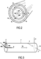
- FIG. 2 is a section view on II-II of FIG. 1 ;
- FIG. 3 is a diagrammatic view of a unit undersea pipe element to which various different mechanical stresses are applied in order to establish its mechanical signature.
- the invention applies to any undersea pipe resting on the sea bottom and serving to transport specifically oil and gas between undersea hydrocarbon production wells and a surface installation, such as the undersea pipe 2 shown in FIGS. 1 and 2 .
- the undersea pipe 2 shown in the figures is typically assembled on land as a plurality of pipe sections 4 each having a unit length of about 10 m to 100 m, depending on the load-holding capacity of the laying system.
- the term “joints” is also used, in particular “double joints” for two unit pipe elements assembled together, “triple joints” for three unit pipe elements assembled together, “quadruple joints” for four unit pipe elements assembled together, etc.
- quad-joint is used generically to designate any unit pipe element 4 . During laying, the quad-joints 4 are connected to one another on board the ship progressively as they are being laid at sea.
- each quad-joint (or unit pipe element) 4 comprises an inner steel tube 6 for transporting hydrocarbons from production wells, and an outer steel tube 8 that is coaxial about the inner tube and that is referred to as the “outer shell”, which outer tube is in direct contact with the surrounding water.
- the annular space 10 formed between the inner tube 6 and the outer tube 8 of each quad-joint 4 may be filled with an insulating material 12 (or may have gas evacuated therefrom) so as to form a thermally insulating layer that limits the loss of heat to the surrounding medium.
- the inner tube 6 may be secured to the outer tube 8 via junction parts 14 that close the annular space 10 .
- thermomechanical integrity of such an undersea pipe 2 i.e. to monitor variation in mechanical and thermal signatures of each of the unit pipe elements making it up, both during laying on the sea bottom and also during production by the network (i.e. while it is in service).
- the monitoring method of the invention provides for two main steps: steps referred to as “initial measurement” (or calibration) steps, during which the initial mechanical signature, the initial thermal signature, and the initial acoustic and vibratory signature of each quad-joint of the undersea pipe are determined; and a monitoring step proper during which variations in the mechanical, thermal, and acoustic and vibratory signatures are determined on the basis of thermomechanical stresses applied to each quad-joint and on the basis of measurements taken by optical fiber sensors while the undersea pipe is being laid and/or during production from the network.
- steps referred to as “initial measurement” (or calibration) steps during which the initial mechanical signature, the initial thermal signature, and the initial acoustic and vibratory signature of each quad-joint of the undersea pipe are determined
- a monitoring step proper during which variations in the mechanical, thermal, and acoustic and vibratory signatures are determined on the basis of thermomechanical stresses applied to each quad-joint and on the basis of measurements taken by optical
- This mechanical calibration step consists in testing each quad-joint of the undersea pipe on land in order to obtain its initial mechanical signature.
- each quad-joint is subjected in a laboratory or a factory to a series of various different mechanical stresses in predetermined directions and of predetermined magnitudes, and the deformations experienced by the quad-joint during the testing are measured by optical fiber sensors.
- the quad-joint 4 is fitted with measurement cables 16 provided with optical fiber sensors, each optical fiber sensor being for measuring a single corresponding deformation parameter of the quad-joint.
- the measurement cables 16 are to be positioned on the inner tube 6 of the quad-joint 4 (by way of example, they may be adhesively bonded to its outside surface) and they are to extend longitudinally between the two ends of the quad-joint.
- the optical fibers in the measurement cables 16 are monomode fibers making use of Brillouin and Rayleigh backscattering for sensors that are to measure the mechanical stresses to which the quad-joint is subjected and the variations in acoustic and vibratory noise, and a multimode fiber using Raman backscattering for the sensor that is to measure the temperature of the quad-joint (during the thermal calibration step, described below).
- the mechanical stresses applied to the quad-joints of the undersea pipe are the following: twisting stress (about the longitudinal axis 18 of the quad-joints); bending stress (in a YZ plane transverse to the quad-joints); traction/compression stress (along the direction of the longitudinal axis of the quad-joints); and pressure stress internal to the quad-joints.
- the twisting stress applied to the quad-joint 4 consists in creating a twisting moment (represented by Mtx in FIG. 3 ) having as its application direction the X axis of an (0, X, Y, Z) rectangular reference frame specific to the quad-joint.
- the bending stress applied to the quad-joint consists in creating two bending moments (represented by Mfy and Mfz in FIG. 3 ) having respective application directions along the Y and Z axes of the (0, X, Y, Z) reference frame.
- the traction/compression stress applied to the quad-joint (shown in FIG. 3 by Nx) has an application direction along the X axis.
- the pressure stress is represented by P in FIG. 3 and its application direction is radial relative to the pipe.
- an optoelectronic measurement apparatus of the optical time domain reflectometer (OTDR) type serves to measure the deformation values, written ⁇ i , to which the quad-joint is subjected.
- each optical fiber sensor measures a single deformation value ⁇ i , such that in order to obtain all of the deformation values of the quad-joint corresponding to the above-described stresses Mtx, Mfy, Mfz, Nx, and P, it is necessary to have five different optical fiber sensors for a single quad-joint.
- This stiffness matrix ⁇ constitutes a mechanical signature that is specific to each quad-joint for making up the undersea pipe. Specifically, the parameters and the tolerances of the component materials (concentricity and thicknesses of the tubes, stiffnesses of the insulation in the annulus and of the spacers, characteristics of welded joints, etc.) are different for each quad-joint, such that the stiffness matrix varies from one quad-joint to another.
- the mechanical signatures are in the form of digital files that are stored in a memory of a computer system on board the laying ship and/or the surface installation, for subsequent use in monitoring the mechanical behavior of the undersea pipe during the monitoring step proper, as described below.
- each quad-joint of the undersea pipe is fitted with at least one measurement cable provided with at least one optical fiber sensor using at least Raman backscattering.
- the optical fiber sensor typically a multimode sensor, is more precisely inserted inside one of the measurement cables 16 fitted to each quad-joint.
- Each quad-joint fitted in this way is then subjected to various different levels of electric heating power while on land (i.e. in a laboratory or a factory).
- the temperature variations of each quad-joint subjected to such heating powers are measured by an optical time domain reflectometer (OTDR) used for characterizing the optical fiber sensors that make use of Raman backscattering.
- OTDR optical time domain reflectometer
- T(t) represents the variation in the temperature of the inner tube of each quad-joint measured by the optical fiber sensor
- P electrical corresponds to the electrical power injected into the heater system.
- the values of the thermal transfer functions a(t) and b(t) correspond to the temperature rise values experienced by the inner tube of the quad-joint when it is subjected to various different heating powers on land.
- the thermal signatures of the quad-joint are in the form of digital files that are stored in a memory of the computer system on board the laying ship and/or the surface installation, for subsequent use in monitoring the mechanical behavior of the undersea pipe during the monitoring step proper.
- This acoustic calibration step takes place under the same operating conditions as the mechanical calibration stage.
- Each quad-joint fitted with its optical fiber sensor using Brillouin backscattering is subjected to various different acoustic and vibratory stresses on land (i.e. in a laboratory or in a factory).
- These acoustic stresses comprise emitting noises (in a working frequency spectrum typically ranging from 0 to 50 kHz) in various configurations: emitting noises inside the quad-joint filled with air via a bar connecting together the two ends of the quad-joint; emitting noises into the inside of the quad-joint filled with water via a bar connecting together its two ends; and by emitting noises outside the quad-joint previously filled with air and then with water by using a protocol that is calibrated for each quad-joint (e.g. by means of a system that emits calibrated sound vibration).
- the vibratory stresses may be provided by setting the entire unit pipe element into vibration by means of vibrating studs.
- the optical time domain reflectometer that is used for characterizing the optical fiber sensors also serves to measure the frequency variations of the quad-joint.
- these measurements are in the form of a matrix and constitute the acoustic and vibratory signature for each quad-joint (i.e. its base reference).
- the acoustic signatures of all of the quad-joints are in the form of digital files that are stored in a memory of the computer system on board the laying ship and/or the surface installation, for subsequent use in monitoring the behavior of the undersea pipe during the monitoring step proper, as described below.
- the various quad-joints 4 that are to make up the undersea pipe 2 are connected to one another on board the ship progressively while they are being laid at sea, as is known to the person skilled in the art.
- the quad-joints 4 are indexed in rotation relative to one another, i.e. the (0, X, Y, Z) reference frame specific to each quad-joint is identified both in rotation and in translation in a more general reference frame by means of a geographical information system (GIS).
- GIS geographical information system
- the measurements taken by optical time domain reflectometry (OTDR) of the optical fiber sensors using Brillouin backscattering are analyzed in order to determine the behavior of the undersea pipe faced with the deformation to which it might be subjected.
- This step of recovering and analyzing measurements taken by optical time domain reflectometry may be performed by the computer system provided with suitable software means and present on board the laying ship and/or the surface installation.
- the thermal signatures of the undersea pipe are monitored on the basis of thermal variations to which the pipe is subjected.
- Monitoring of the acoustic and vibratory signatures of the undersea pipe is performed by comparing the measurements taken throughout the stage of production in the network by optical time domain reflectometry (OTDR) of the optical fiber sensors using Brillouin backscattering with the acoustic and vibratory signatures established for each quad-joint during the acoustic calibration step.
- OTDR optical time domain reflectometry
- This step of recovering and analyzing measurements taken by optical time domain reflectometry may be performed by the computer system provided with suitable software means and present on board the laying ship and/or the surface installation.
- each quad-joint may also be used for monitoring the fabrication quality of the quad-joints by verifying that the parameters of the stiffness matrix and the thermal backscattering functions of each quad-joint remain within a predefined range of values.
Applications Claiming Priority (3)
| Application Number | Priority Date | Filing Date | Title |
|---|---|---|---|
| FR1650826 | 2016-02-02 | ||
| FR1650826A FR3047308B1 (fr) | 2016-02-02 | 2016-02-02 | Procede de surveillance du comportement thermomecanique d'une conduite sous-marine de transport de fluides sous pression |
| PCT/FR2017/050120 WO2017134360A1 (fr) | 2016-02-02 | 2017-01-20 | Procédé de surveillance du comportement thermomécanique d'une conduite sous-marine de transport de fluides sous pression |
Publications (2)
| Publication Number | Publication Date |
|---|---|
| US20190033102A1 US20190033102A1 (en) | 2019-01-31 |
| US10768024B2 true US10768024B2 (en) | 2020-09-08 |
Family
ID=55590066
Family Applications (1)
| Application Number | Title | Priority Date | Filing Date |
|---|---|---|---|
| US16/075,053 Active 2037-10-06 US10768024B2 (en) | 2016-02-02 | 2017-01-20 | Method for monitoring the thermomechanical behaviour of a subsea pipe for transporting pressurised fluids |
Country Status (5)
| Country | Link |
|---|---|
| US (1) | US10768024B2 (fr) |
| EP (1) | EP3411668B1 (fr) |
| BR (1) | BR112018015392B1 (fr) |
| FR (1) | FR3047308B1 (fr) |
| WO (1) | WO2017134360A1 (fr) |
Families Citing this family (7)
| Publication number | Priority date | Publication date | Assignee | Title |
|---|---|---|---|---|
| FR3047309B1 (fr) * | 2016-02-02 | 2019-07-26 | Saipem S.A. | Procede et dispositif de surveillance du comportement mecanique d'une conduite sous-marine de transport de fluides sous pression |
| FR3070499B1 (fr) | 2017-08-31 | 2019-09-06 | Saipem S.A. | Procede de determination des variations de contraintes au cours du temps d'une conduite sous-marine de transport de fluides |
| WO2020027223A1 (fr) * | 2018-07-31 | 2020-02-06 | 古河電気工業株式会社 | Câble, système de détection de forme de câble, système de détection et procédé de détection de forme de câble |
| US11795783B2 (en) * | 2019-05-24 | 2023-10-24 | ExxonMobil Technology and Engineering Company | Method and system for acoustic monitoring and pattern recognition in hydrocarbon management activities |
| CN111753392A (zh) * | 2020-05-18 | 2020-10-09 | 缤谷电力科技(上海)有限公司 | 一种含有局部热点的gis振动特性试验系统及方法 |
| CN115077692B (zh) * | 2022-08-22 | 2022-12-06 | 山东一唯自动化有限公司 | 一种流体振动检测装置 |
| CN117433587B (zh) * | 2023-12-14 | 2024-03-19 | 江苏南方通信科技有限公司 | 对称结构多参数弱光栅传感光缆、传感系统和测量方法 |
Citations (11)
| Publication number | Priority date | Publication date | Assignee | Title |
|---|---|---|---|---|
| US20030174924A1 (en) * | 2002-03-14 | 2003-09-18 | Tennyson Roderick C. | Monitoring of large structures using brillouin spectrum analysis |
| CN101713638A (zh) | 2009-12-22 | 2010-05-26 | 浙江大学 | 埋入式长距离光纤传感器的标定方法及装置 |
| US20110007996A1 (en) * | 2009-07-07 | 2011-01-13 | At&T Intellectual Property I, L.P. | Optical Fiber Pipeline Monitoring System and Method Field |
| CN102636730A (zh) | 2012-02-22 | 2012-08-15 | 上海海事大学 | 复合海缆温升应变监测告警及故障分析方法 |
| US20150308909A1 (en) * | 2014-04-24 | 2015-10-29 | Ge-Hitachi Nuclear Energy Americas Llc | Fiber optic pipeline acoustic measurement method, device, and system |
| CA2910468A1 (fr) | 2014-07-22 | 2016-01-22 | Huaizhi SU | Dispositif et methode de test, dynamique et statique, multi-objectif multi-degre de liberte de fibre optique a detection distribuee |
| US20160169807A1 (en) * | 2013-09-24 | 2016-06-16 | Fujitsu Limited | Optical fiber cord and abnormality detection system |
| US20160202133A1 (en) * | 2013-03-13 | 2016-07-14 | University de Nantes | Strain measuring device |
| US20170167949A1 (en) * | 2014-06-16 | 2017-06-15 | Halliburton Energy Services, Inc. | Distributed nondestructive inspection system and method for identifying slickline cable defects and mechanical strength degradation trend |
| US20170260848A1 (en) * | 2015-03-10 | 2017-09-14 | Halliburton Energy Services, Inc | A Wellbore Monitoring System Using Strain Sensitive Optical Fiber Cable Package |
| US20180087999A1 (en) * | 2016-09-26 | 2018-03-29 | Commissariat A L'energie Atomique Et Aux Energies Alternatives | Instrumented concrete structural element |
Family Cites Families (3)
| Publication number | Priority date | Publication date | Assignee | Title |
|---|---|---|---|---|
| US20050283276A1 (en) * | 2004-05-28 | 2005-12-22 | Prescott Clifford N | Real time subsea monitoring and control system for pipelines |
| US20110090496A1 (en) * | 2009-10-21 | 2011-04-21 | Halliburton Energy Services, Inc. | Downhole monitoring with distributed optical density, temperature and/or strain sensing |
| MY172737A (en) * | 2009-10-23 | 2019-12-11 | Sensortran Inc | Stimulated brillouin system with multiple fbg's |
-
2016
- 2016-02-02 FR FR1650826A patent/FR3047308B1/fr not_active Expired - Fee Related
-
2017
- 2017-01-20 US US16/075,053 patent/US10768024B2/en active Active
- 2017-01-20 EP EP17706552.1A patent/EP3411668B1/fr active Active
- 2017-01-20 WO PCT/FR2017/050120 patent/WO2017134360A1/fr active Application Filing
- 2017-01-20 BR BR112018015392-3A patent/BR112018015392B1/pt active IP Right Grant
Patent Citations (11)
| Publication number | Priority date | Publication date | Assignee | Title |
|---|---|---|---|---|
| US20030174924A1 (en) * | 2002-03-14 | 2003-09-18 | Tennyson Roderick C. | Monitoring of large structures using brillouin spectrum analysis |
| US20110007996A1 (en) * | 2009-07-07 | 2011-01-13 | At&T Intellectual Property I, L.P. | Optical Fiber Pipeline Monitoring System and Method Field |
| CN101713638A (zh) | 2009-12-22 | 2010-05-26 | 浙江大学 | 埋入式长距离光纤传感器的标定方法及装置 |
| CN102636730A (zh) | 2012-02-22 | 2012-08-15 | 上海海事大学 | 复合海缆温升应变监测告警及故障分析方法 |
| US20160202133A1 (en) * | 2013-03-13 | 2016-07-14 | University de Nantes | Strain measuring device |
| US20160169807A1 (en) * | 2013-09-24 | 2016-06-16 | Fujitsu Limited | Optical fiber cord and abnormality detection system |
| US20150308909A1 (en) * | 2014-04-24 | 2015-10-29 | Ge-Hitachi Nuclear Energy Americas Llc | Fiber optic pipeline acoustic measurement method, device, and system |
| US20170167949A1 (en) * | 2014-06-16 | 2017-06-15 | Halliburton Energy Services, Inc. | Distributed nondestructive inspection system and method for identifying slickline cable defects and mechanical strength degradation trend |
| CA2910468A1 (fr) | 2014-07-22 | 2016-01-22 | Huaizhi SU | Dispositif et methode de test, dynamique et statique, multi-objectif multi-degre de liberte de fibre optique a detection distribuee |
| US20170260848A1 (en) * | 2015-03-10 | 2017-09-14 | Halliburton Energy Services, Inc | A Wellbore Monitoring System Using Strain Sensitive Optical Fiber Cable Package |
| US20180087999A1 (en) * | 2016-09-26 | 2018-03-29 | Commissariat A L'energie Atomique Et Aux Energies Alternatives | Instrumented concrete structural element |
Non-Patent Citations (1)
| Title |
|---|
| Alahbabi, Mohamed N., Yuh Tat Cho, and Trevor P. Newson. "Long-range distributed temperature and strain optical fibre sensor based on the coherent detection of spontaneous Brillouin scattering with in-line Raman amplification." Measurement Science and Technology 17.5 (2006): 1082. (Year: 2006). * |
Also Published As
| Publication number | Publication date |
|---|---|
| US20190033102A1 (en) | 2019-01-31 |
| FR3047308A1 (fr) | 2017-08-04 |
| EP3411668A1 (fr) | 2018-12-12 |
| BR112018015392A2 (pt) | 2018-12-18 |
| FR3047308B1 (fr) | 2018-02-16 |
| EP3411668B1 (fr) | 2020-03-04 |
| BR112018015392B1 (pt) | 2022-11-16 |
| WO2017134360A1 (fr) | 2017-08-10 |
Similar Documents
| Publication | Publication Date | Title |
|---|---|---|
| US10768024B2 (en) | Method for monitoring the thermomechanical behaviour of a subsea pipe for transporting pressurised fluids | |
| US10488296B2 (en) | Method of determining stress variations over time in an undersea pipe for transporting fluids | |
| US9341054B2 (en) | System for monitoring linearity of down-hole pumping systems during deployment and related methods | |
| US8520195B2 (en) | Method and system for estimating fluid leak flow rates using distributed optical fiber sensors | |
| ES2637023T3 (es) | Sistema y método para monitorizar un pozo | |
| US10768023B2 (en) | Method and device for monitoring the mechanical behaviour of a subsea pipe for transporting pressurized fluids | |
| EP2705342B1 (fr) | Surveillance de l'intégrité de conduits | |
| EP2065551A2 (fr) | Tuyau flexible | |
| WO2009158630A1 (fr) | Procédé et système pour estimer des débits de fuite de fluide à l'aide de capteurs à fibre optique distribués | |
| CN112268642A (zh) | 基于分布式光纤传感的地下应力测量装置及测量方法 | |
| Xu et al. | Surface crack detection in Prestressed concrete cylinder pipes using BOTDA strain sensors | |
| Wong et al. | Utilising hydraulic transient excitation for fatigue crack monitoring of a cast iron pipeline using optical distributed sensing | |
| AU2016229467A1 (en) | Distributed strain monitoring for downhole tools | |
| US10031043B2 (en) | Method and apparatus for detecting a structural fault in a structure using a brillouin gain spectrum obtained at a point along a sensing optical fiber | |
| Inaudi et al. | Fiber optic sensing for innovative oil & gas production and transport systems | |
| Liu et al. | Pipeline safety monitoring technology based on FBG-ROTDR joint system and its case study of urban drainage pipeline monitoring | |
| WO2023024364A1 (fr) | Système de mesure de pression de fluide souterrain basé sur une fibre optique de réseau continue, et procédé de mesure | |
| CN114152371A (zh) | 基于分布式螺旋状铠装光缆的地下应力场测量装置及方法 | |
| OA18858A (en) | Procédé de surveillance du comportement thermomécanique d'une conduite sous-marine de transport de fluides sous pression | |
| Li* et al. | Laboratory evaluation of a real-time coaxial cable casing imager for wellbore integrity monitoring | |
| Lim | Novel applications of distributed fiber optic sensors for pipeline structural health monitoring | |
| Li et al. | Robust and Cost Effective Distributed Coaxial Cable Sensors Verified As Real-Time Permanent Downhole Monitoring for Groundwater Safety in Geological CO2 Storage | |
| Sham | Spatial deformation estimation and long term structural health monitoring in underground engineering | |
| Servette et al. | Optical fiber sensors for subsea and topside asset integrity monitoring applications | |
| Zhuang et al. | Utilising Hydraulic Transient Excitations for SHM of pipeline with Distributed Optical Fibre Sensing |
Legal Events
| Date | Code | Title | Description |
|---|---|---|---|
| FEPP | Fee payment procedure |
Free format text: ENTITY STATUS SET TO UNDISCOUNTED (ORIGINAL EVENT CODE: BIG.); ENTITY STATUS OF PATENT OWNER: LARGE ENTITY |
|
| AS | Assignment |
Owner name: SAIPEM S.A., FRANCE Free format text: ASSIGNMENT OF ASSIGNORS INTEREST;ASSIGNORS:PIONETTI, FRANCOIS-REGIS;AGOUMI, JALIL;SUNDERMANN, AXEL;AND OTHERS;SIGNING DATES FROM 20180821 TO 20180928;REEL/FRAME:047337/0404 Owner name: CEMENTYS, FRANCE Free format text: ASSIGNMENT OF ASSIGNORS INTEREST;ASSIGNORS:PIONETTI, FRANCOIS-REGIS;AGOUMI, JALIL;SUNDERMANN, AXEL;AND OTHERS;SIGNING DATES FROM 20180821 TO 20180928;REEL/FRAME:047337/0404 |
|
| STPP | Information on status: patent application and granting procedure in general |
Free format text: APPLICATION DISPATCHED FROM PREEXAM, NOT YET DOCKETED |
|
| STPP | Information on status: patent application and granting procedure in general |
Free format text: DOCKETED NEW CASE - READY FOR EXAMINATION |
|
| STPP | Information on status: patent application and granting procedure in general |
Free format text: NOTICE OF ALLOWANCE MAILED -- APPLICATION RECEIVED IN OFFICE OF PUBLICATIONS |
|
| STCF | Information on status: patent grant |
Free format text: PATENTED CASE |
|
| CC | Certificate of correction | ||
| AS | Assignment |
Owner name: SOCOTEC MONITORING FRANCE, FRANCE Free format text: CHANGE OF NAME;ASSIGNOR:CEMENTYS;REEL/FRAME:061391/0577 Effective date: 20220121 |
|
| MAFP | Maintenance fee payment |
Free format text: PAYMENT OF MAINTENANCE FEE, 4TH YEAR, LARGE ENTITY (ORIGINAL EVENT CODE: M1551); ENTITY STATUS OF PATENT OWNER: LARGE ENTITY Year of fee payment: 4 |