US10765139B2 - Servo knock out assembly - Google Patents
Servo knock out assembly Download PDFInfo
- Publication number
- US10765139B2 US10765139B2 US15/007,957 US201615007957A US10765139B2 US 10765139 B2 US10765139 B2 US 10765139B2 US 201615007957 A US201615007957 A US 201615007957A US 10765139 B2 US10765139 B2 US 10765139B2
- Authority
- US
- United States
- Prior art keywords
- knock out
- crossbar
- return spring
- linear motor
- mounting bracket
- Prior art date
- Legal status (The legal status is an assumption and is not a legal conclusion. Google has not performed a legal analysis and makes no representation as to the accuracy of the status listed.)
- Expired - Fee Related, expires
Links
- 235000013305 food Nutrition 0.000 claims abstract description 28
- 238000012545 processing Methods 0.000 claims description 8
- 238000010438 heat treatment Methods 0.000 description 8
- 235000021067 refined food Nutrition 0.000 description 7
- 230000000712 assembly Effects 0.000 description 4
- 238000000429 assembly Methods 0.000 description 4
- 238000000034 method Methods 0.000 description 4
- 235000013372 meat Nutrition 0.000 description 3
- 239000012530 fluid Substances 0.000 description 2
- 230000014509 gene expression Effects 0.000 description 2
- 239000004615 ingredient Substances 0.000 description 2
- 239000000463 material Substances 0.000 description 2
- 239000000203 mixture Substances 0.000 description 2
- 238000012986 modification Methods 0.000 description 2
- 230000004048 modification Effects 0.000 description 2
- 241000287828 Gallus gallus Species 0.000 description 1
- 235000015173 baked goods and baking mixes Nutrition 0.000 description 1
- 230000015572 biosynthetic process Effects 0.000 description 1
- 235000013339 cereals Nutrition 0.000 description 1
- 239000002131 composite material Substances 0.000 description 1
- 238000010276 construction Methods 0.000 description 1
- 238000011109 contamination Methods 0.000 description 1
- 238000013461 design Methods 0.000 description 1
- 238000009429 electrical wiring Methods 0.000 description 1
- 230000008030 elimination Effects 0.000 description 1
- 238000003379 elimination reaction Methods 0.000 description 1
- 235000015220 hamburgers Nutrition 0.000 description 1
- 238000012423 maintenance Methods 0.000 description 1
- 238000004519 manufacturing process Methods 0.000 description 1
- 239000002184 metal Substances 0.000 description 1
- 229910052751 metal Inorganic materials 0.000 description 1
- 150000002739 metals Chemical class 0.000 description 1
- 238000004806 packaging method and process Methods 0.000 description 1
- 229920003023 plastic Polymers 0.000 description 1
- 239000004033 plastic Substances 0.000 description 1
- 238000009420 retrofitting Methods 0.000 description 1
- 230000001360 synchronised effect Effects 0.000 description 1
- 235000013311 vegetables Nutrition 0.000 description 1
Images


Classifications
-
- A—HUMAN NECESSITIES
- A23—FOODS OR FOODSTUFFS; TREATMENT THEREOF, NOT COVERED BY OTHER CLASSES
- A23P—SHAPING OR WORKING OF FOODSTUFFS, NOT FULLY COVERED BY A SINGLE OTHER SUBCLASS
- A23P30/00—Shaping or working of foodstuffs characterised by the process or apparatus
- A23P30/10—Moulding
-
- A—HUMAN NECESSITIES
- A22—BUTCHERING; MEAT TREATMENT; PROCESSING POULTRY OR FISH
- A22C—PROCESSING MEAT, POULTRY, OR FISH
- A22C7/00—Apparatus for pounding, forming, or pressing meat, sausage-meat, or meat products
- A22C7/0023—Pressing means
-
- A—HUMAN NECESSITIES
- A22—BUTCHERING; MEAT TREATMENT; PROCESSING POULTRY OR FISH
- A22C—PROCESSING MEAT, POULTRY, OR FISH
- A22C7/00—Apparatus for pounding, forming, or pressing meat, sausage-meat, or meat products
- A22C7/0023—Pressing means
- A22C7/003—Meat-moulds
- A22C7/0038—Demoulding means
-
- A—HUMAN NECESSITIES
- A22—BUTCHERING; MEAT TREATMENT; PROCESSING POULTRY OR FISH
- A22C—PROCESSING MEAT, POULTRY, OR FISH
- A22C7/00—Apparatus for pounding, forming, or pressing meat, sausage-meat, or meat products
- A22C7/0023—Pressing means
- A22C7/003—Meat-moulds
- A22C7/0076—Devices for making meat patties
- A22C7/0084—Devices for making meat patties comprising a reciprocating plate
Definitions
- the invention is related to the field of machinery for food processing. More particularly, the application relates to the field of knock out assemblies for use with knock out cups and mold plates in food processing machines.
- processed foods there are a variety of machines that can be used to turn raw ingredients into processed food products.
- These processed foods can be of any variety of foods, including meats, vegetables, grains, or combinations thereof.
- food forming machinery can create processed foods by forming the shape of the processed food. In this way, foods such as hamburger patties and chicken patties can be formed from meat.
- This kind of food forming machinery is the Provisur Formax F-26.
- Exemplary embodiments of the present application provide for an electrical servo knock out assembly for driving knock out cups in a food forming machine by using an electrical linear servo motor.
- ingredients are processed and the mixture is positioned under the knock out assembly with a mold plate.
- the knock out assembly can then knock out the desired shape of the processed food by means of driving knock out cups towards the mold plate.
- the knock out cups are attached to the knock out assembly, and the knock out assembly can operate to them to drive into the positioned mixture in order to knock product out of the mold plate.
- the knock out assembly of the present disclosure significantly reduces the number of components as compared to the knock out assemblies using hydraulic systems or complex gear drives.
- the use of the electrical linear servo motor can reduce cost by lessening the number of replacement components and increasing the length of time between scheduled maintenance.
- a vertical linear servo motor may provide for a more easily accessible design for replacement of components without the need for removal of overhead cams or hydraulics.
- an electrical linear servo motor eliminates the potential need for a hydraulic system or oiling system for the knock out operation. This may also allow for easier packaging of the food forming machine as this eliminates the need for the complex components necessary for the operation of the hydraulic system. Additionally, the elimination of the hydraulic system removes the chance of a mess being created by a leaking of the hydraulic fluid or oil and any subsequent contamination of food due to the hydraulic fluid or oil.
- One or more embodiments of the disclosure relates to an electrical servo knock out assembly for use with knock out cups in a food forming machine using an electrical linear servo motor and including the use of at least one return spring.
- the return spring may be a conventional spring, a magnetic spring, or other type of spring.
- the return spring provides for the ability to return the knock out cups away from the mold plate in the event of a power loss. This prevents crashing into the mold plate and damaging both the knock out cups and the mold plates if power is lost or there is a failure of the electrical linear servo motor when the mold plate is being positioned.
- the knock out assembly may include a linear motor, at least one return spring, and a knock out shaft.
- the knock out shaft may be configured to be moved in a linear motion by the linear motor and configured to be moved in a direction of the linear motion by the at least one return spring.
- the knock out assembly may further include a crossbar, wherein the linear motor is coupled to the crossbar, the at least one return spring is coupled to the crossbar, and the knock out shaft is coupled to the cross bar.
- the knock out assembly may also include a base to which the linear motor is mounted.
- Embodiments of the knock out assembly may also provide for wherein the base comprises a primary mounting bracket, the primary mounting bracket comprising a protrusion having a through hole configured to accommodate the knock out shaft.
- the knock out assembly may further include a spring mounting bracket, wherein the at least one return spring is mounted to the spring mounting bracket, and wherein the spring mounting bracket is mounted on the protrusion of the primary mounting bracket.
- the knock out assembly may further include wherein the protrusion of the base further comprises a flat portion for mounting the at least one return spring.
- the linear motor of the knock out assembly may be a linear servo motor.
- the knock out assembly may also include a crossbar, wherein a first return spring and a second return spring are mounted to the crossbar at opposing ends of the crossbar, wherein the linear motor is centrally mounted to the crossbar, and wherein the knock out shaft is mounted to the crossbar between the linear motor and the first return spring, and a second knock out shaft is mounted to the crossbar between the linear motor and the second return spring.
- the knock out assembly may include a base comprising a primary mounting bracket, the primary mounting bracket comprising a first protrusion and a second protrusion, the first protrusion and the second protrusion each having a through hole configured to accommodate the knock out shaft and the second knock out shaft respectively.
- the knock out assembly may include wherein each through hole of the first protrusion and the second protrusion is configured to accommodate a linear ball bearing.
- the knock out assembly may include a crossbar, a base, and a primary mounting bracket, which is mounted to the base, wherein the at least one return spring is mounted to the base, and wherein the linear motor is mounted to the linear motor mounting bracket.
- the knock out assembly may include a base, the base comprising a primary mounting bracket and a linear motor mounting bracket, wherein the linear motor mounting bracket is configured to allow detachable mounting of the linear motor to the primary mounting bracket.
- a method for knocking out product comprising moving a knock out shaft in a linear motion by a linear motor and knocking out product by a knock out cup due to the linear motion of the knock out shaft, wherein the moving of the knock out shaft compresses a return spring, the return spring being configured to move the knock out shaft in a direction of the linear motion.
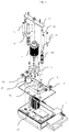
- FIG. 1 shows an exemplary embodiment of an apparatus for using a linear servo motor in a knock out assembly.
- FIG. 2 shows the exemplary embodiment of the apparatus for using a linear servo motor in a knock out assembly in an exploded view.
- FIG. 3 shows an orthogonal view of a base of an embodiment of the apparatus for using a linear servo motor in a knock out assembly.
- FIG. 4 shows an orthogonal view of the base of the embodiment of the apparatus for using a linear servo motor in a knock out assembly.
- the knock out assembly of the present disclosure significantly reduces the number of components as compared to the knock out assemblies using hydraulic systems or complex gear drives.
- FIG. 1 shows an exemplary embodiment of the present disclosure.
- the knock out assembly 1 generally has at least a base 2 , a linear servo motor 11 , a crossbar 12 , return springs 13 , and a knock out device including knock out shafts 14 coupled to knock out cups (not shown).
- the entire assembly may also be covered by an assembly cover 3 .
- the linear servo motor 11 and return springs 13 are attached to the base 2 of the assembly, and one end of each is also attached to the crossbar 12 .
- a first end of a knock out shaft 14 is attached to the crossbar 12 and the second end is coupled to a knock out cup, which is shaped as necessary for the desired food product.
- the knock out shaft 14 extends through the base 2 in order to couple with the knock out cup below the base.
- the return springs 13 may be magnetic springs. Additionally, the number of return springs may be one or more.
- the knock out assembly is not limited to four return springs as shown in the exemplary embodiment. The number of return springs may be different for various considerations. For example, in alternative embodiments, the knock out assembly may have two return springs on each end of the crossbar 12 for a total of 4 return springs. In non-limiting embodiments, these return springs may be aligned along the longitudinal axis of the crossbar 12 or grouped at the ends of the crossbar 12 . In some embodiments, the return springs may be spaced along the crossbar 12 .
- FIG. 1 shows two knock out shafts 14
- alternative embodiments may include differing numbers of knock out shafts 14 .
- the knock out shaft 14 may be directly attached to a singular knock out cup or other tooling.
- the knock out shaft 14 may attach to an intermediate crossbar or other attachment means to which a plurality of knock out cups are attached.
- at least two knock out shafts are coupled together to couple with the knock out cups.
- the knock out cups could be of a variety of shapes in order to form the desired foods.
- linear movement power units could be used. These may include, but are not limited to, solenoid units.
- the primary concern is a power unit that can operate linearly without the need for complex hydraulics or angled gearboxes.
- FIG. 2 shows an exploded view of an exemplary embodiment of the present disclosure.
- a primary mounting bracket 5 is attached by fasteners to the base 2 .
- the primary mounting bracket 5 has a linear servo motor mounting portion 51 and two knock out shaft protrusions 52 .
- the knock out shaft protrusions 52 may be cylindrical and protrude upward from the base.
- the top view cross sectional shape of the knock out shaft protrusions 52 may be another shape, such as a square or triangle.
- the cross sectional shape may be a basis for mounting considerations of related accessories, such as the return springs 13 .
- the knock out protrusions 52 may have a flat portion 55 for attachment of a return spring bracket 6 .
- the knock out protrusions 52 may be a square or triangle such that there is a flat surface for attachment of a return spring bracket 6 . Even in the case of a flat surface, there may still be a ledge or stepped flat portion for mounting of a return spring bracket to enable easier positioning and mounting.
- the knock out shaft protrusions 52 each have a through hole 53 for accepting and guiding the knock out shaft 14 .
- the linear bearing may be a linear ball bearing, bearing pad, or other component.
- the through hole 53 of each knock out protrusion 52 also matches up with through holes 22 in the base 2 . This allows for the knock out shaft 14 to extend out of the base 2 in order to couple with the knock out cups.
- a linear motor mounting bracket 4 may be attached by fasteners.
- the linear motor mounting bracket 4 is attached to the linear servo motor mounting portion 51 of the primary mounting bracket 5 .
- the linear motor mounting bracket 4 may be shaped in order to allow for the proper spacing and mounting of a variety of linear servo motors. The use of a linear motor mounting bracket may allow for removal of the linear servo motor without the need to disassemble the other components of the knock out assembly.
- the linear servo motor 11 can thus be fixedly mounted to the linear motor mounting bracket 4 on top of the primary mounting bracket 5 .
- a driving end of the linear motor mounting bracket is then coupled to the crossbar 12 by fasteners. Accordingly, application of the linear motor can result in vertical movement of the crossbar 12 relative to the base 2 .
- the crossbar 12 is also attached at an outboard location to return springs 13 .
- the return spring 13 is attached on one side to the crossbar 12 and on another side to return spring bracket 6 .
- These return spring bracket 6 is attached to the flat portion 55 of the knock out shaft protrusion 52 of the primary mounting bracket 5 such that the return spring 13 pushes between the crossbar 12 and the primary mounting bracket 5 .
- the return spring 13 may be attached to the crossbar 12 and the return spring bracket 6 at opposing ends of the return spring 13
- the return spring 13 can also be attached to one of the crossbar 12 and the return spring bracket 6 by a moving shaft of the return spring and a location along an outer body casing of the return spring 13 respectively.
- one or more embodiments may have the return spring 13 configured to be attached to the crossbar 12 and to the cover 3 or another fixed element above the crossbar 12 .
- the return spring 13 would be extended when the linear servo motor is in the down position.
- the crossbar 12 is coupled to one end of the knock out shaft 14
- the knock out shaft 14 is coupled to the knock out cups at a second end. Accordingly, when the linear servo motor 11 operates to move the crossbar 12 , the knock out shaft 14 is also moved and the return spring 13 is compressed. This results in the knock out shaft 14 moving downward and also forcing the attached knock out cups towards a mold plate mounted to the food processing machine. Upon this movement, the compressed return spring 13 also exerts a restoring force to return the crossbar to an upward position, thereby lifting the knock out cups from the mold plate.
- the return spring provides a restoring force to return the knock out cups away from the mold plate. This is useful as a loss of power to the linear servo motor without a return mechanism may result in the servo motor dropping downward. As the mold plate in a food processing machine moves in and out of position for knock out, the dropping of the servo motor in a loss of power situation may result in the knock out cups hitting the mold plate and damaging both components. The inclusion of the return spring prevents an uncontrolled drop of the linear servo motor that would result in damage to the knock out cups and mold plate.
- this embodiment provides for the movement of the knock out cups towards the mold plate without the complexities of hydraulic controls or 90 degree gearboxes to translate horizontal rotational motor movement into vertical movement by way of cams.
- FIG. 2 While the embodiment of FIG. 2 has the return spring bracket 6 mounted to a flat portion 55 of the primary mounting bracket 5 , the return spring bracket could alternatively be mounted to the base 2 .
- a plurality of linear servo motors may be positioned on outer portions of the crossbar and the springs positioned on a central or inner portion of the crossbar.
- a plurality of linear servo motors that are synchronized may be used instead of one linear servo motor.
- the shape of the crossbar 12 is generally beam-like in FIG. 1
- alternative shapes may be used.
- a square shaped crossbar or plate could be utilized where the linear servo motor is attached the middle and the return springs are attached at corners of the square shaped crossbar.
- Alternative shapes such as a circle or a triangle could also be used for the crossbar.
- Alternative shapes of the crossbar 12 may also be combined with differing embodiments with different numbers of linear motors, knock out shafts, and return springs.
- the configuration of the springs and linear servo motor may be changed.
- the spring or plurality of springs may be fixed from above the crossbar to another structure of the food forming machinery such that the spring would exert a pulling force to lift the crossbar rather than a pushing force on the crossbar.
- the linear servo motor may be fixed from above the crossbar to another structure of the food forming machinery such that the motor would exert a pushing force to push the crossbar and coupled knock out cups downward into the mold plate.
- Such a structure of the food forming machinery may include the assembly cover 3 . Accordingly, one of ordinary skill would understand various configurations where the springs and linear servo motors may either push or pull on the crossbar.
- brackets in the primary bracket 5 may be integrally formed with the base 2 . In this way, these brackets may be bracket portions of the base 2 rather than separate components.
- FIG. 3 shows the elements related to the base 2 .
- the base 2 includes a central recess 23 for the mounting of the primary bracket 5 and the related components for the linear servo motor 11 .
- the base also includes a heat shield 24 below the base 2 that is attached at a distance away from the base by heat shield standoffs 25 and fasteners.
- the base 2 includes through holes from the recessed portion to the bottom of the base 2 to accommodate knock off shafts 14 .
- embodiments of the base 2 may include a external wiring port 26 connected to an opening in the central recess 23 for running of wiring and other connections from the central recess 23 out of the knock out assembly.
- FIG. 4 further shows the elements related to the base 2 .
- FIG. 4 further shows the inclusion of a radiant heating loop 33 .
- the radiant heating loop 33 may be a resistance heater or other heating element.
- the radiant heating loop 33 may be mounted to the base under the heat shield 24 .
- the radiant heating loop 33 may provide heat in order to maintain a temperature difference between the food product and the knock out cups in order to prevent sticking.
- the radiant heating loop 33 may be positioned underneath the base 2 by attachment to the food forming machinery other than by direct attachment to the knock out assembly.
- the radiant heating loop may be positioned off a mount attaching to the base structure of the food forming machinery.
- a knock out assembly heater 31 can also be attached to the base 2 in order to achieve the temperature difference. This may occur where a food processing machine is not pre-wired for a radiant heating loop in the knock out assembly.
- FIG. 4 shows the base 2 may have a conduit or pipe 32 attached to the external wiring port 26 in order to provide a route for electrical wiring from the various components of the knock out assembly to be routed to the food processing machine.
- the knock out assembly base may be an integrated part of a food processing machine or separate.
- Embodiments of the disclosure may be replacement or bolt-on knock out assemblies for retrofitting on machines, such as the aforementioned hydraulic or cam driven machines.
- the various components of the knock out assembly may be made from a variety of materials, not limited to metals, composites, or plastics. It is noted that various combinations of components of similar or differing materials may be used.
Landscapes
- Engineering & Computer Science (AREA)
- Manufacturing & Machinery (AREA)
- Life Sciences & Earth Sciences (AREA)
- Chemical & Material Sciences (AREA)
- Food Science & Technology (AREA)
- Polymers & Plastics (AREA)
- Connection Of Motors, Electrical Generators, Mechanical Devices, And The Like (AREA)
- Food-Manufacturing Devices (AREA)
Abstract
Description
Claims (13)
Priority Applications (1)
| Application Number | Priority Date | Filing Date | Title |
|---|---|---|---|
| US15/007,957 US10765139B2 (en) | 2015-01-26 | 2016-01-27 | Servo knock out assembly |
Applications Claiming Priority (2)
| Application Number | Priority Date | Filing Date | Title |
|---|---|---|---|
| US201562107783P | 2015-01-26 | 2015-01-26 | |
| US15/007,957 US10765139B2 (en) | 2015-01-26 | 2016-01-27 | Servo knock out assembly |
Publications (2)
| Publication Number | Publication Date |
|---|---|
| US20160213055A1 US20160213055A1 (en) | 2016-07-28 |
| US10765139B2 true US10765139B2 (en) | 2020-09-08 |
Family
ID=56433636
Family Applications (1)
| Application Number | Title | Priority Date | Filing Date |
|---|---|---|---|
| US15/007,957 Expired - Fee Related US10765139B2 (en) | 2015-01-26 | 2016-01-27 | Servo knock out assembly |
Country Status (1)
| Country | Link |
|---|---|
| US (1) | US10765139B2 (en) |
Cited By (1)
| Publication number | Priority date | Publication date | Assignee | Title |
|---|---|---|---|---|
| US12458055B2 (en) | 2021-04-19 | 2025-11-04 | Former Associates, Llc | Servo knock out assembly |
Families Citing this family (2)
| Publication number | Priority date | Publication date | Assignee | Title |
|---|---|---|---|---|
| DE102020115748A1 (en) | 2019-07-04 | 2021-01-07 | Textor Maschinenbau GmbH | Pressing device |
| EP3760047B1 (en) | 2019-07-04 | 2024-12-25 | Textor Maschinenbau GmbH | Pressing device |
Citations (12)
| Publication number | Priority date | Publication date | Assignee | Title |
|---|---|---|---|---|
| US2932246A (en) | 1956-07-02 | 1960-04-12 | Charles P Galas | Meat press |
| US3266442A (en) | 1962-08-31 | 1966-08-16 | American Mach & Foundry | Food preparing apparatus |
| US3417425A (en) | 1966-09-09 | 1968-12-24 | Hollymatic Corp | Molding apparatus for plastic material |
| US3452389A (en) | 1966-12-01 | 1969-07-01 | Fmc Corp | Mechanism for adjusting pockets in food molding machine |
| US3474491A (en) | 1967-06-30 | 1969-10-28 | Hollymatic Corp | Molding apparatus with stacker means |
| US3526924A (en) | 1966-09-09 | 1970-09-08 | Hollymatic Corp | Separator sheet feeder and patty molder |
| US6238196B1 (en) * | 1997-04-24 | 2001-05-29 | Frigoscandia Eguipment Ab | Molding apparatus |
| US20020115402A1 (en) * | 2001-02-22 | 2002-08-22 | Glenn Sandberg | Mold plate having multiple rows of cavities for food patty-molding apparatus |
| US7335013B2 (en) * | 2003-09-16 | 2008-02-26 | Formax, Inc. | Drive systems for a reciprocating mold plate patty-forming machine |
| US20080179793A1 (en) * | 2007-01-26 | 2008-07-31 | Husky Injection Molding Systems Ltd. | Ejector-Plate Actuator of a Molding System |
| US20100209575A1 (en) * | 2009-01-26 | 2010-08-19 | Chris Moore | Linear Actuator Assisted Knockout Mechanism for a Food Patty Forming Machine |
| US20120045534A1 (en) | 2010-07-20 | 2012-02-23 | Lindee Scott A | Patty-Forming Apparatus with Top Feed and Rotary Pump |
-
2016
- 2016-01-27 US US15/007,957 patent/US10765139B2/en not_active Expired - Fee Related
Patent Citations (13)
| Publication number | Priority date | Publication date | Assignee | Title |
|---|---|---|---|---|
| US2932246A (en) | 1956-07-02 | 1960-04-12 | Charles P Galas | Meat press |
| US3266442A (en) | 1962-08-31 | 1966-08-16 | American Mach & Foundry | Food preparing apparatus |
| US3417425A (en) | 1966-09-09 | 1968-12-24 | Hollymatic Corp | Molding apparatus for plastic material |
| US3526924A (en) | 1966-09-09 | 1970-09-08 | Hollymatic Corp | Separator sheet feeder and patty molder |
| US3452389A (en) | 1966-12-01 | 1969-07-01 | Fmc Corp | Mechanism for adjusting pockets in food molding machine |
| US3474491A (en) | 1967-06-30 | 1969-10-28 | Hollymatic Corp | Molding apparatus with stacker means |
| US6238196B1 (en) * | 1997-04-24 | 2001-05-29 | Frigoscandia Eguipment Ab | Molding apparatus |
| US20020115402A1 (en) * | 2001-02-22 | 2002-08-22 | Glenn Sandberg | Mold plate having multiple rows of cavities for food patty-molding apparatus |
| US7335013B2 (en) * | 2003-09-16 | 2008-02-26 | Formax, Inc. | Drive systems for a reciprocating mold plate patty-forming machine |
| US7422425B2 (en) * | 2003-09-16 | 2008-09-09 | Formax, Inc. | Drive system for a knockout apparatus for a patty-forming machine |
| US20080179793A1 (en) * | 2007-01-26 | 2008-07-31 | Husky Injection Molding Systems Ltd. | Ejector-Plate Actuator of a Molding System |
| US20100209575A1 (en) * | 2009-01-26 | 2010-08-19 | Chris Moore | Linear Actuator Assisted Knockout Mechanism for a Food Patty Forming Machine |
| US20120045534A1 (en) | 2010-07-20 | 2012-02-23 | Lindee Scott A | Patty-Forming Apparatus with Top Feed and Rotary Pump |
Cited By (1)
| Publication number | Priority date | Publication date | Assignee | Title |
|---|---|---|---|---|
| US12458055B2 (en) | 2021-04-19 | 2025-11-04 | Former Associates, Llc | Servo knock out assembly |
Also Published As
| Publication number | Publication date |
|---|---|
| US20160213055A1 (en) | 2016-07-28 |
Similar Documents
| Publication | Publication Date | Title |
|---|---|---|
| US10980270B2 (en) | Patty-forming apparatus with top feed and rotary pump | |
| US8613615B2 (en) | Patty-forming apparatus with bottom feed and rotary pump | |
| US10791747B2 (en) | Food processing machine | |
| US7422425B2 (en) | Drive system for a knockout apparatus for a patty-forming machine | |
| US10765139B2 (en) | Servo knock out assembly | |
| US7255554B2 (en) | Cooling air system for a patty-forming apparatus | |
| US8011914B2 (en) | Food supply system for a food patty molding machine | |
| US7721645B2 (en) | Device for keeping a mold plate square, perpendicular and driving for a food product molding machine | |
| US20160255846A1 (en) | Patty-forming apparatus with bottom feed and bottom fill plunger | |
| CN209224176U (en) | A kind of toast slicer | |
| CN203692500U (en) | Grabbing and releasing device of stuffing-filled food forming machine | |
| CN205801663U (en) | The torr box conveying push mechanism of lower case structure | |
| US20230284671A1 (en) | Servo knock out assembly | |
| CA2806028A1 (en) | A patty-forming apparatus with reciprocating mold plate and rotary pump | |
| EP3355711B1 (en) | Cutting arrangement for ice cream machine and method for cutting ice cream | |
| CN109304761A (en) | A kind of device for thermally cutting of deformed thermal-insulating plate | |
| CN102599226A (en) | Poultry processing and air-drying device | |
| CN215702232U (en) | Cutting device for cake production | |
| JP6177303B2 (en) | Skewer feeder for skewer | |
| US20050072634A1 (en) | Lubrication system for a patty-forming apparatus | |
| CN216914802U (en) | Mold device for producing plastic sucking discs | |
| CN102592821A (en) | Rotation preventing device of winding die |
Legal Events
| Date | Code | Title | Description |
|---|---|---|---|
| AS | Assignment |
Owner name: FORMER ASSOCIATES, LLC, WISCONSIN Free format text: ASSIGNMENT OF ASSIGNORS INTEREST;ASSIGNOR:PETROVIC, JAMES;REEL/FRAME:044605/0408 Effective date: 20160127 |
|
| STPP | Information on status: patent application and granting procedure in general |
Free format text: NON FINAL ACTION MAILED |
|
| STPP | Information on status: patent application and granting procedure in general |
Free format text: RESPONSE TO NON-FINAL OFFICE ACTION ENTERED AND FORWARDED TO EXAMINER |
|
| STPP | Information on status: patent application and granting procedure in general |
Free format text: FINAL REJECTION MAILED |
|
| STPP | Information on status: patent application and granting procedure in general |
Free format text: ADVISORY ACTION MAILED |
|
| STPP | Information on status: patent application and granting procedure in general |
Free format text: DOCKETED NEW CASE - READY FOR EXAMINATION |
|
| STPP | Information on status: patent application and granting procedure in general |
Free format text: NON FINAL ACTION MAILED |
|
| STPP | Information on status: patent application and granting procedure in general |
Free format text: RESPONSE TO NON-FINAL OFFICE ACTION ENTERED AND FORWARDED TO EXAMINER |
|
| ZAAA | Notice of allowance and fees due |
Free format text: ORIGINAL CODE: NOA |
|
| ZAAB | Notice of allowance mailed |
Free format text: ORIGINAL CODE: MN/=. |
|
| STCF | Information on status: patent grant |
Free format text: PATENTED CASE |
|
| FEPP | Fee payment procedure |
Free format text: MAINTENANCE FEE REMINDER MAILED (ORIGINAL EVENT CODE: REM.); ENTITY STATUS OF PATENT OWNER: SMALL ENTITY |
|
| LAPS | Lapse for failure to pay maintenance fees |
Free format text: PATENT EXPIRED FOR FAILURE TO PAY MAINTENANCE FEES (ORIGINAL EVENT CODE: EXP.); ENTITY STATUS OF PATENT OWNER: SMALL ENTITY |
|
| STCH | Information on status: patent discontinuation |
Free format text: PATENT EXPIRED DUE TO NONPAYMENT OF MAINTENANCE FEES UNDER 37 CFR 1.362 |
|
| FP | Lapsed due to failure to pay maintenance fee |
Effective date: 20240908 |