US10762606B2 - Image processing apparatus and method for generating high quality image - Google Patents
Image processing apparatus and method for generating high quality image Download PDFInfo
- Publication number
- US10762606B2 US10762606B2 US15/816,678 US201715816678A US10762606B2 US 10762606 B2 US10762606 B2 US 10762606B2 US 201715816678 A US201715816678 A US 201715816678A US 10762606 B2 US10762606 B2 US 10762606B2
- Authority
- US
- United States
- Prior art keywords
- image
- images
- processing apparatus
- features
- image processing
- Prior art date
- Legal status (The legal status is an assumption and is not a legal conclusion. Google has not performed a legal analysis and makes no representation as to the accuracy of the status listed.)
- Active, expires
Links
- 238000012545 processing Methods 0.000 title claims abstract description 100
- 238000000034 method Methods 0.000 title claims description 128
- 230000010354 integration Effects 0.000 claims abstract description 54
- 238000013528 artificial neural network Methods 0.000 claims abstract description 15
- 238000003672 processing method Methods 0.000 claims 1
- 238000009795 derivation Methods 0.000 abstract description 2
- 230000009466 transformation Effects 0.000 description 101
- 230000008569 process Effects 0.000 description 80
- 230000006872 improvement Effects 0.000 description 38
- 230000004048 modification Effects 0.000 description 36
- 238000012986 modification Methods 0.000 description 36
- 238000010586 diagram Methods 0.000 description 35
- 238000006073 displacement reaction Methods 0.000 description 23
- 210000002569 neuron Anatomy 0.000 description 22
- 238000013527 convolutional neural network Methods 0.000 description 15
- 238000000844 transformation Methods 0.000 description 12
- 230000006870 function Effects 0.000 description 10
- 230000010365 information processing Effects 0.000 description 9
- 230000003287 optical effect Effects 0.000 description 8
- 239000013598 vector Substances 0.000 description 8
- 238000012937 correction Methods 0.000 description 7
- 230000007246 mechanism Effects 0.000 description 7
- 238000012935 Averaging Methods 0.000 description 6
- 239000011159 matrix material Substances 0.000 description 6
- 230000004075 alteration Effects 0.000 description 5
- 230000004044 response Effects 0.000 description 5
- 230000009897 systematic effect Effects 0.000 description 5
- 238000004364 calculation method Methods 0.000 description 4
- 230000008859 change Effects 0.000 description 4
- 238000003384 imaging method Methods 0.000 description 4
- 238000011176 pooling Methods 0.000 description 4
- 230000001131 transforming effect Effects 0.000 description 4
- 230000004913 activation Effects 0.000 description 3
- 230000008901 benefit Effects 0.000 description 3
- 230000009467 reduction Effects 0.000 description 3
- 230000015556 catabolic process Effects 0.000 description 2
- 230000000295 complement effect Effects 0.000 description 2
- 238000006731 degradation reaction Methods 0.000 description 2
- 230000000694 effects Effects 0.000 description 2
- 238000003702 image correction Methods 0.000 description 2
- 238000003909 pattern recognition Methods 0.000 description 2
- 238000002360 preparation method Methods 0.000 description 2
- 238000002604 ultrasonography Methods 0.000 description 2
- 230000004931 aggregating effect Effects 0.000 description 1
- 239000003086 colorant Substances 0.000 description 1
- 230000006835 compression Effects 0.000 description 1
- 238000007906 compression Methods 0.000 description 1
- 239000000470 constituent Substances 0.000 description 1
- 238000013461 design Methods 0.000 description 1
- 238000009499 grossing Methods 0.000 description 1
- 238000010606 normalization Methods 0.000 description 1
- 230000002093 peripheral effect Effects 0.000 description 1
- 230000010287 polarization Effects 0.000 description 1
- 238000007781 pre-processing Methods 0.000 description 1
- 238000011112 process operation Methods 0.000 description 1
- 230000001902 propagating effect Effects 0.000 description 1
- 230000003252 repetitive effect Effects 0.000 description 1
- 238000005070 sampling Methods 0.000 description 1
- 238000012706 support-vector machine Methods 0.000 description 1
Images


Classifications
-
- G—PHYSICS
- G06—COMPUTING; CALCULATING OR COUNTING
- G06T—IMAGE DATA PROCESSING OR GENERATION, IN GENERAL
- G06T5/00—Image enhancement or restoration
- G06T5/001—Image restoration
- G06T5/003—Deblurring; Sharpening
-
- G06T5/73—
-
- G—PHYSICS
- G06—COMPUTING; CALCULATING OR COUNTING
- G06T—IMAGE DATA PROCESSING OR GENERATION, IN GENERAL
- G06T5/00—Image enhancement or restoration
- G06T5/50—Image enhancement or restoration by the use of more than one image, e.g. averaging, subtraction
-
- G—PHYSICS
- G06—COMPUTING; CALCULATING OR COUNTING
- G06T—IMAGE DATA PROCESSING OR GENERATION, IN GENERAL
- G06T15/00—3D [Three Dimensional] image rendering
- G06T15/10—Geometric effects
- G06T15/20—Perspective computation
- G06T15/205—Image-based rendering
-
- G—PHYSICS
- G06—COMPUTING; CALCULATING OR COUNTING
- G06T—IMAGE DATA PROCESSING OR GENERATION, IN GENERAL
- G06T5/00—Image enhancement or restoration
-
- G—PHYSICS
- G06—COMPUTING; CALCULATING OR COUNTING
- G06T—IMAGE DATA PROCESSING OR GENERATION, IN GENERAL
- G06T5/00—Image enhancement or restoration
- G06T5/001—Image restoration
-
- G06T5/60—
-
- G—PHYSICS
- G06—COMPUTING; CALCULATING OR COUNTING
- G06T—IMAGE DATA PROCESSING OR GENERATION, IN GENERAL
- G06T2207/00—Indexing scheme for image analysis or image enhancement
- G06T2207/10—Image acquisition modality
- G06T2207/10024—Color image
-
- G—PHYSICS
- G06—COMPUTING; CALCULATING OR COUNTING
- G06T—IMAGE DATA PROCESSING OR GENERATION, IN GENERAL
- G06T2207/00—Indexing scheme for image analysis or image enhancement
- G06T2207/10—Image acquisition modality
- G06T2207/10028—Range image; Depth image; 3D point clouds
-
- G—PHYSICS
- G06—COMPUTING; CALCULATING OR COUNTING
- G06T—IMAGE DATA PROCESSING OR GENERATION, IN GENERAL
- G06T2207/00—Indexing scheme for image analysis or image enhancement
- G06T2207/10—Image acquisition modality
- G06T2207/10048—Infrared image
-
- G—PHYSICS
- G06—COMPUTING; CALCULATING OR COUNTING
- G06T—IMAGE DATA PROCESSING OR GENERATION, IN GENERAL
- G06T2207/00—Indexing scheme for image analysis or image enhancement
- G06T2207/20—Special algorithmic details
- G06T2207/20081—Training; Learning
-
- G—PHYSICS
- G06—COMPUTING; CALCULATING OR COUNTING
- G06T—IMAGE DATA PROCESSING OR GENERATION, IN GENERAL
- G06T2207/00—Indexing scheme for image analysis or image enhancement
- G06T2207/20—Special algorithmic details
- G06T2207/20084—Artificial neural networks [ANN]
-
- G—PHYSICS
- G06—COMPUTING; CALCULATING OR COUNTING
- G06T—IMAGE DATA PROCESSING OR GENERATION, IN GENERAL
- G06T2207/00—Indexing scheme for image analysis or image enhancement
- G06T2207/20—Special algorithmic details
- G06T2207/20212—Image combination
- G06T2207/20216—Image averaging
Definitions
- the present disclosure relates to an image processing apparatus and method for generating a high quality image.
- the known method requires to distort the images with appropriate projective transformation parameters in such a manner that the images are superimposed substantially at the pixel level. Moreover, if a subject has depth, it is required to distort the images according to the areas, considering parallax. Moreover, in the known method, improvement in image quality is based on the image averaging process; therefore, it is difficult to improve a cause of systematic degradation common among the images, such as chromatic aberration and spherical aberration.
- An image processing apparatus includes: an acquisition unit configured to acquire a plurality of images each capturing an identical target and having a different attribute; a derivation unit configured to derive features from the plurality of images, using a first neural network; an integration unit configured to integrate the features derived from the plurality of images; and a generation unit configured to generate a higher quality image than the plurality of images from the feature integrated by the integration unit, using a second neural network.
- FIG. 1 is a diagram illustrating an example of the hardware configuration of an image processing apparatus according to one or more aspects of the present disclosure.
- FIG. 2 is a diagram (No. 1) illustrating an example of the functional configuration of an image processing apparatus according to one or more aspects of the present disclosure.
- FIG. 3 is a diagram illustrating an example of a convolutional neural network according to one or more aspects of the present disclosure.
- FIG. 4 is a schematic diagram illustrating processes of the first embodiment according to one or more aspects of the present disclosure.
- FIG. 5 is a flowchart illustrating an example of information processing of the image processing apparatus according to one or more aspects of the present disclosure.
- FIGS. 6A and 6B are diagrams illustrating examples of a deconvolution operation according to one or more aspects of the present disclosure.
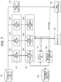
- FIG. 7 is a diagram (No. 2) illustrating an example of the functional configuration of the image processing apparatus according to one or more aspects of the present disclosure.
- FIG. 8 is a flowchart illustrating a learning process of the first embodiment according to one or more aspects of the present disclosure.
- FIGS. 9A to 9C are diagrams for explaining a mechanism for improvement in image quality according to one or more aspects of the present disclosure.
- FIGS. 10A to 10D are diagrams for explaining modifications of the first embodiment according to one or more aspects of the present disclosure.
- FIGS. 11A to 11C are diagrams illustrating examples of an image capture unit according to one or more aspects of the present disclosure.
- FIG. 12 is a flowchart illustrating an example of a learning process of a second embodiment according to one or more aspects of the present disclosure.
- FIGS. 13A and 13B are diagrams illustrating examples of the functional configuration of an image processing apparatus according to one or more aspects of the present disclosure.
- FIGS. 14A to 14C are diagrams for explaining information processing of the third embodiment according to one or more aspects of the present disclosure.
- FIGS. 15A to 15C are flowcharts illustrating examples of the information processing of the image processing apparatus according to one or more aspects of the present disclosure.
- FIGS. 16A to 16F are diagrams illustrating examples of modifications of the third embodiment according to one or more aspects of the present disclosure.
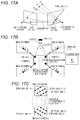
- FIGS. 17A to 17C are diagrams for explaining an epipolar constraint according to one or more aspects of the present disclosure.
- FIGS. 18A and 18B are schematic diagrams of neural networks according to one or more aspects of the present disclosure.
- FIGS. 19A and 19B are schematic diagrams of neural networks according to one or more aspects of the present disclosure.
- FIGS. 20A to 20D are diagrams illustrating examples of application to a multi-camera array according to one or more aspects of the present disclosure.
- FIGS. 21A and 21B are diagrams illustrating examples of learning in stages according to one or more aspects of the present disclosure.
- FIG. 22 is a flowchart illustrating an example of a process of learning in stages according to one or more aspects of the present disclosure.
- FIG. 1 is a diagram illustrating an example of the hardware configuration of an image processing apparatus 10 .
- the image processing apparatus 10 includes a CPU 11 , a memory 12 , a network I/F 13 , and an output I/F 14 as a hardware configuration.
- the CPU 11 controls the entire image processing apparatus 10 .
- the memory 12 stores images, a program, data that is used when the CPU 11 executes processes, and the like.
- the network I/F 13 is an interface that connects the image processing apparatus 10 to a network in a wired or wireless manner.
- the output I/F 14 is connected to, for example, a display, and outputs process results of the CPU 11 , and the like to the display and the like.
- the hardware configuration illustrated in FIG. 1 is an example.
- the image processing apparatus 10 may include a plurality of CPUs, an output unit itself such as a display, interfaces with an image capture unit, an operating unit, and the like, and the image capture unit itself and the operating unit itself.
- the CPU 11 executes processes based on the program stored in the memory 12 to achieve the functional configurations of the image processing apparatus 10 , the functional configurations being illustrated in FIGS. 2, 7, 13A, and 13B , and processes of flowcharts of FIGS. 5, 8, 12, 15A, 15B, 15C, and 22 , which are described below.
- the purpose of the image processing apparatus 10 of the first embodiment is to generate a high quality image that can be obtained by an image capture device with a highly accurate configuration, from a plurality of low quality images of an image capture device with a simple configuration (hereinafter also referred to as the low quality image capture device).
- Resolution enhancement, noise reduction, color correction, sharpening, a change in the depth of field, and the like are conceivable for improvement in image quality.
- improvement in image quality is assumed to indicate resolution enhancement in the embodiment.
- low quality images are assumed to be different in image attribute such as a color image, an infrared image, an image captured with a flash.
- the viewpoint positions of the low quality images and the high quality image generated are assumed to be the same.
- a plurality of images with different attributes from the agreed viewpoint is obtained here by the following method: (1) A ray of light is split in the low quality image capture device, using a half mirror, and (2) Light-sensitive elements with different attributes are mixed and arranged in an image capture device.
- the low quality images acquired by the image processing apparatus 10 are assumed to be those captured by the low quality image capture device designed as described above.
- the image processing apparatus 10 includes image acquisition units 101 a to 101 c for acquiring a plurality of low quality images targeted for image processing, and feature transformation units 102 a to 102 c that transforms the acquired low quality image into features through neural networks (hereinafter abbreviated to NNs), as the functional configuration.
- the image processing apparatus 10 includes a feature integration unit 103 that integrates the features of the NN, an image quality improvement transformation unit 104 that generates a high resolution image on the basis of the integrated feature, and an image output unit 105 that outputs the generated high quality image, as the functional configuration.
- the image processing apparatus 10 includes a transformation parameter retaining unit 106 that retains and supplies various parameters for a feature transformation, as the functional configuration.
- the technique is roughly organized into two parts: (1) a feature transformation process 210 for transforming an enlarged low quality image 202 into a feature 203 of an NN; and (2) an image quality improvement transformation process 213 for generating a high quality image 205 from the feature 203 of the NN.
- the embodiment is described compared with the above known technique.
- a plurality of low quality images 301 a to 301 c is assumed to be input.
- the low quality images are assumed to be images having different attributes such as an RGB color image, an infrared image, and an image captured with a flash.
- FIG. 4 illustrates three low quality images.
- the constituent number of low quality images can be any number equal to or greater than two.
- the processes of the above known technique and the embodiment are different in the respect that a high quality image is complementarily generated using the images with the plurality of attributes.
- the processes of the known technique based on image averaging as in Japanese Patent No. 4942221 and the embodiment are different in the respect that not pixels of an image but features are used and integrated at the time of integration.
- the processes of another known technique and the embodiment are still different in the respect that before integration, each of the images with the plurality of attributes undergoes a feature transformation through its own NN, and is transformed into features with abstractness appropriate for integration.
- the feature connection is illustrated as one implementation mode of the integration of the images.
- the integration method is not limited to the feature connection.
- the image processing apparatus 10 of the embodiment performs feature transformations 308 a to 308 c that transforms the low quality images 301 a to 301 c into features 303 a to 303 c of the CNN.
- the feature transformations 308 a to 308 c each include a two-stage convolution process.
- the image processing apparatus 10 is different from the known technique in the respect of including a process of feature integration 309 .
- the features 303 a to 303 c of the CNN of the low quality images are connected to obtain one feature 304 of the CNN.
- the image processing apparatus 10 performs a process of an image quality improvement transformation 315 on the feature 304 , and obtains a result of a high quality image as a final output.
- the image acquisition units 101 a to 101 c acquire the low quality images 301 a to 301 c in S 101 .
- the acquired images are transmitted to the feature transformation units 102 a to 102 c , respectively.
- the feature transformation units 102 a to 102 c and the image quality improvement transformation unit 104 reads transformation parameters for performing the transformation process from the transformation parameter retaining unit 106 .
- S 103 to S 107 are a loop process of performing the following process for each of the low quality images 301 a to 301 c .
- the feature transformation unit 102 corrects a distortion of an image resulting from, for example, an optical configuration of the low quality image capture device.
- the feature transformation unit 102 adjusts the size and aspect in such a manner that the images agree in size and aspect ratio with each other.
- the feature transformation unit 102 may perform these correction processes using design values of an optical system and the low quality image capture device.
- intrinsic parameters of a camera may be estimated from, for example, a pre-captured pattern for calibration to make corrections.
- the feature transformation unit 102 transforms the low quality images 301 a to 301 c into the features 303 a to 303 c of the CNN. This is based on the following calculations of a convolution and an activation function in the embodiment.
- f i and f i+1 are features before and after the transformation.
- f(x, y, d) is the d-th value of a multidimensional feature f related to a pixel (x, y).
- ⁇ is an activation function of half-wave rectification.
- ⁇ x and ⁇ y are coordinates of each pixel of an image patch of size S ⁇ S, and ⁇ x, ⁇ y ⁇ S/2, . . . , 0, . . . , S/2 ⁇ .
- w is a transformation parameter of a fourth-order tensor.
- b is a bias term. An area outside the image is filled with a value of 0. The size of the image is assumed to be unchanged before and after a convolution operation.
- the parameters w and b of the convolution operation are acquired in advance in a case learning method illustrated below.
- the convolution operation can be qualitatively assumed to be a coding process of a local patch for associating a low quality image with a high quality image being a post-transformation target.
- An image is considered to be a set of small local patches.
- the image has spatial continuity.
- the same subject such as a sky or a wall has a repetitive pattern and a similar pattern.
- each patch can be efficiently approximated by a combination of codebooks of a finite number of patterns. This is codebook-based image compression.
- Each patch of the image is compressed into a codebook and its coefficient (coding), and the image can be generated from the sum of products of the coefficient and the codebook (decoding).
- the image processing apparatus 10 of the embodiment also performs a partially similar process to the above process. What is different is that an image targeted for decoding is not an input image itself but a high quality image. Moreover, an information representation of a codebook in a middle stage is required to sufficiently represent high definition information and be robust against noise and the like.
- a feature representation of an NN is adequate for this.
- Various pieces of information such as a combination of colors and the shape of an object are represented in different hierarchical levels in the layers of a CNN where a convolution operation is repeated a plurality of times.
- a necessary type of representation is heuristically acquired according to the learned task.
- the above description is the background of a convolution operation of an NN to achieve a feature representation (coding) for improvement in image quality.
- FIG. 4 illustrates a mode in which the above convolution operation is performed in two stages as each process of the feature transformations 308 a to 308 c .
- the number of stages of the convolution operation, the size of a convolution kernel at that time, the number of dimensions of a transformed feature, and the like are not limited to specific modes.
- the transformation parameters of the feature transformations 308 a to 308 c may be different from each other.
- the feature integration unit 103 integrates the features 303 a to 303 c of the CNN obtained in the former stage, and generates the integrated feature 304 .
- f 2a (x, y), f 2b (x, y), and f 2c (x, y) are feature vectors related to the pixel (x, y) of the features 303 a to 303 c of the CNN, respectively, and T is the transpose.
- the image quality improvement transformation unit 104 performs a process of a deconvolution 310 on the integrated feature 304 .
- a 1 ⁇ 1 ⁇ D 3 -dimensional feature of each pixel is transformed into an S ⁇ S ⁇ D 4 -dimensional feature.
- FIG. 6A is a schematic diagram illustrating a case where the size of the transformed image patch is equal to S.
- FIG. 6B illustrates a case where each transformed image patch is larger in size than S. In the latter case, an area overlapping between the transformed image patches is present. The value of each transformed pixel is summed in the overlapping area to use the sum as a feature.
- the image processing apparatus 10 of the embodiment improves the resolution on the basis of case learning as described below, and weights are optimized through all the layers of the NN.
- the image quality improvement transformation unit 104 performs a process of a convolution 311 and a process of a convolution 312 on the high image quality feature 305 of FIG. 4 , and obtains a color image 307 having three channels.
- the image output unit 105 outputs a resultant high quality image. The image output unit 105 then ends the process of the flowchart illustrated in FIG. 5 .
- Parameters related to a series of transformations of the embodiment are acquired by learning in advance appropriate pre- and post-transformation relationships between an image and a feature from multiple case images. The operation at the time of learning is described below.
- a process of normalizing the value of a feature may be combined with each stage of the NN. The detailed contents of variations of such a process are not an essential element for the embodiment. Therefore, they are not described in detail here.
- FIG. 7 A functional configuration diagram of the image processing apparatus 10 related to learning is as illustrated in FIG. 7 .
- This configuration includes a high quality image acquisition unit 107 , an image comparison unit 108 , and a learning case image retaining unit 109 , which have been newly added to FIG. 2 .
- a flowchart of a learning process is described using FIG. 8 .
- a set of case images used for learning is assumed to be obtained by capturing in advance images of various subjects, and saving the images in the learning case image retaining unit 109 .
- the case images here include a group of low quality images captured by the image acquisition units 101 a to 101 c and a high quality image being a final target to be generated from the group of low quality images.
- An image capture device different from a group of low quality image capture devices is prepared to capture the high quality image. It is assumed here that the position of the image capture device is adjusted in such a manner as to make the viewpoint and focal plane the same as the group of low quality images to capture the high quality image.
- the transformation parameter retaining unit 106 initializes all the parameters ⁇ w i , b i , w′ i , b′ i ⁇ with random numbers first in S 201 .
- the image acquisition units 101 a to 101 c read the low quality images of the image capture systems from the learning case image retaining unit 109 , and perform a transformation in such a manner as to substantially align the subjects in the low quality images by correcting the distortion, size, and aspect of each image.
- the determined transformation parameters for image correction are saved in the transformation parameter retaining unit 106 .
- the same values are also used at the time of recognition.
- the image acquisition units 101 a to 101 c return the corrected images to the learning case image retaining unit 109 and save them therein.
- this image correction does not always need strict agreement at the pixel level.
- the displacement manner is systematic.
- the same edge between the low quality images is always shifted by the same displacement.
- a filter whose center of the receptive field is displaced is learned for each of the feature transformations 308 a to 308 c of the low quality images in FIG. 4 .
- a displacement is absorbed in the above transformation.
- the features are then integrated in the feature integration 309 , and further transmitted to neurons in a higher layer to be associated with the high quality image.
- a displacement occurs non-systematically.
- filters whose centers of the receptive fields are blurred are learned for the feature transformations 308 a to 308 c .
- the size of the blur is proportional to a standard deviation of the non-systematic displacement between the low quality images. In this manner, the displacement between the low quality images is robustly absorbed by the filter of the NN.
- the next processes from S 204 to S 210 are a loop to update a parameter to reduce an error in such a manner as to bring a transformation result close to a target image.
- the loop is repeated a predetermined number of times.
- the image acquisition units 101 a to 101 c select n sets of low quality images.
- the high quality image acquisition unit 107 acquires n high equality images on the same focal plane from the same viewpoint corresponding to each set of low quality images.
- the feature transformation units 102 a to 102 c , the feature integration unit 103 , and the image quality improvement transformation unit 104 perform the transformation process in a predetermined order, using the values of the parameters for the transformation obtained up to this point. Consequently, the n high quality images are generated from the n sets of low quality images.
- the image comparison unit 108 compares the generated n high quality images with n target high quality images, and calculates errors. A sum of the errors between the images is defined by the following squared error.
- I* j is a true value of the j-th high quality image among the n data sets.
- I ⁇ circumflex over ( ) ⁇ j is a high quality image generated from the j-th set of low quality images.
- m j is a total number of pixels of the j-th image.
- c is an element representing three channels of RGB.
- the image comparison unit 108 transmits error values to the feature transformation units 102 a to 102 c and the image quality improvement transformation unit 104 .
- the parameters ⁇ w i , b i , w′ i , b′ i ⁇ are changed by the following equation in such a manner as to minimize the error values.
- W ( t+ 1) W ( t ) ⁇ L/ ⁇ W ( t )
- W represents any of the parameters.
- ⁇ is a learning coefficient.
- the error gradient term, ⁇ L/ ⁇ W is sequentially calculated from the final layer, using the backpropagation technique.
- ⁇ L/ ⁇ W ij ( ⁇ L/ ⁇ Z j )( ⁇ Z j / ⁇ W ij )
- Z j is an output value of the neuron j.
- the above update process is repeated a predetermined number of times.
- the feature transformation units 102 a to 102 c , the feature integration unit 103 , and the image quality improvement transformation unit 104 then save all the parameters of the network in the transformation parameter retaining unit 106 , and ends the process.
- There are also various derivative forms such as a type where a term called an inertial term or a weight attenuation term is added to the above learning update equation. The description of the process at the time of learning is finished here.
- low quality images 501 a to 501 c whose attributes are different from each other, such as an infrared image, a luminance image, and a depth image, are captured and input.
- the images are assumed to be images which have a low resolution and noise as in the luminance image 501 b , which includes fringes along boundaries due to chromatic aberration as expressed by a double line in the infrared image 501 a , and which blurs over the entire surface as in the depth image 501 c.
- the image processing apparatus 10 transforms each image into features through the NN.
- An area of each image is decomposed into abstract high dimensional features related to the appearance of a subject, such as the shape of a contour and the texture of a surface.
- the image processing apparatus 10 connects and integrates features 502 a to 502 c of the plurality of images.
- the images of the different attributes are then aggregated at a feature level.
- the case-based learning allows the high dimensional feature vector and a pattern 504 of a local area of a high quality image 503 being a post-transformation target to be associated and stored.
- all the transformation parameters of the layers of the NN are optimized through the learning. In such a mechanism, the image processing apparatus 10 of the embodiment can generate the high quality image 503 using the group of low quality images of the different attributes.
- a known image quality improvement method is compared here.
- Known methods that use different attribute images complementarily include a method described in Qiong Yan, Xiaoyong Shen, Li Xu, Shaojie Zhuo, Xiaopeng Zhang, Liang Shen, and Jiaya Jia, Cross-Field Joint Image Restoration via Scale Map. IEEE International Conference on Computer Vision (ICCV), 2013.
- edges are extracted from an infrared image captured by an infrared flash, and edge-preserving smoothing are performed on a visible light image using the edges.
- Such a method requires to adjust the position of an edge and individually handle noise such as a missing edge and a pseudo-edge of the infrared image.
- a case is considered in which there are a discrepancy in edge between low quality images and a discrepancy such as fringes of color due to aberration.
- Local patches of a low quality image include partial areas of various subjects. Many patches of similar contours and textures are extracted from the same subject such as a sky or wall. If a discrepancy between two different types of images is systematic, and the contours are always displaced by the same amount in the same direction, then there are multiple patches including similar displacements of contours.
- an NN transforms local patches into features (coding)
- the weights of a convolution operation are learned also taking their displacements as a part of the pattern.
- the discrepancy between the images is absorbed by the feature transformation of the NN.
- a discrepancy between different types of images is absorbed by learning to enable complementary use of each image.
- a user does not need to individually handle discrepancies between the different types of images.
- Japanese Patent No. 4942221 is further compared.
- a user gives the value of an image to be synthesized on a virtual focal plane.
- the positions of a group of images are displaced accordingly, and the images are superimposed and averaged.
- the above-mentioned process is not performed.
- the image processing apparatus 10 of the embodiment deals with an image having a different focal plane as another learning case even if a subject is the same. In learning, a correspondence relationship between a feature of a low quality image and a local area of a high quality image is stored according to the case where the focal plane is different.
- the image processing apparatus 10 transforms the images in such a manner as to reproduce a high quality image captured on the corresponding focal plane.
- the image processing apparatus 10 performs the image quality improvement process on a case basis.
- image quality improvement process not limited to resolution enhancement but various modes can be achieved.
- image quality improvement processes such as dark current noise reduction, color correction, sharpening, a change in depth of field, removal of a blur, and removal of a fog and a haze can be achieved.
- a low quality image carries necessary information to distinguish a signal and noise, and that a wide selection of cases is prepared to learn cases.
- a multi-band (for example, infrared) image that can capture a subject hidden in the fog to some degree.
- a wide selection of case sets that allow learning of a difference between a dark current and a normal pattern is required.
- the image processing apparatus 10 may be configured as in FIG. 10A as a modification of the first embodiment. Unlike the first embodiment described above, the image processing apparatus 10 of the modification performs an image quality improvement process first by a deconvolution on features 903 a and 903 b of low quality images, and generates high image quality features 904 a and 904 b . The image processing apparatus 10 subsequently performs a feature connection process. In this manner, there can be modes where the order of the processes is reversed, or the process is separated into a plurality of stages, and executed. Moreover, the high resolution transformation of a deconvolution may be separated into a plurality of phases and is made little by little into high image quality features.
- a deconvolution operation based on learning is used to obtain a high image quality feature.
- the image processing apparatus 10 may upsample low quality images 911 a and 911 b first by a general image processing technique such as bicubic interpolation, and transform them into features of NNs.
- the image processing apparatus 10 may use a two-stage transformation including an enlarged copy of a feature called unpooling and a convolution operation, which is illustrated in Alexey Dosovitskiy, Jost Tobias Springenberg, and Thomas Brox, Learning to Generate Chairs with Convolutional Neural Networks. Proceedings of 28th IEEE Conference on Computer Vision and Pattern Recognition (CVPR), 2015, instead of a deconvolution operation.
- the image processing apparatus 10 may be in a mode that performs a feature transformation also for resolution enhancement by a deconvolution operation in the first stage, and then performs feature integration and image quality improvement.
- the image processing apparatus 10 may be in a mode that regards an image itself as features, connects all channels of images of different attributes in the first stage, and then performs the image quality improvement transformation by a convolution.
- the image processing apparatus 10 may combine a pooling process.
- Pooling is a process of aggregating features of a plurality of pixels into a feature of one pixel, and has an effect that the response of a neuron is robust against the distortion and displacement of a pattern.
- the spatial resolution of a feature is reduced.
- the image processing apparatus 10 may enlarge a feature again by linear interpolation or the like after pooling, and restore the resolution by a deconvolution operation.
- FIG. 10D illustrates an example of a part of the modification. A configuration is illustrated here in which pooling is performed after the convolution operation, features between the different attributes are connected, and the resolution is enlarged again by a deconvolution operation.
- the transformation parameters of a convolution and a deconvolution are constant irrespective of the position in an image.
- different parameters may be used according to the position in an image. In this modification, it can be expected to effectively learn and remove the causes of degradation such as specific aberration and reduction in peripheral brightness, which are likely to occur at an end of an image.
- the image processing apparatus 10 may use, as low quality images, image data by special imaging techniques called, for example, coded imaging and compressed sensing.
- coded imaging and compressed sensing For example, Levin, A., Fergus, R., Durand, F., and Freeman, W. T., Image and depth from a conventional camera with a coded aperture.
- ACM Trans. Graph. 26, 3 (2007), 70 illustrates an example where when an image captured with an aperture of a special mask pattern called a coded aperture is used, the depth estimation of a subject is facilitated.
- image data as in the document may be used. When such image data and a normal luminance image are combined, images having different properties can be complementarily used. Accordingly, the accuracy can be expected to be improved.
- low quality images are adjusted in focal plane and captured.
- it may be configured in such a manner that one of the low quality images is set as a reference image, the focal plane is operated to perform image capture, and the focal plane of the remaining low quality images is always fixed. Images other than the reference image are images captured at a large depth of field (what is called deep focus).
- information on the focal plane is used as a clue from the reference image, and only information on appearance is used from the remaining images. Consequently, as in the previous modes, a high quality image such as captured on a focal plane corresponding to a focal plane of an input image is generated.
- the configuration is described in which the viewpoint positions of each low quality image obtained by the image acquisition unit of the image processing apparatus 10 and a high quality image obtained by transforming the low quality images are the same.
- a configuration is described in which the viewpoint positions of each low quality image and a high quality image are different.
- the embodiment has a simpler configuration since the embodiment does not need the splitting of a light ray, and the like, unlike the first embodiment.
- parallax that does not occur in the first embodiment occurs between images. Accordingly, more complicated image transformation parameters need to be learned.
- the image processing apparatus 10 of the embodiment is assumed to include an image capture unit 1000 as a hardware configuration.
- FIG. 11A illustrates an example of an external view of the image capture unit 1000 .
- a housing of the image capture unit 1000 includes two low quality image capture devices 1011 a and 1011 b .
- the purpose of the process of the embodiment is to generate an image such as captured by a high quality camera at a virtual viewpoint position 1012 from low quality images captured by the two low quality image capture devices.
- FIG. 11B let a displacement between the viewpoint position of the i-th low quality image capture device and a virtual viewpoint position of a high quality image be pi.
- the functional configuration of the embodiment is similar to that of FIG. 2 of the first embodiment.
- FIG. 12 The functional configuration diagram at the time of learning is similar to that of FIG. 7 of the first embodiment.
- a high quality image capture device for capturing high quality learning image data is separately prepared as a preparation for a learning process. It is assumed to include a system that can capture images while freely and individually moving viewpoints of the high quality image capture device and the low quality image capture devices 1011 a and 1001 b.
- the learning case image retaining unit 109 captures an image of a subject for learning with the high quality image capture device, and saves the image in S 301 .
- the learning case image retaining unit 109 captures images of the same subject with the two low quality image capture devices 1011 a and 1001 b , and saves the images.
- the learning case image retaining unit 109 performs image capture a plurality of times while displacing the positions of viewpoints of the low quality image capture devices 1011 a and 1001 b by a predetermined displacement in a horizontal direction. Consequently, high quality images of various subjects and a plurality of low quality images obtained by capturing the same subjects in different parallaxes are saved in the learning case image retaining unit 109 .
- S 303 to S 307 are a loop to learn and update each transformation parameter.
- a variable a is incremented by 0.1 from zero to one.
- the high quality image acquisition unit 107 selects and acquires n high quality images from the learning case image retaining unit 109 .
- the image acquisition units 101 a and 101 b each select and acquire n images corresponding to the high quality images from the learning case image retaining unit 109 .
- the image acquisition units 101 a and 101 b each select images captured at a position of a displacement ⁇ i according to the value of ⁇ , respectively, as illustrated in FIG. 11C .
- the feature transformation units 102 a and 102 b and the image quality improvement transformation unit 104 update the transformation parameters.
- This step includes S 306 a to S 306 c .
- This process is the same as the process operation (S 207 to S 209 of FIG. 8 ) at the time of learning described in the first embodiment. Accordingly, its detailed description is omitted.
- the feature transformation units 102 a and 102 b and the image quality improvement transformation unit 104 save the transformation parameters of the NNs in the transformation parameter retaining unit 106 in S 309 .
- the feature transformation units 102 a and 102 b and the image quality improvement transformation unit 104 then end the process of the flowchart illustrated in FIG. 8 .
- the feature representation vectors (P L , Q, R R ) are stored associated with an appearance 504 in a local area of a high quality image 513 .
- the feature representation vectors (P LL , Q, R RR ) are associated with an appearance 505 when the same local area is captured in a near distance. In this manner, each pattern is associated with the high quality image and stored.
- the vectors of responses of neurons for the sets of patterns ⁇ P, P L , P LL ⁇ and ⁇ R, R R , R RR ⁇ are a one-dimensional manifold.
- a set of the vector groups ⁇ (P, Q, R), (P L , Q, R R ), (P LL , Q, R RR ) ⁇ is also a one-dimensional manifold.
- a response pattern of a neuron is a high-dimensional manifold also having variations in shape other than displacement.
- the topic is limited only to displacement for simplicity.
- An NN is publicly known as a technique that allows a manifold pattern to be efficiently learned, and especially an autoencoder to reduce the dimension of a manifold pattern is widely known.
- the image processing apparatus 10 of the embodiment reduces the dimension of a high-dimensional input image pattern to features of the NN, ties the features to an output image pattern, and decodes them back to the image.
- This can regard the input and output data as a type of autoencoder that is asymmetrical between low image quality and high image quality.
- the mode is described in which viewpoint positions of each low quality image and a high quality image are not the same.
- viewpoint positions are apart, and parallax occurs to such an extent as to exceed the size of the receptive field of a neuron, images cannot be associated. Accordingly, there is a problem reducing the accuracy.
- the receptive field of a neuron in a higher layer can be increased in size.
- an NN having multiple layers has a difficulty in learning.
- various modes including, but not limited to, the operation of connecting features, can be taken by the feature integration unit in the embodiment.
- the image processing apparatus 10 of the embodiment includes a plurality of image acquisition units that acquire low quality images from different viewpoint positions as in the second embodiment.
- the purpose of the process of the image processing apparatus 10 is assumed to create an aesthetically pleasing image with a small depth of field such as captured with a large aperture lens, from a plurality of low quality images acquired.
- a high quality image can be obtained also from an optical system whose physical size is small or configuration is simple.
- FIG. 13A The functional configuration of the image processing apparatus 10 is as illustrated in FIG. 13A .
- FIG. 13A is different from the previous embodiments in the following two respects: one is the inclusion of a subject distance acquisition unit 1007 , and the other is the inclusion of M feature transformation units 1002 x to 1002 z corresponding to a parallax of a pattern.
- FIGS. 14A, 15A , and 15 B The information processing of the image processing apparatus 10 is described using FIGS. 14A, 15A , and 15 B.
- the image processing apparatus 10 initiates its operation, similar processes to the above embodiments are performed in S 401 to S 406 .
- low quality image acquisition units 1001 a to 1001 c acquire N images, and correct distortions and sizes of the images. If optical axes of the low quality image capture devices and a virtual viewpoint position of a high quality image are not parallel at the time of distortion correction in S 404 , the image processing apparatus 10 makes a correction together by a projective transformation in such a manner as to make image planes of the low quality images and the high quality image parallel.
- S 407 to S 410 are a loop of a process of performing M different feature transformations on the set of low quality images obtained in the previous stage.
- the M feature transformations correspond to cases of M different parallaxes, respectively.
- the feature transformation units 1002 x to 1002 z assume that there is a subject on a focal plane at a distance d j , and displace the images by a predetermined amount in a predetermined direction in such a manner that the positions of all the images agree on the focal plane, and superimpose the images.
- the N superimposed images are represented in a symbol I (j) in FIG. 14A .
- the feature transformation units 1002 x to 1002 z uniformly perform the above process irrespective of the distance to the subject during image processing.
- a convolution operation unit included in the feature transformation unit 1002 performs a convolution operation on the image I (j) to obtain a feature f 1 (j) of the NN.
- the feature integration unit 1003 obtains a distance map D* from the subject distance acquisition unit 1007 .
- the distance map it is assumed that the value of a distance of each pixel is obtained separately by any means such as an active pattern irradiation method at the same time as image capture.
- the realization means of the subject distance acquisition unit 1007 does not matter here.
- the feature integration unit 1003 selects one of M types of features f 1 (1) (x, y) for each pixel on the basis of a value d*(x, y) ⁇ D* of the distance map, and obtains a feature f 2 (x, y).
- the feature f 1 (j) (x, y) corresponding to the distance d j closest to d*(x, y) is set as a feature of f 2 (x, y).
- the image quality improvement transformation unit 1004 performs a convolution operation on the feature f 2 , and generates a high quality image.
- the image output unit 1005 outputs the generated image.
- the image output unit 1005 then ends the processes of flowcharts of FIGS. 15A and 15B .
- the information processing of the image processing apparatus 10 of the embodiment has been described up to this point.
- a deconvolution operation is not used unlike the first and second embodiments. This is because the purpose of the embodiment is not to improve the resolution of an image but to obtain an aesthetically pleasing high quality image such as captured with a large aperture lens.
- FIG. 13B illustrates the functional configuration diagram of the modification of the embodiment.
- FIG. 14B illustrates a schematic diagram.
- FIG. 15C illustrates the information processing of the modification.
- the image processing apparatus 10 of the modification includes a corresponding point determination unit 1008 instead of the subject distance acquisition unit 1007 .
- feature transformations are performed on M different parallaxes. Up to this point the process is similar to the above.
- the pattern corresponding point determination unit 1008 determines whether or not each pixel of a set I (j) of N images is a corresponding point in a predetermined distance, and outputs the result.
- the method for determining a corresponding point is described below.
- the corresponding point determination unit 1008 makes the above-mentioned determination according to assumed M distances d j .
- the feature integration unit 1003 performs a weighted sum of the features f 1 of each pixel of the M patterns on the basis of the following equation for integration into one feature f 2 , in S 422 .
- l COR (j) represents the likelihood of whether or not the same point of the subject at the distance d j is projected into the image set I (j) .
- the corresponding point determination unit 1008 is an NN including a network of a convolution operation and full connections.
- the NN performs a transformation process on an input image patch group, and outputs a likelihood 1009 of a corresponding point of one variable as the final output.
- the likelihood 1009 of the corresponding point is a score obtained by determining whether or not the same position of the subject appears at the center of the image patch group. Weights of each layer of the NN are learned in advance, using case images for learning, to allow the appropriate output of the likelihood score.
- the likelihood integration unit 1003 receives the corresponding point features 1010 of the M patterns and the features f 1 (j) of the NN of the M patterns, connects them, and obtains a high-dimensional feature f 2 .
- the NN in the subsequent stage learns with the high-dimensional feature f 2 as an input, image quality can be improved without failure even in a case where the determination of a corresponding point fails.
- FIG. 16A illustrates a schematic diagram.
- the image capture unit of the embodiment includes an image capture device 1030 a that captures an RGB image, an image capture device 1030 b that captures an infrared image, and an infrared flash 1020 .
- a virtual viewpoint position 1030 of a transformed high quality image is the same as a viewpoint position of the image capture device 1030 a .
- an infrared flash is projected at the time of image capture, and the image capture device 1030 a captures an RGB color image and the image capture device 1030 b an infrared image at the same time.
- the images are used as low quality images.
- a high quality image for learning including the same subject is assumed to be an image with little noise obtained by being exposed by the image capture device 1030 a to light for a long time.
- the operations of the following image quality improvement process and learning process are common to the third embodiment. Accordingly, the details are omitted. Up to this point it has been illustrated that the mode of the third embodiment can be applied to the image quality improvement process having another purpose. In addition, various modes can be employed.
- a transformation may be performed in such a manner as to obtain an RGB color image such as captured frontlit, from an RGB color image of a person captured backlit, and an infrared image captured using the infrared flash as illustrated in a schematic diagram of FIG. 16C .
- images of various attributes can be used as follows.
- an image with a wide dynamic range of brightness may be generated from a group of low quality images captured by low quality image capture devices from a plurality of viewpoints, the group of low quality images having been exposed to light for different periods of time, as illustrated in a schematic diagram of FIG. 16D .
- an image captured by a low-field MRI apparatus and an image of a different attribute, such as an ultrasound image or X-ray image, obtained by capturing the same subject are combined, as illustrated in a schematic diagram of FIG. 16E . Consequently, an image with definition as high as an image captured by a high-field MRI apparatus, or voxel data may be obtained.
- a combination of images is appropriately selected and accordingly a low invasive and high quality medical image can be obtained.
- the attribute of an image may be converted as in a case where a plurality of ultrasound images is used as inputs, and an X-ray image is used as a target image.
- a plurality of results may be output at the same time.
- a map in the direction of a normal to a surface of a subject, and a depth image (2.5-dimensional image) may be generated at the same time from a plurality of low quality image capture devices including a plurality of filters whose polarization directions are different. It may be configured in such a manner that when a plurality of transformations of different purposes is performed, as long as tasks are related, some layers of an NN are used in common up to some midpoint, and only a high layer of the NN for image generation is separately prepared for each task and learns. It is more advantageous in terms of scale than a preparation of two different NNs for the image processing apparatus 10 .
- the mode has been described in which low quality images from different viewpoint positions are integrated to generate a high quality image. Furthermore, it has been illustrated as the mode of the feature integration unit 103 that a selection on a pixel by pixel basis and a weighted sum (weighted average) of each pixel are possible other than the connection of features illustrated in the first embodiment. In this manner, various modes are conceivable for the feature integration unit 103 , and the feature integration unit 103 is not limited to a specific mode.
- a mode is described in which a connectivity relationship of an NN is determined on the basis of a geometric positional relationship of low quality image capture devices.
- the functional configuration diagram is the same as FIG. 13B used in the third embodiment. However, the embodiment does not require the corresponding point determination unit 1008 unlike the third embodiment.
- An image capture unit of the image processing apparatus 10 of the embodiment includes four low quality image capture devices (cameras 1 to 4 ) whose optical axes are parallel as illustrated in FIG. 17B .
- FIG. 17B illustrates a virtual viewpoint position of a high quality image in the form of a broken line circle.
- FIG. 17C illustrates only part of the correspondence relationships with broken lines.
- a layer 1800 of neurons which is a first layer, has one neuron for each pixel x, y of a target high quality image I*(x, y). Each neuron has N feature channels. This is expressed in a symbol f 1 (x, y) ⁇ R N .
- M such neuron layers are prepared corresponding to M parallaxes (depths). The feature of a neuron is expressed in a symbol f 1 (j) (x, y) ⁇ R N with j as a parallax number.
- FIG. 18A illustrates a more specific example.
- a pixel 1801 of the image of the camera 1 and a pixel 1802 of the image of the camera 2 correspond to a pixel 1805 at the center of a feature f 1 (1) (x, y).
- a pixel 1803 of the image of the camera 1 and a pixel 1804 of the image of the camera 2 correspond to a pixel 1806 at the center of a feature f 1 (M) (x, y).
- the value of a pixel of the i-th image is assumed to be input into the i-th channel of each neuron.
- the weight of a connection of input is assumed to be one, that is, an identity function.
- the input relationship between each neuron and an image can be uniquely determined by an epipolar constraint and parallax.
- a homography matrix is obtained as described below to accurately obtain a correspondence relationship in reality.
- the homography matrix is a 3 ⁇ 3 transformation matrix where a position x when viewing the point X ⁇ on the plane ⁇ from one image projects into the other image, on a position x′.
- N low quality images are acquired.
- the feature transformation units 1 to M transform the N low quality images into the features f 1 (l) to f 1 (M) of the NN. Furthermore, the feature transformation units 1 to M perform a convolution operation on the features f 1 (1) to f 1 (M) to obtain features f 2 (1) to f 2 (M) of the NN.
- f 2 (1) to f 2 (M) are features that represent what kind of appearance pattern such as an edge and texture is present at each position when the space is divided into M levels from near to far.
- the feature integration unit 1003 of FIG. 13B connects the features f 2 (1) to f 2 (M) to obtain a feature f 3 .
- the image quality improvement transformation unit 1004 performs a convolution on the feature f 3 to generate a high quality image I*.
- an image quality improvement transformation a process of integrating high-dimensional features divided at near and far positions and associating the feature with a local area of a high quality image to perform a transformation is performed.
- the learning method of transformation parameters in each layer is similar to the above.
- the connectivity relationship between a low quality image and a first layer of the NN is determined on the basis of a geometric constraint condition between images.
- a connectivity relationship may be acquired automatically.
- the image processing apparatus 10 prepares fully connected weights between all pixels of an input image and neurons in the first layer of the NN to initialize them with random numbers.
- the image processing apparatus 10 presents calibration patterns whose examples are illustrated in FIG. 18B in various positions, and learns the weights by the backpropagation method in such a manner that the same patterns can be generated in the first layer of the NN.
- the calibration patterns those including patterns of a luminous point only near the center, a grid in a specific direction, and random dots are suitable to facilitate learning of the connectivity relationship, as illustrated in FIG. 18B .
- the image processing apparatus 10 advances learning, removes the weight that has approached zero assuming that the weight is irrelevant to a corresponding point, and employs the remaining connections.
- the first layer 1800 of the NN is learned individually according to the parallax.
- a calibration pattern captured with a corresponding parallax is provided as a learning image.
- the mechanism for automatically acquiring the connectivity relationship between each pixel and the first layer of the NN has been described above. In the case of this method, there is an advantage in being able to input a captured image as it is without pre-processing of distortion correction.
- the image processing apparatus 10 may further adjust weights in all the layers from the final output layer to the input layer by the backpropagation method on the basis of learning images.
- the information processing of the image processing apparatus 10 of the embodiment indicates to determine the connectivity relationship of an NN from a geometric positional relationship of image capture devices, and to learn the weight of each connection with case images.
- FIG. 19A is a schematic diagram of an image quality improvement process corresponding to the image capture unit.
- the image processing apparatus 10 integrates features sequentially from low quality images captured by low quality image capture devices whose viewpoint positions are close to each other, among low quality image capture devices to which symbols A to H are assigned in FIG. 19A .
- the image processing apparatus 10 divides such integration into three stages, repeats the integration, and obtains a final transformation result of a high quality image, as illustrated in FIG. 19B .
- the advantage in sequential integration starting with image capture systems close to each other as in the embodiment is a point that a displacement between images due to parallax is small in each integration stage. Hence, it is possible to easily absorb the displacement of an appearance resulting from parallax by a feature transformation by a convolution operation and the like, and perform integration.
- a high quality image captured from a virtual viewpoint position is provided as a target image, and transformation parameters in all the stages are learned in such a manner as to generate the target image from low quality images. This is simply required to learn while propagating an error through all the three layers from the final layer to the first layer by the backpropagation method.
- the image processing apparatus 10 integrates images acquired by each group of 2 ⁇ 2 neighboring image capture devices first as the first integration stage as illustrated in FIG. 20B .
- the image processing apparatus 10 obtains four integrated features as a result of the integration process in the first stage, further connects the four features in the second stage of the integration process to obtain one feature, and generates a high quality image.
- the NN equal to one stage for image integration includes three layers of a feature transformation (a convolution operation 2101 ), integration (a connection process 2102 ), and image generation (a convolution operation 3000 ).
- the integration of images is performed on images of 2 ⁇ 2 low quality image capture devices in a neighboring area. Examples of the integration areas are illustrated in FIG. 21A , enclosed in a black frame and a gray frame as an integration area 1 and an integration area 2 , respectively.
- the integration areas overlap with each other as in FIG. 21A . Transformation parameters of the NN are learned independently in each integration area.
- FIG. 21B illustrates only one NN in each stage among the columnar NNs having three layers where integration is performed, of an NN in each stage.
- 3 ⁇ 3, 2 ⁇ 2, and 1 ⁇ 1 columnar NNs having three layers are present respectively in the first, second, and third stages.
- the image processing apparatus 10 obtains 3 ⁇ 3 integrated features as a result of the integration in the first stage.
- the image processing apparatus 10 integrates the 3 ⁇ 3 features successively in the second and third stages, and obtains 2 ⁇ 2 features and 1 ⁇ 1 feature in the respective stages.
- the image processing apparatus 10 generates a high quality image in the end from the 1 ⁇ 1 integrated feature, and terminates the operation.
- FIG. 20C a modification in which a plurality of virtual viewpoint positions of high quality images can be set as illustrated in FIG. 20C .
- a high quality image is captured at each preset viewpoint position.
- the transformation parameters of an NN are learned for each viewpoint and saved.
- a user is caused to input a virtual viewpoint position with a virtual viewpoint position input unit provided separately.
- a corresponding transformation parameter is read to perform the image quality improvement transformation process.
- the virtual viewpoint position can also be set outside the image capture unit as illustrated as a virtual viewpoint position 1 in FIG. 20C .
- it may be a mode in which the virtual viewpoint position is not on the same plane of the image capture devices likewise.
- the image processing apparatus 10 separately includes an occluded image determination unit that makes a determination on whether or not an image is occluded.
- an occluded image determination unit that makes a determination on whether or not an image is occluded.
- features of images determined to be occluded are removed for integration. Calculations for the integration of features at this point in time are assumed to be the operation of averaging values according to the dimension.
- the feature integration unit 103 may integrate features not by averaging but by the weighted sum method as in the following equation.
- f i (j) is the j-th feature in the i-th stage
- N k is a set of features to be integrated into the k-th feature in each stage
- l OCCi (j) is the likelihood of whether or not the image feature j is an occluded image.
- discrimination learning is performed by a discriminator such as a support vector machine, using features of NNs of each image.
- a discriminator such as a support vector machine
- an averaged image obtained by averaging all captured images and each image may be compared with a normalization function to determine that an image having a low similarity to the averaged image is occluded.
- the image processing apparatus 10 captures multiple low quality images occluded by a finger of a photographer. The image processing apparatus 10 then learns given a sufficient amount of such case data. As a result, a transformation parameter is obtained which does not respond to a feature obtained from an occluded image but responds to a feature obtained from a non-occluded image, and performs a transformation in each stage.
- the present disclosure is not limited to such specific embodiments.
- the whole or part of the functional configuration of the above-mentioned image processing apparatus 10 may be implemented as a hardware configuration on the image processing apparatus 10 .
- the above-mentioned embodiments and modifications of the embodiments may be combined as appropriate, and implemented.
- features of abstract representations such as shape and texture are extracted from images.
- image information from a plurality of viewpoints or of a plurality of attributes is integrated at a feature level, unlike the known methods.
- an image as a result of image quality improvement is estimated and synthesized from the integrated features, on the basis of the case learning method.
- a deformation and alignment is not required for causing a subject in an image to match substantially at the pixel level.
- Images having different characteristics, such as an infrared image and a depth image can be complementarily used.
- Systematic noise that are difficult to be removed by image averaging can also be removed.
- Not only resolution enhancement but also various types of image quality improvement processes can be achieved by preparing learning images adequate for the purpose and learning the cases.
- Embodiment(s) of the present disclosure can also be realized by a computer of a system or apparatus that reads out and executes computer executable instructions (e.g., one or more programs) recorded on a storage medium (which may also be referred to more fully as a ‘non-transitory computer-readable storage medium’) to perform the functions of one or more of the above-described embodiment(s) and/or that includes one or more circuits (e.g., application specific integrated circuit (ASIC)) for performing the functions of one or more of the above-described embodiment(s), and by a method performed by the computer of the system or apparatus by, for example, reading out and executing the computer executable instructions from the storage medium to perform the functions of one or more of the above-described embodiment(s) and/or controlling the one or more circuits to perform the functions of one or more of the above-described embodiment(s).
- computer executable instructions e.g., one or more programs
- a storage medium which may also be referred to more fully as a
- the computer may comprise one or more processors (e.g., central processing unit (CPU), micro processing unit (MPU)) and may include a network of separate computers or separate processors to read out and execute the computer executable instructions.
- the computer executable instructions may be provided to the computer, for example, from a network or the storage medium.
- the storage medium may include, for example, one or more of a hard disk, a random-access memory (RAM), a read only memory (ROM), a storage of distributed computing systems, an optical disk (such as a compact disc (CD), digital versatile disc (DVD), or Blu-ray Disc (BD)TM), a flash memory device, a memory card, and the like.
Abstract
Description
f i+1=θ(f′ i+1),
θ(x)=Max(0,x),
f′ i+1(x,y,d i+1)=ΣdiΣΔxΣΔy f i(x,y,d i)w i(x+Δx,y+Δy,d i ,d i+1)+b i(d i)
f 3(x,y)=[f 2a(x,y)T ,f 2b(x,y)T ,f 2 c(x,y)T]T
f i+1=θ(f′ i+1)
f′ i+1(Sx+Δx,Sy+Δy,d i+1)=Σdi w′ i(Δx,Δy,d i ,d i+1)f i(x,y,d i)+b′ i(Δx,Δy,d i+1))
L=1/
W(t+1)=W(t)−η∂L/∂W(t)
∂L/∂W ij=(∂L/∂Z j)(∂Z j /∂W ij)
f 2(x,y)=f 1 (j{circumflex over ( )})(x,y),
j{circumflex over ( )}=argminj |d*(x,y)−d j|
f 2(x,y)=(1/Z)Σj l COR (j)(x,y)f 1 (j)(x,y),Z=Σ j l COR (j)(x,y)
x=H 1 Xπ,
x′=H 2 Xπ
x′=H 2 Xπ=H 2 H 1 −1 x=Hx
f i+1 (k)(x,y,d)=(1/Σj∈Nk l OCCi (j)Σj∈Nk l OCCi (j) f i (j)(x,y,d),l OCCi+1 (k)=Σj∈Nk l OCCi (j)
Claims (6)
Applications Claiming Priority (2)
| Application Number | Priority Date | Filing Date | Title |
|---|---|---|---|
| JP2016228042A JP6929047B2 (en) | 2016-11-24 | 2016-11-24 | Image processing equipment, information processing methods and programs |
| JP2016-228042 | 2016-11-24 |
Publications (2)
| Publication Number | Publication Date |
|---|---|
| US20180144447A1 US20180144447A1 (en) | 2018-05-24 |
| US10762606B2 true US10762606B2 (en) | 2020-09-01 |
Family
ID=62147715
Family Applications (1)
| Application Number | Title | Priority Date | Filing Date |
|---|---|---|---|
| US15/816,678 Active 2038-02-16 US10762606B2 (en) | 2016-11-24 | 2017-11-17 | Image processing apparatus and method for generating high quality image |
Country Status (2)
| Country | Link |
|---|---|
| US (1) | US10762606B2 (en) |
| JP (1) | JP6929047B2 (en) |
Cited By (1)
| Publication number | Priority date | Publication date | Assignee | Title |
|---|---|---|---|---|
| US11386300B2 (en) * | 2020-06-22 | 2022-07-12 | Calypso Ai Corp | Artificial intelligence adversarial vulnerability audit tool |
Families Citing this family (37)
| Publication number | Priority date | Publication date | Assignee | Title |
|---|---|---|---|---|
| GB201604345D0 (en) * | 2016-03-14 | 2016-04-27 | Magic Pony Technology Ltd | Super resolution using fidelity transfer |
| US10963676B2 (en) * | 2016-12-23 | 2021-03-30 | Samsung Electronics Co., Ltd. | Image processing method and apparatus |
| WO2019178237A1 (en) * | 2018-03-14 | 2019-09-19 | Butterfly Network, Inc. | Methods and apparatuses for generating and displaying ultrasound images using an explaining model |
| JP7146461B2 (en) * | 2018-06-06 | 2022-10-04 | キヤノン株式会社 | Image processing method, image processing device, imaging device, program, and storage medium |
| JP7129229B2 (en) * | 2018-06-07 | 2022-09-01 | キヤノン株式会社 | Image processing method, image processing device, imaging device, program, and storage medium |
| JP7068054B2 (en) * | 2018-06-07 | 2022-05-16 | 株式会社東芝 | Distance measuring device and distance measuring method |
| GB2589250B (en) * | 2018-06-15 | 2023-03-08 | Canon Kk | Medical image processing apparatus, medical image processing method and program |
| JP7114358B2 (en) * | 2018-06-15 | 2022-08-08 | キヤノン株式会社 | MEDICAL IMAGE PROCESSING APPARATUS, MEDICAL IMAGE PROCESSING METHOD AND PROGRAM |
| CN108986058B (en) * | 2018-06-22 | 2021-11-19 | 华东师范大学 | Image fusion method for brightness consistency learning |
| US10650498B2 (en) * | 2018-08-02 | 2020-05-12 | Nec Corporation | System, method, and non-transitory, computer-readable medium containing instructions for image processing |
| JP7191588B2 (en) * | 2018-08-22 | 2022-12-19 | キヤノン株式会社 | Image processing method, image processing device, imaging device, lens device, program, and storage medium |
| JP7234057B2 (en) * | 2018-08-24 | 2023-03-07 | キヤノン株式会社 | Image processing method, image processing device, imaging device, lens device, program, storage medium, and image processing system |
| US10311337B1 (en) * | 2018-09-04 | 2019-06-04 | StradVision, Inc. | Method and device for providing integrated feature map using ensemble of multiple outputs from convolutional neural network |
| CN110889487A (en) * | 2018-09-10 | 2020-03-17 | 富士通株式会社 | Neural network architecture search apparatus and method, and computer-readable recording medium |
| US11030724B2 (en) | 2018-09-13 | 2021-06-08 | Samsung Electronics Co., Ltd. | Method and apparatus for restoring image |
| US10282864B1 (en) * | 2018-09-17 | 2019-05-07 | StradVision, Inc. | Method and device for encoding image and testing method and testing device using the same |
| CN112822973A (en) | 2018-10-10 | 2021-05-18 | 佳能株式会社 | Medical image processing apparatus, medical image processing method, and program |
| US11055866B2 (en) * | 2018-10-29 | 2021-07-06 | Samsung Electronics Co., Ltd | System and method for disparity estimation using cameras with different fields of view |
| KR20200063289A (en) * | 2018-11-16 | 2020-06-05 | 삼성전자주식회사 | Image processing apparatus and operating method for the same |
| CN109829863B (en) * | 2019-01-22 | 2021-06-25 | 深圳市商汤科技有限公司 | Image processing method and device, electronic equipment and storage medium |
| US10387754B1 (en) * | 2019-01-23 | 2019-08-20 | StradVision, Inc. | Learning method and learning device for object detector based on CNN using 1×H convolution to be used for hardware optimization, and testing method and testing device using the same |
| US11461653B2 (en) * | 2019-01-23 | 2022-10-04 | StradVision, Inc. | Learning method and learning device for CNN using 1xK or Kx1 convolution to be used for hardware optimization, and testing method and testing device using the same |
| JP7218215B2 (en) * | 2019-03-07 | 2023-02-06 | 株式会社日立製作所 | Image diagnosis device, image processing method and program |
| WO2020183791A1 (en) | 2019-03-11 | 2020-09-17 | キヤノン株式会社 | Image processing device and image processing method |
| WO2020202680A1 (en) * | 2019-03-29 | 2020-10-08 | キヤノン株式会社 | Information processing device and information processing method |
| CN110136066B (en) * | 2019-05-23 | 2023-02-24 | 北京百度网讯科技有限公司 | Video-oriented super-resolution method, device, equipment and storage medium |
| JP7245740B2 (en) * | 2019-07-25 | 2023-03-24 | 富士フイルムヘルスケア株式会社 | Image processing device, image processing method and X-ray CT device |
| EP4033983A4 (en) * | 2019-09-27 | 2023-10-11 | BFLY Operations, Inc. | Methods and apparatus for configuring an ultrasound system with imaging parameter values |
| KR20210069404A (en) | 2019-12-03 | 2021-06-11 | 삼성전자주식회사 | Liveness test method and liveness test apparatus |
| EP3846475A1 (en) * | 2020-01-05 | 2021-07-07 | iSize Limited | Preprocessing image data |
| JPWO2021157062A1 (en) * | 2020-02-07 | 2021-08-12 | ||
| JP7427468B2 (en) * | 2020-02-18 | 2024-02-05 | キヤノン株式会社 | Information processing device, information processing method, and program |
| JP7256765B2 (en) * | 2020-02-28 | 2023-04-12 | 株式会社日立製作所 | Medical imaging device, medical image processing device, and image processing program |
| US11393158B2 (en) * | 2020-04-02 | 2022-07-19 | Adobe Inc. | Utilizing voxel feature transformations for deep novel view synthesis |
| CN116194033A (en) * | 2020-07-15 | 2023-05-30 | 爱尔康公司 | Digital image optimization for ophthalmic surgery |
| WO2022168517A1 (en) * | 2021-02-03 | 2022-08-11 | ソニーグループ株式会社 | Image processing device and image processing method |
| US20230343119A1 (en) * | 2021-02-26 | 2023-10-26 | Hewlett-Packard Development Company, L.P. | Captured document image enhancement |
Citations (3)
| Publication number | Priority date | Publication date | Assignee | Title |
|---|---|---|---|---|
| US20050069207A1 (en) * | 2002-05-20 | 2005-03-31 | Zakrzewski Radoslaw Romuald | Method for detection and recognition of fog presence within an aircraft compartment using video images |
| US20060018566A1 (en) * | 2004-07-26 | 2006-01-26 | Coleman Christopher R | System and method for adding spatial frequency into an image |
| JP4942221B2 (en) | 2006-10-25 | 2012-05-30 | 国立大学法人東京工業大学 | High resolution virtual focal plane image generation method |
Family Cites Families (4)
| Publication number | Priority date | Publication date | Assignee | Title |
|---|---|---|---|---|
| JP2878409B2 (en) * | 1989-09-04 | 1999-04-05 | 株式会社リコー | 3D object imaging method |
| JP3378167B2 (en) * | 1997-03-21 | 2003-02-17 | シャープ株式会社 | Image processing method |
| RU2431889C1 (en) * | 2010-08-06 | 2011-10-20 | Дмитрий Валерьевич Шмунк | Image super-resolution method and nonlinear digital filter for realising said method |
| JP2012142676A (en) * | 2010-12-28 | 2012-07-26 | Olympus Corp | Imaging device and image generation method |
-
2016
- 2016-11-24 JP JP2016228042A patent/JP6929047B2/en active Active
-
2017
- 2017-11-17 US US15/816,678 patent/US10762606B2/en active Active
Patent Citations (3)
| Publication number | Priority date | Publication date | Assignee | Title |
|---|---|---|---|---|
| US20050069207A1 (en) * | 2002-05-20 | 2005-03-31 | Zakrzewski Radoslaw Romuald | Method for detection and recognition of fog presence within an aircraft compartment using video images |
| US20060018566A1 (en) * | 2004-07-26 | 2006-01-26 | Coleman Christopher R | System and method for adding spatial frequency into an image |
| JP4942221B2 (en) | 2006-10-25 | 2012-05-30 | 国立大学法人東京工業大学 | High resolution virtual focal plane image generation method |
Non-Patent Citations (6)
| Title |
|---|
| Alexey Dosovitskiy; Learning to Generate Chairs with Convolutional Neural Networks; Department of Computer Science, University of Freiburg; pp. 1539-1546. |
| Anat Levin; Image and Depth from a Conventional Camera with a Coded Aperture; Massachusetts Institute of Technology, Computer Science and Artificial Intelligence Laboratory. |
| Chao Dong; Learning a Deep Convolutional Network for Image Super-Resolution; Department of Information Engineering, The Chinese University of Hong Kong Microsoft Research pp. 1-16. |
| Dengyu Liu; Efficient Space-Time Sampling with Pixel-wise Coded Exposure for High Speed Imaging; IEEE Transactions on Pattern Analysis and Machine Intelligence pp. 1-14. |
| Jure Zbontar; Computing the Stereo Matching Cost with a Convolutional Neural Network. |
| Qiong Yan; Cross-Field Joint Image Restoration via Scale Map; The Chinese University of Hong Kong. |
Cited By (1)
| Publication number | Priority date | Publication date | Assignee | Title |
|---|---|---|---|---|
| US11386300B2 (en) * | 2020-06-22 | 2022-07-12 | Calypso Ai Corp | Artificial intelligence adversarial vulnerability audit tool |
Also Published As
| Publication number | Publication date |
|---|---|
| US20180144447A1 (en) | 2018-05-24 |
| JP6929047B2 (en) | 2021-09-01 |
| JP2018084982A (en) | 2018-05-31 |
Similar Documents
| Publication | Publication Date | Title |
|---|---|---|
| US10762606B2 (en) | Image processing apparatus and method for generating high quality image | |
| US11882357B2 (en) | Image display method and device | |
| US10380421B2 (en) | Iris recognition via plenoptic imaging | |
| US9405960B2 (en) | Face hallucination using convolutional neural networks | |
| US20190251675A1 (en) | Image processing method, image processing device and storage medium | |
| US10304164B2 (en) | Image processing apparatus, image processing method, and storage medium for performing lighting processing for image data | |
| US8755607B2 (en) | Method of normalizing a digital image of an iris of an eye | |
| US11568516B2 (en) | Depth-based image stitching for handling parallax | |
| CA3117946A1 (en) | Bright spot removal using a neural network | |
| EP2590140A1 (en) | Facial authentication system, facial authentication method, and facial authentication program | |
| US9807372B2 (en) | Focused image generation single depth information from multiple images from multiple sensors | |
| CN114175091A (en) | Method for optimal body or face protection with adaptive dewarping based on context segmentation layer | |
| CN111105370B (en) | Image processing method, image processing apparatus, electronic device, and readable storage medium | |
| CN117058183A (en) | Image processing method and device based on double cameras, electronic equipment and storage medium | |
| US20220398698A1 (en) | Image processing model generation method, processing method, storage medium, and terminal | |
| JP2018081378A (en) | Image processing apparatus, imaging device, image processing method, and image processing program | |
| CN114049250B (en) | Method, device and medium for correcting face pose of certificate photo | |
| US11651475B2 (en) | Image restoration method and device | |
| US20240046434A1 (en) | Image processing method and image processing apparatus performing the same | |
| Wang | Understanding low resolution facial image from image formation model | |
| WO2022223875A1 (en) | Selective image signal processing | |
| CN113379608A (en) | Image processing method, storage medium and terminal equipment | |
| Rodas | New Signal Processing Methods for Blur Detection and Applications | |
| JP2024056955A (en) | Personalized HRTF with Optical Capture | |
| CN115760560A (en) | Depth information acquisition method and device, equipment and storage medium |
Legal Events
| Date | Code | Title | Description |
|---|---|---|---|
| FEPP | Fee payment procedure |
Free format text: ENTITY STATUS SET TO UNDISCOUNTED (ORIGINAL EVENT CODE: BIG.); ENTITY STATUS OF PATENT OWNER: LARGE ENTITY |
|
| STPP | Information on status: patent application and granting procedure in general |
Free format text: DOCKETED NEW CASE - READY FOR EXAMINATION |
|
| AS | Assignment |
Owner name: CANON KABUSHIKI KAISHA, JAPAN Free format text: ASSIGNMENT OF ASSIGNORS INTEREST;ASSIGNORS:TATE, SHUNTA;MATSUGU, MASAKAZU;KOMORI, YASUHIRO;AND OTHERS;REEL/FRAME:045281/0422 Effective date: 20171109 |
|
| STPP | Information on status: patent application and granting procedure in general |
Free format text: NON FINAL ACTION MAILED |
|
| STPP | Information on status: patent application and granting procedure in general |
Free format text: RESPONSE TO NON-FINAL OFFICE ACTION ENTERED AND FORWARDED TO EXAMINER |
|
| STPP | Information on status: patent application and granting procedure in general |
Free format text: NON FINAL ACTION MAILED |
|
| STPP | Information on status: patent application and granting procedure in general |
Free format text: FINAL REJECTION MAILED |
|
| STPP | Information on status: patent application and granting procedure in general |
Free format text: ADVISORY ACTION MAILED |
|
| STPP | Information on status: patent application and granting procedure in general |
Free format text: NOTICE OF ALLOWANCE MAILED -- APPLICATION RECEIVED IN OFFICE OF PUBLICATIONS |
|
| STPP | Information on status: patent application and granting procedure in general |
Free format text: PUBLICATIONS -- ISSUE FEE PAYMENT RECEIVED |
|
| STCF | Information on status: patent grant |
Free format text: PATENTED CASE |
|
| MAFP | Maintenance fee payment |
Free format text: PAYMENT OF MAINTENANCE FEE, 4TH YEAR, LARGE ENTITY (ORIGINAL EVENT CODE: M1551); ENTITY STATUS OF PATENT OWNER: LARGE ENTITY Year of fee payment: 4 |