US10754300B2 - Timepiece and control method of timepiece - Google Patents
Timepiece and control method of timepiece Download PDFInfo
- Publication number
- US10754300B2 US10754300B2 US15/784,307 US201715784307A US10754300B2 US 10754300 B2 US10754300 B2 US 10754300B2 US 201715784307 A US201715784307 A US 201715784307A US 10754300 B2 US10754300 B2 US 10754300B2
- Authority
- US
- United States
- Prior art keywords
- signal
- motor
- control circuit
- main control
- circuit
- Prior art date
- Legal status (The legal status is an assumption and is not a legal conclusion. Google has not performed a legal analysis and makes no representation as to the accuracy of the status listed.)
- Active, expires
Links
Images


Classifications
-
- G—PHYSICS
- G04—HOROLOGY
- G04C—ELECTROMECHANICAL CLOCKS OR WATCHES
- G04C3/00—Electromechanical clocks or watches independent of other time-pieces and in which the movement is maintained by electric means
- G04C3/14—Electromechanical clocks or watches independent of other time-pieces and in which the movement is maintained by electric means incorporating a stepping motor
- G04C3/143—Means to reduce power consumption by reducing pulse width or amplitude and related problems, e.g. detection of unwanted or missing step
-
- G—PHYSICS
- G04—HOROLOGY
- G04B—MECHANICALLY-DRIVEN CLOCKS OR WATCHES; MECHANICAL PARTS OF CLOCKS OR WATCHES IN GENERAL; TIME PIECES USING THE POSITION OF THE SUN, MOON OR STARS
- G04B33/00—Calibers
- G04B33/08—Calibers in which the gear train is arranged in different planes, e.g. parallel or inclined to each other
-
- G—PHYSICS
- G04—HOROLOGY
- G04C—ELECTROMECHANICAL CLOCKS OR WATCHES
- G04C3/00—Electromechanical clocks or watches independent of other time-pieces and in which the movement is maintained by electric means
- G04C3/008—Mounting, assembling of components
-
- G—PHYSICS
- G04—HOROLOGY
- G04C—ELECTROMECHANICAL CLOCKS OR WATCHES
- G04C3/00—Electromechanical clocks or watches independent of other time-pieces and in which the movement is maintained by electric means
- G04C3/14—Electromechanical clocks or watches independent of other time-pieces and in which the movement is maintained by electric means incorporating a stepping motor
- G04C3/146—Electromechanical clocks or watches independent of other time-pieces and in which the movement is maintained by electric means incorporating a stepping motor incorporating two or more stepping motors or rotors
-
- G—PHYSICS
- G06—COMPUTING OR CALCULATING; COUNTING
- G06F—ELECTRIC DIGITAL DATA PROCESSING
- G06F1/00—Details not covered by groups G06F3/00 - G06F13/00 and G06F21/00
- G06F1/26—Power supply means, e.g. regulation thereof
- G06F1/32—Means for saving power
- G06F1/3203—Power management, i.e. event-based initiation of a power-saving mode
- G06F1/3234—Power saving characterised by the action undertaken
- G06F1/3296—Power saving characterised by the action undertaken by lowering the supply or operating voltage
-
- G—PHYSICS
- G04—HOROLOGY
- G04F—TIME-INTERVAL MEASURING
- G04F7/00—Apparatus for measuring unknown time intervals by non-electric means
- G04F7/04—Apparatus for measuring unknown time intervals by non-electric means using a mechanical oscillator
- G04F7/08—Watches or clocks with stop devices, e.g. chronograph
- G04F7/0866—Special arrangements
- G04F7/0871—Special arrangements with multiple chronograph functions, i.e. to count multiple running times
-
- G—PHYSICS
- G04—HOROLOGY
- G04G—ELECTRONIC TIME-PIECES
- G04G17/00—Structural details; Housings
- G04G17/02—Component assemblies
- G04G17/04—Mounting of electronic components
Definitions
- the present invention relates to a timepiece and a control method of a timepiece.
- JP-T-2012-516996 Patent Reference 1 discloses a configuration in which a core CPU controls a motor indicating hand control circuit. In addition to the motor indicating hand control circuit, the core CPU also controls an input control circuit.
- a timepiece which transmits and receives information by communicating with a mobile terminal such as a smartphone or communicates with a satellite such as a global positioning system (GPS).
- a mobile terminal such as a smartphone
- a satellite such as a global positioning system (GPS).
- GPS global positioning system
- the present invention is made in view of the above-described problem, and an object thereof is to provide a timepiece and a control method of a timepiece, which enable an indicating hand to be driven with low power consumption even if the timepiece requires high speed processing.
- a timepiece in which an indicating hand ( 60 ) is driven by a motor ( 48 ) and high speed processing is required for driving a load other than the indicating hand, includes a main control circuit ( 204 , 204 B) that instructs drive timing of the motor so as to drive the load, and that is operated by an operation frequency serving as a first frequency, and a motor control unit (motor drive control unit 40 , motor drive control unit 40 B) that generates a drive pulse for driving the motor, and that is operated by an operation frequency serving as a second frequency which is lower than the first frequency.
- a main control circuit 204 , 204 B
- motor control unit motor drive control unit 40 , motor drive control unit 40 B
- the load other than the indicating hand is a display drive circuit and a communication circuit.
- the first frequency is 100 MHz, for example.
- the second frequency is 32 kHz, for example.
- a clock signal forming a basis of the first frequency and a clock signal forming a basis of the second frequency may be asynchronous with each other.
- the main control circuit may output an instruction signal for instructing drive timing of the motor to the motor control unit.
- the main control circuit may output a timing definition signal for defining timing that enables the instruction signal to be instructed to the motor control unit.
- the motor control unit may generate the drive pulse, based on the second frequency, at timing in response to the instruction signal.
- the timing definition signal is a GATE signal.
- the first level is an L-level or an H-level, for example.
- the second level is the H-level in a case where the first level is the L-level, and is the L-level in a case where the first level is H-level.
- the instruction signal may include an instruction pulse.
- the motor control unit may include a determination circuit (normal/reverse rotation determination circuit 45 , hand operation classification determination circuit 451 ) which counts the number of the received instruction pulses included in the instruction signal while receiving the timing definition signal, and which determines at least two types of hand operation classification for operating the indicating hand via the motor in response to the number of the instruction pulses. Based on a result determined by the determination circuit, the motor control unit may operate the indicating hand via the motor in response to the hand operation classification.
- the instruction signal may be configured to include the instruction pulses, the number of which varies in response to the hand operation classification, during a period of the timing definition signal, each time that two or more types of operation are performed.
- the main control circuit may change a level of the timing definition signal from a first level to a second level. After changing the timing definition signal to the second level, the main control circuit may change a level of the instruction signal from the first level to the second level. After changing the instruction signal to the second level, the main control circuit may change the instruction signal to the first level. After changing the instruction signal to the first level, the main control circuit may change the timing definition signal from the second level to the first level.
- the hand operation classification may include at least one of a first type of causing the indicating hand to perform a first operation via the motor, a second type of causing the indicating hand to perform a second operation different from the first operation via the motor, a third type of causing the indicating hand to perform a third operation different from the first operation and the second operation via the motor, and a fourth type of causing the indicating hand to perform a fourth operation different from the first operation, the second operation, and the third operation via the motor.
- the first type may be an operation for causing the indicating hand to perform normal rotation via the motor, and the number of the instruction signals is one while the timing definition signal is received.
- the second type may be an operation for causing the indicating hand to perform reverse rotation via the motor, and the number of the instruction signals is two while the timing definition signal is received.
- the third type may be an operation for causing the indicating hand to perform an operation via the motor so as to notify a user of a lowered battery voltage when a voltage value of a battery supplying power to the timepiece is small, and the number of the instruction signals is three while the timing definition signal is received.
- the fourth type may be an operation for causing the indicating hand to perform an operation different from that when the time is displayed via the motor, and the number of the instruction signals is four while the timing definition signal is received.
- the motor may include a first motor for driving a first indicating hand, and a second motor for driving a second indicating hand.
- the main control circuit may change a level of the timing definition signal from a first level to a second level. After changing the timing definition signal to the second level, the main control circuit may change each level of a first instruction signal for instructing driving of the first motor and a second instruction signal for instructing driving of the second motor, from the first level to the second level. After changing the first instruction signal and the second instruction signal to the second level, the main control circuit may change each of the first instruction signal and the second instruction signal to the first level. After changing each of the first instruction signal and the second instruction signal to the first level, the main control circuit may change the timing definition signal from the second level to the first level.
- the indicating hand may display the time.
- the number of signal lines through which the instruction signal passes so as to instruct the motor for driving the indicating hand to generate the drive pulse may be the same as the number of the motors.
- the number of signals input to the motor control unit for controlling the motor including the instruction signal may be obtained by adding one to the number of the motors.
- a control method of a timepiece in which an indicating hand is driven by a motor and high speed processing is required for driving a load other than the indicating hand, includes a step which is operated by an operation frequency serving as a first frequency, and in which a main control circuit for driving the load instructs drive timing of the motor, and a step in which a motor control unit operated by an operation frequency serving as a second frequency which is lower than the first frequency generates a drive pulse for driving the motor.
- the step of instructing the drive timing includes a step of changing a level of a timing definition signal for defining the drive timing of the motor from a first level to a second level, based on timing of the first frequency, a step of changing a level of an instruction signal for instructing driving of the motor from the first level to the second level, after changing the timing definition signal to the second level, a step of changing the instruction signal to the first level, after changing the instruction signal to the second level, and a step of changing the timing definition signal from the second level to the first level, after changing the instruction signal to the first level.
- control method of a timepiece may further include a step of causing the motor control unit to count the number of instruction pulses included in the instruction signal during a period while the timing definition signal is in the second level, and a step of causing the motor control unit to determine hand operation classification for operating the indicating hand via the motor in response to the number of the counted instruction pulses, and to generate a drive pulse for driving the motor in response to the determined hand operation classification.
- an indicating hand can be driven with low power consumption even if a timepiece requires high speed processing.
- FIG. 1 is a block diagram illustrating a configuration example of an electronic device according to a first embodiment.
- FIG. 2 is a view illustrating an example in which a charging terminal, a charging control circuit, a secondary battery, a main control unit, and a support body are arranged on a substrate according to the first embodiment.
- FIG. 3 is a view illustrating an example of timing of a GATE signal, an instruction signal (M 0 FR), a drive pulse, and an RDYB signal according to the first embodiment.
- FIG. 4 is a view illustrating an example of timing of the GATE signal, instruction signals (M 0 FR and M 1 FR), the drive pulse, and the RDYB signal according to the first embodiment.
- FIG. 5 is a view for describing an operation period of a main control circuit according to the first embodiment.
- FIG. 6 is a flowchart of a process when the main control circuit according to the first embodiment outputs the instruction signal.
- FIG. 7 is a flowchart of a process of a motor drive control unit when the instruction signal according to the first embodiment is input.
- FIG. 8 is a flowchart of a process of a main control circuit which does not use the GATE signal according to a comparative example.
- FIG. 9 is a block diagram illustrating a configuration example of an electronic device according to a second embodiment.
- FIG. 10 is a block diagram illustrating a configuration example of an electronic device according to a third embodiment.
- FIG. 11 is a view illustrating an example of each instruction signal of a first type hand operation to a fourth type hand operation according to the third embodiment.
- FIG. 12 is a view illustrating each signal example in the third type hand operation according to the third embodiment.
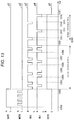
- FIG. 13 is a view illustrating each signal example in the fourth type hand operation according to the third embodiment.
- FIG. 14 is a flowchart of a process of a motor drive control unit when an instruction signal according to the third embodiment is input.
- a timepiece according to the embodiments is an electronic device such as an analog timepiece, a smart watch, and a wearable terminal which have an indicating hand.
- the timepiece is the electronic device such as the smart watch.
- FIG. 1 is a block diagram illustrating a configuration example of an electronic device 1 according to a first embodiment.
- the electronic device 1 includes a charging terminal 11 , a charging control circuit 12 , a secondary battery 13 , a switch SW, a main control unit 20 , a support body 50 , a first indicating hand 60 A, a second indicating hand 60 B, a third indicating hand 60 C, a display unit 70 , an operation unit 75 , a sensor 80 , and a buzzer 85 .
- a first indicating hand 60 A, a second indicating hand 60 B, and the third indicating hand 60 C is not specified, all of these are collectively referred to as an indicating hand 60 .
- the main control unit 20 includes a crystal oscillator 201 , an oscillator circuit 202 , a frequency divider circuit 203 , a main control circuit 204 , a display drive circuit 205 , and a communication circuit 206 .
- a load other than the indicating hand is the display drive circuit 205 and the communication circuit 206 .
- a crystal oscillator 30 , a motor drive control unit 40 , a first motor 48 A, a second motor 48 B, a third motor 48 C, a train wheel 49 A, a train wheel 49 B, and a train wheel 49 C are attached to the support body 50 .
- a motor 48 In a case where one of the first motor 48 A, the second motor 48 B, and the third motor 48 C is not specified, all of these are collectively referred to as a motor 48 .
- all of these are collectively referred to as a train wheel 49 .
- the support body 50 is detachably attached to the electronic device 1 , and is handled as a semi-finished product or an intermediate product in a case where the electronic device 1 is a finished product.
- the configuration is not limited thereto.
- the motor drive control unit 40 includes a voltage step-down circuit 41 , an input control circuit 42 , an oscillator circuit 43 , a frequency divider circuit 44 , a normal/reverse rotation determination circuit 45 (determination circuit), a drive pulse generation circuit 46 , and a drive circuit 47 .
- the normal/reverse rotation determination circuit 45 includes a normal/reverse rotation determination circuit 45 A (determination circuit), a normal/reverse rotation determination circuit 45 B (determination circuit), and a normal/reverse rotation determination circuit 45 C (determination circuit).
- the drive pulse generation circuit 46 includes a drive pulse generation circuit 46 A, a drive pulse generation circuit 46 B, and a drive pulse generation circuit 46 C.
- the drive circuit 47 includes a drive circuit 47 A, a drive circuit 47 B, and a drive circuit 47 C.
- a combination of the normal/reverse rotation determination circuit 45 A, the drive pulse generation circuit 46 A, and the drive circuit 47 A, a combination of the normal/reverse rotation determination circuit 45 B, the drive pulse generation circuit 46 B, and the drive circuit 47 B, and a combination of the normal/reverse rotation determination circuit 45 C, the drive pulse generation circuit 46 C, and the drive circuit 47 C are respectively referred to as a motor control unit.
- the first motor control unit is one of the combination of the normal/reverse rotation determination circuit 45 A, the drive pulse generation circuit 46 A, and the drive circuit 47 A, the combination of the normal/reverse rotation determination circuit 45 B, the drive pulse generation circuit 46 B, and the drive circuit 47 B, and the combination of the normal/reverse rotation determination circuit 45 C, the drive pulse generation circuit 46 C, and the drive circuit 47 C.
- the second motor control unit is a combination of a normal/reverse rotation determination circuit 45 n (n is one of A, B, and C), a drive pulse generation circuit 46 n , and a drive circuit 47 n other than the first motor control unit.
- the third motor control unit is a combination of the normal/reverse rotation determination circuit 45 n (n is one of A, B, and C), the drive pulse generation circuit 46 n , and the drive circuit 47 n other than the first motor control unit and the second motor control unit.
- the electronic device 1 presents the time by using the first indicating hand 60 A to the third indicating hand 60 C during a clocking operation.
- the electronic device 1 communicates with a terminal 90 via a wired or wireless network so as to transmit and receive information.
- the electronic device 1 transmits a detection value detected by the sensor 80 and residual quantity information indicating a residual quantity of the secondary battery 13 to the terminal 90 via the network.
- the electronic device 1 receives time information from the terminal 90 , and corrects the counted time in accordance with the received time information.
- the electronic device 1 receives an operation instruction from the terminal 90 , and controls driving of the first indicating hand 60 A to the third indicating hand 60 C in accordance with the received operation instruction.
- the terminal 90 is a device having a communication function, for example, a smartphone, a tablet terminal, a portable game machine, and a computer.
- the terminal 90 is configured to include an operation unit, a display unit, a control unit, a global positioning system (GPS), a communication unit, and a battery.
- the terminal 90 transmits time information acquired using the GPS, an operation instruction, residual quantity information of the battery of the terminal itself to the electronic device 1 via the network.
- the terminal 90 receives the detection value transmitted by the electronic device 1 , and the residual quantity information via the network, and displays the received information on the display unit.
- a circuit board 10 (substrate) (base) is a base to which the main control unit 20 and the support body 50 are attached.
- the charging terminal 11 , the charging control circuit 12 , the secondary battery 13 , the main control unit 20 , and the support body 50 are attached to the circuit board 10 .
- the charging terminal 11 receives power supply from the outside, and is a universal serial bus (USB) terminal.
- the charging terminal 11 supplies the supplied power to the charging control circuit 12 .
- the charging control circuit 12 charges the secondary battery 13 with the power supplied from the charging terminal 11 .
- the charging control circuit 12 supplies the power stored in the secondary battery 13 to the main control unit 20 and the motor drive control unit 40 attached to the support body 50 .
- the secondary battery 13 is a lithium ion polymer battery, for example.
- the main control unit 20 controls each configuration element included in the electronic device 1 .
- the main control unit 20 causes the display unit 70 to display information.
- the information to be displayed is the residual quantity of the secondary battery 13 , for example.
- the main control unit 20 acquires an operation result obtained by a user operating the operation unit 75 , and controls each configuration element included in the electronic device 1 in accordance with the acquired operation result.
- the main control unit 20 acquires the detection value output by the sensor 80 .
- the crystal oscillator 201 is a passive element used for causing a first frequency to oscillate from mechanical resonance by utilizing a piezoelectric phenomenon of quartz.
- the first frequency is 100 [MHz], for example.
- the oscillator circuit 202 realizes an oscillator in combination with the crystal oscillator 201 , and outputs a signal of the generated first frequency to the frequency divider circuit 203 .
- the frequency divider circuit 203 divides the signal of the first frequency output by the oscillator circuit 202 into a desired frequency, and outputs the divided signal to the main control circuit 204 .
- the main control circuit 204 is operated at timing of a signal output by a drive frequency, based on the first frequency.
- the main control circuit 204 is a central processing unit (CPU) for a mobile terminal or a wearable terminal, for example, and is a CPU using ARM architecture.
- the main control circuit 204 internally includes a storage unit, and stores a correspondence relationship between the instruction signal and the motor 48 (to be described later) and the definition of the instruction signal (normal rotation instruction using one instruction pulse, or the reverse rotation instruction using two instruction pulses).
- the main control circuit 204 may separately include the storage unit.
- an instruction for causing the indicating hand 60 to perform normal rotation one step via the motor 48 is referred to as a first type hand operation
- an instruction for causing the indicating hand 60 to perform reverse rotation one step via the motor 48 is referred to as a second type hand operation.
- the main control circuit 204 outputs the instruction signal for driving the motor 48 to the motor drive control unit 40 at the timing of the signal output by the frequency divider circuit 203 .
- the main control circuit 204 and the motor drive control unit 40 are connected to each other by two control lines (GATE and RDYB) and three signal lines (M 0 FR, M 1 FR, and M 2 FR).
- the main control circuit 204 controls each configuration element of the electronic device 1 , based on an operation result output by the operation unit 75 .
- the operation result is a time adjustment operation or an alarm operation.
- the main control circuit 204 causes the third indicating hand 60 C to move to a 12 o'clock position, and stops the third indicating hand 60 C.
- the main control circuit 204 controls the first indicating hand 60 A and the second indicating hand 60 B to perform a fast forwarding operation or to perform fast rewinding operation.
- the main control circuit 204 counts signals output by the frequency divider circuit 203 , and issues a signal from the buzzer 85 when the set time is up, or when the set time elapses.
- the main control circuit 204 controls a state of power supply to the motor drive control unit 40 by switching between an on-state and an off-state of the switch SW. For example, in a case where the residual quantity of the secondary battery 13 is smaller than a predetermined capacity, the main control circuit 204 may perform control so as to reduce intervals for power supply to the motor drive control unit 40 or to stop the power supply. Alternatively, the main control circuit 204 may perform control so as to reduce the intervals for power supply to the motor drive control unit 40 or to stop the power supply, based on the operation instruction received by the communication circuit 206 .
- the switch SW may be configured to include a MOS transistor.
- the main control circuit 204 controls an operation mode of the electronic device 1 , based on the operation result output by the operation unit 75 or the operation instruction received by the communication circuit 206 .
- the operation mode includes a clocking mode (normal operation mode), a chronograph mode, a time adjustment mode, an alarm setting mode, an alarm operation mode, and external control mode.
- the external control mode at least one of the first motor 48 A to the third motor 48 C is driven in response to the operation instruction output from the terminal 90 so as to operate the corresponding indicating hand.
- the main control circuit 204 may set 0% for the 12 o'clock position, 10% for the 1 o'clock position, . . . , and 100% for the 10 o'clock position, and may control the third indicating hand to present the battery residual quantity of the terminal 90 .
- the main control circuit 204 may detect the residual quantity of the secondary battery 13 .
- the main control circuit 204 may cause the display drive circuit 205 to display the detected residual quantity information of the secondary battery 13 on the display unit 70 .
- the main control circuit 204 may transmit the detected residual quantity information of the secondary battery 13 to the terminal 90 via the communication circuit 206 and the network.
- the display drive circuit 205 causes the display unit 70 to display the display information output by the main control circuit 204 .
- the display drive circuit 205 may be included in the display unit 70 .
- the communication circuit 206 transmits and receives information to and from the terminal 90 via the network in accordance with the control of the main control circuit 204 .
- the communication circuit 206 employs a communication method using the Wireless Fidelity (Wi-Fi) standard or the Bluetooth (registered trademark) Low Energy (hereinafter referred to as BLE) standard so as to transmit and receive the instruction or the information to and from the terminal 90 .
- the communication circuit 206 may acquire the information from the GPS.
- the crystal oscillator 30 is a passive element used for causing a second frequency to oscillate.
- the second frequency is lower than the first frequency, and is 32 [kHz], for example.
- the motor drive control unit 40 is operated at the timing of a signal based on the second frequency.
- the motor drive control unit 40 is a motor driver IC (integrated circuit).
- the motor drive control unit 40 determines whether a control signal output by the main control circuit 204 is a control signal for causing the motor 48 to perform normal rotation or a control signal for causing the motor 48 to perform reverse rotation. Based on the determined result, the motor drive control unit 40 generates a drive pulse, and drives the motor 48 by outputting the generated drive pulse.
- an operation for causing the indicating hand 60 to perform normal rotation one step via the motor 48 is referred to as a first operation
- an operation for causing the indicating hand 60 to perform reverse rotation one step via the motor 48 is referred to as a second operation.
- the voltage step-down circuit 41 steps down a voltage supplied from the charging control circuit 12 to 1.57 V, for example, and supplies the step-down voltage to each configuration element of the motor drive control unit 40 .
- a GATE signal is input to the input control circuit 42 .
- the input control circuit 42 outputs a signal indicating a period while the GATE signal is in an H (High) level to the normal/reverse rotation determination circuit 45 .
- the oscillator circuit 43 realizes an oscillator in combination with the crystal oscillator 30 , and outputs a signal of the generated second frequency to the frequency divider circuit 44 .
- the frequency divider circuit 44 divides a signal of the second frequency output by the oscillator circuit 43 into a desired frequency, and outputs the divided signal to the drive pulse generation circuit 46 .
- An M 0 FR signal serving as a first instruction signal is input to the normal/reverse rotation determination circuit 45 A.
- the normal/reverse rotation determination circuit 45 A counts the number of periods while the input control circuit 42 outputs a signal indicating the H-level and the number of periods while the M 0 FR signal is in the H-level. In this manner, the normal/reverse rotation determination circuit 45 A determines whether the M 0 FR signal is a normal rotation instruction signal or a reverse rotation instruction signal. The normal/reverse rotation determination circuit 45 A determines that a signal equal to or greater than a threshold value is in the H-level.
- the normal/reverse rotation determination circuit 45 A When the GATE signal is changed from the H-level to the L (low) level, the normal/reverse rotation determination circuit 45 A outputs the determination result to the drive pulse generation circuit 46 A.
- the determination result is information indicating either the normal rotation or the reverse rotation, or a signal indicating either the normal rotation or the reverse rotation.
- the H-level is set as a first level
- the L-level is set as a second level.
- An M 1 FR signal serving as a second instruction signal is input to the normal/reverse rotation determination circuit 45 B.
- the normal/reverse rotation determination circuit 45 B counts the number of periods while the input control circuit 42 outputs a signal indicating the H-level and the number of periods while the M 1 FR is in the H-level. In this manner, the normal/reverse rotation determination circuit 45 B determines whether the M 1 FR signal is the normal rotation instruction signal or the reverse rotation instruction signal.
- the normal/reverse rotation determination circuit 45 B outputs the determination result to the drive pulse generation circuit 46 B.
- An M 2 FR signal serving as a third instruction signal is input to the normal/reverse rotation determination circuit 45 C.
- the normal/reverse rotation determination circuit 45 C counts the number of periods while the input control circuit 42 outputs the signal indicating the H-level and the number of periods while the M 2 FR is in the H-level. In this manner, the normal/reverse rotation determination circuit 45 C determines whether the M 2 FR signal is the normal rotation instruction signal or the reverse rotation instruction signal.
- the normal/reverse rotation determination circuit 45 C outputs the determination result to the drive pulse generation circuit 46 C.
- the drive pulse generation circuit 46 A Based on the determination result output by the normal/reverse rotation determination circuit 45 A, the drive pulse generation circuit 46 A generates a pulse signal for causing the first motor 48 A to perform normal rotation one step or reverse rotation one step, and outputs the generated pulse signal to the drive circuit 47 A.
- the drive pulse generation circuit 46 B Based on the determination result output by the normal/reverse rotation determination circuit 45 B, the drive pulse generation circuit 46 B generates a pulse signal for causing the second motor 48 B to perform normal rotation one step or reverse rotation one step, and outputs the generated pulse signal to the drive circuit 47 B.
- the drive pulse generation circuit 46 C Based on the determination result output by the normal/reverse rotation determination circuit 45 C, the drive pulse generation circuit 46 C generates a pulse signal for causing the third motor 48 C to perform normal rotation one step or reverse rotation one step, and outputs the generated pulse signal to the drive circuit 47 C.
- the drive circuit 47 A Based on the pulse signal output by the drive pulse generation circuit 46 A, the drive circuit 47 A generates drive signals M 00 and M 01 for driving the first motor 48 A, and the first motor 48 A is driven by the generated drive signals M 00 and M 01 .
- the drive circuit 47 B Based on the pulse signal output by the drive pulse generation circuit 46 B, the drive circuit 47 B generates drive signals M 10 and M 11 for driving the second motor 48 B, and the second motor 48 B is driven by the generated drive signals M 10 and M 11 .
- the drive circuit 47 C Based on the pulse signal output by the drive pulse generation circuit 46 C, the drive circuit 47 C generates drive signals M 20 and M 21 for driving the third motor 48 C, and the third motor 48 C is driven by the generated drive signals M 20 and M 21 .
- Each of the first motor 48 A, the second motor 48 B, and the third motor 48 C is a stepping motor.
- the first motor 48 A drives the first indicating hand 60 A via the train wheel 49 A in response to the drive signals M 00 and M 01 output by the drive circuit 47 A.
- the second motor 48 B drives the second indicating hand 60 B via the train wheel 49 B in response to the drive signals M 10 and M 11 output by the drive circuit 47 B.
- the third motor 48 C drives the third indicating hand 60 C via the train wheel 49 C in response to the drive signals M 20 and M 21 output by the drive circuit 47 C.
- Each of the train wheels 49 A, 49 B, and 49 C is configured to include at least one gear.
- the first indicating hand 60 A is an hour hand, and is rotatably supported by the support body 50 .
- the second indicating hand 60 B is a minute hand, and is rotatably supported by the support body 50 .
- the third indicating hand 60 C is a second hand, and is rotatably supported by the support body 50 .
- the display unit 70 is a liquid crystal display (LCD).
- the display unit 70 displays the residual quantity information of the secondary battery 13 under the control of the main control circuit 204 .
- the display unit 70 may display an operation mode of the electronic device 1 under the control of the main control circuit 204 .
- the operation unit 75 is configured to include at least one button or crown.
- the operation unit 75 detects an operation result operated by a user, and outputs the detected operation result to the main control circuit 204 .
- the operation unit 75 may be a touch panel sensor disposed in the display unit 70 or glass on the dial.
- the operation unit 75 may detect that the buzzer 85 is tapped, and may use the detection result as an operation result.
- a signal applied to the buzzer 85 which is a piezoelectric element, is detected using the method of the invention disclosed in JP-A2014-139542, for example.
- the sensor 80 is at least one of an acceleration sensor, a geomagnetic sensor, an atmospheric pressure sensor, a temperature sensor, and an angular velocity sensor.
- the sensor 80 outputs the detection value to the main control circuit 204 .
- the main control circuit 204 uses a detection value of the acceleration sensor so as to detect the inclination of the electronic device 1 .
- the acceleration sensor is a three-axis sensor, which detects gravitational acceleration.
- the main control circuit 204 uses a detection value of the geomagnetic sensor so as to detect a direction of the electronic device 1 .
- the main control circuit 204 uses a detection value of atmospheric pressure sensor for a barometer or an altimeter.
- the main control circuit 204 uses a detection value of the angular velocity sensor (gyro sensor) so as to detect the rotation of the electronic device 1 .
- the buzzer 85 is a piezoelectric element, which issues an alarm in accordance with the control of the main control circuit 204 .
- the first frequency serving as the operation frequency of the above-described main control circuit 204 is 100 MHz, and is used for driving the load through high speed processing.
- the second frequency serving as the operation frequency of the motor drive control unit 40 is 32 kHz.
- 7.5 ms interval drive of BLE is 133 Hz.
- the drive frequency of the motor drive control unit 40 is 32 Hz for fast forwarding drive of the indicating hand, and second hand operation drive is 1 Hz.
- the operation frequency represents the operation frequency (clock frequency) supplied from the frequency divider circuit 203 to the main control circuit 204 , and the operation frequency (clock frequency) supplied from the crystal oscillator 30 to the motor drive control unit 40 .
- the operation frequency is different from a drive frequency (frequency for driving) which drives the motor serving as a driven unit.
- the clock signal forming a basis of the first frequency generated by the oscillation of the oscillator circuit 202 and the clock signal forming a basis of the second frequency generated by oscillation of the oscillator circuit 43 are asynchronous with each other.
- control line and the signal line will be described.
- the two control lines are GATE and RDYB, and the three signal lines are M 0 FR, M 1 FR, and M 2 FR.
- the control line GATE is the control line through which the main control circuit 204 outputs the GATE signal, and the GATE signal indicates a boundary of timing to output the instruction signals (M 0 FR, M 1 FR, and M 2 FR) to each motor 48 .
- the GATE signal is a timing definition signal which defines (defines, or demarcates, or delimits) the drive timing of each the motor 48 by distinguishing the drive timing of each motor 48 from other timing.
- the signal line M 0 FR is the signal line through which the main control circuit 204 outputs the M 0 FR signal serving as the first instruction signal, and is the instruction signal which causes the first motor 48 A to perform normal rotation or reverse rotation.
- the signal line M 1 FR is the signal line through which the main control circuit 204 outputs the M 1 FR signal serving as the second instruction signal, and is the instruction signal which causes the second motor 48 B to perform normal rotation or reverse rotation.
- the signal line M 2 FR is the signal line through which the main control circuit 204 outputs the M 2 FR signal serving as the third instruction signal and is the instruction signal which causes the third motor 48 C to perform normal rotation or reverse rotation.
- the control line RDYB is the control line through which the motor drive control unit 40 outputs the RDYB signal, and is a signal indicating a period during which the motor drive control unit 40 performs the instruction.
- the motor drive control unit 40 may include the normal/reverse rotation determination circuits 45 A and 45 B, the drive pulse generation circuits 46 A and 46 B, and the drive circuits 47 A and 47 B.
- the main control circuit 204 and the motor drive control unit 40 may be connected to each other by two control lines (GATE and RDYB) and two signal lines (M 0 FR and M 1 FR).
- the motor drive control unit 40 may include the normal/reverse rotation determination circuit 45 A, the drive pulse generation circuit 46 A, and the drive circuit 47 A.
- the main control circuit 204 and the motor drive control unit 40 may be connected to each other by two control lines (GATE and RDYB) and one signal line (M 0 FR).
- the charging terminal 11 , the charging control circuit 12 , the secondary battery 13 , the main control unit 20 , and the support body 50 are arranged on the circuit board 10 .
- the arrangement example illustrated in FIG. 2 is merely an example, and the arrangement on the circuit board 10 in the electronic device 1 is not limited thereto.
- FIG. 2 is a view illustrating an example in which the charging terminal 11 , the charging control circuit 12 , the secondary battery 13 , the main control unit 20 , and the support body 50 are arranged on the circuit board 10 according to the present embodiment.
- a position A to a position D around the timepiece centered on a line AB are respectively referred to as a 12 o'clock position, a 3 o'clock position, a 6 o'clock position, and a 9 o'clock position.
- the support body 50 is disposed substantially at the center
- the main control unit 20 is disposed approximately at the 9 o'clock position
- the display unit 70 is disposed approximately at the 11 o'clock position.
- the main control circuit 204 and the motor drive control unit 40 are connected to each other by two control lines (GATE and RDYB) and three signal lines (M 0 FR, M 1 FR, and M 2 FR) as indicated by the reference numeral 501 .
- the support body 50 includes a connector 511 , and the main control circuit 204 and five signal lines are connected to the connector 511 .
- the connector 511 and the motor drive control unit 40 are connected to each other by a wiring material disposed on the support body 50 .
- operation units 75 A to 75 C are arranged approximately at the 2 o'clock to 4 o'clock positions on the right side of the circuit board 10 .
- the secondary battery 13 is disposed approximately at the 7 o'clock position on the lower left side of the circuit board 10 .
- the charging control circuit 12 and the charging terminal 11 are arranged approximately at the 8 o'clock position.
- the motor drive control unit 40 the first motor 48 A, the second motor 48 B, the third motor 48 C, the train wheel 49 A, the train wheel 49 B, and the train wheel 49 C are attached onto the support body 50 .
- the first indicating hand 60 A, the second indicating hand 60 B, and the third indicating hand 60 C are attached to the support body 50 .
- FIGS. 1 and 2 an example has been described in which three sets of motor control unit (the normal/reverse rotation determination circuit, the drive pulse generation circuit, and the drive circuit) and three motors 48 are arranged on the support body 50 .
- the configuration is not limited thereto.
- the first support body 50 may include the crystal oscillator 30 , the voltage step-down circuit 41 , the input control circuit 42 , the oscillator circuit 43 , the frequency divider circuit 44 , two sets of motor control unit (the normal/reverse rotation determination circuits 45 A and 45 B, the drive pulse generation circuits 46 A and 46 B, and the drive circuits 47 A and 47 B).
- the second support body 50 may include the crystal oscillator 30 , the voltage step-down circuit 41 , the input control circuit 42 , the oscillator circuit 43 , the frequency divider circuit 44 , one set of motor control unit (the normal/reverse rotation determination circuit 45 C, the drive pulse generation circuit 46 C, and the drive circuit 47 C).
- the main control circuit 204 and the first support body may be connected to each other by two control lines (GATE and RDYB) and two signal lines (M 0 FR and M 1 FR).
- the main control circuit 204 and the second support body may be connected to each other by two control lines (GATE and RDYB) and one signal line (M 2 FR).
- the total number of the control lines and the signal lines between the main control circuit 204 and the support body 50 is five. According to this configuration, the indicating hand is more freely disposed on the dial (not illustrated).
- FIG. 3 is a view illustrating an example of the timing of the GATE signal, the instruction signal (M 0 FR), the drive pulse, and the RDYB signal according to the present embodiment.
- the horizontal axis represents the time
- the vertical axis represents whether each signal is in an H-level or in an L-level.
- a waveform g 1 is a signal waveform of the GATE signal
- a waveform g 2 is a signal waveform of the M 0 FR signal
- a waveform g 3 is the signal waveform of the drive signal M 00
- a waveform g 4 is a signal waveform of the drive signal M 01
- a waveform g 5 is a signal waveform of the RDYB signal.
- a period of times t 1 to t 10 is an example in which the motor 48 is caused to perform normal rotation
- a period of times t 11 to t 28 is an example in which the motor 48 is caused to perform reverse rotation.
- the main control circuit 204 changes the GATE signal from the L-level to the H-level at time t 1 . Subsequently, the main control circuit 204 changes the M 0 FR signal from the L-level to the H-level at time t 2 , and changes the M 0 FR signal from the H-level to the L-level at time t 3 . A period (times t 2 to t 3 ) during which the M 0 FR signal is in the H-level is 10 [ns], for example. Subsequently, the main control circuit 204 changes the GATE signal from the H-level to the L-level at time t 4 . A period (times t 1 to t 4 ) during which the GATE signal is in the H-level is 30 [ns], for example.
- the normal/reverse rotation determination circuit 45 A determines that the signal indicates the instruction for normal rotation of the motor 48 . Subsequently, the drive circuit 47 A changes the drive signal M 00 from the H-level to the L-level at time t 4 , and changes the drive signal M 00 from the L-level to the H-level at time t 5 . Based on the output of the normal/reverse rotation determination circuit 45 A and the drive circuit 47 A, the motor drive control unit 40 sets the RDYB signal to be in the H-level in a period of times t 4 to t 5 . The period of times t 4 to t 5 during which the drive signal M 00 is in the L-level is 5 to 6 [ms], for example.
- the main control circuit 204 controls the GATE signal and the M 0 FR signal, similarly to the period of times t 6 to t 9 and the period of times t 1 to t 4 .
- the normal/reverse rotation determination circuit 45 A determines that the signal indicates the instruction for normal rotation of the motor 48 . Subsequently, the drive circuit 47 A changes the drive signal M 01 from the H-level to the L-level at time t 9 , and changes the drive signal M 01 from the L-level to the H-level at time t 10 . Based on the output of the normal/reverse rotation determination circuit 45 A and the drive circuit 47 A, the motor drive control unit 40 sets the RDYB signal to be in the H-level in a period of times t 9 to t 10 . The period of times t 9 to t 10 during which the drive signal M 01 is in the L-level is 5 to 6 [ms], for example.
- the main control circuit 204 changes the GATE signal from the L-level to the H-level at time t 11 . Subsequently, the main control circuit 204 changes the M 0 FR signal from the L-level to the H-level at time t 12 , changes the M 0 FR signal from the H-level to the L-level at time t 13 , changes the M 0 FR signal from the L-level to the H-level at time t 14 , and changes the M 0 FR signal from the H-level to the L-level at time t 15 . Subsequently, the main control circuit 204 changes the GATE signal from the H-level to the L-level at time t 16 . A period (times t 11 to t 16 ) during which the GATE signal is in the H-level is 50 [ns], for example.
- the normal/reverse rotation determination circuit 45 A determines that the signal indicates the instruction for reverse rotation of the motor 48 . Subsequently, the drive circuit 47 A changes the drive signal M 00 from the H-level to the L-level at time t 16 . Subsequently, the drive circuit 47 A changes the drive signal M 00 from the L-level to the H-level at time t 17 , and changes the drive signal M 01 from the H-level to the L-level.
- the drive circuit 47 A changes the drive signal M 00 from the H-level to the L-level at time t 18 , and changes the drive signal M 01 from the L-level to the H-level. Subsequently, the drive circuit 47 A changes the drive signal M 00 from the L-level to the H-level at time t 19 . Based on the output of the normal/reverse rotation determination circuit 45 A and the drive circuit 47 A, the motor drive control unit 40 sets the RDYB signal to be in the H-level in a period of times t 16 to t 19 .
- the main control circuit 204 controls the GATE signal and the M 0 FR signal, similarly to the period of times t 20 to t 25 and the period of times t 11 to t 16 .
- the normal/reverse rotation determination circuit 45 A determines that the signal indicates the instruction for reverse rotation of the motor 48 . Subsequently, the drive circuit 47 A changes the drive signal M 01 from the H-level to the L-level at time t 25 . Subsequently, the drive circuit 47 A changes the drive signal M 00 from the H-level to the L-level at time t 26 , and changes the drive signal M 01 from the L-level to the H-level.
- the drive circuit 47 A changes the drive signal M 00 from the L-level to the H-level at time t 27 , and changes the drive signal M 01 from the H-level to the L-level. Subsequently, the drive circuit 47 A changes the drive signal M 01 from the L-level to the H-level at time t 28 . Based on the output of the normal/reverse rotation determination circuit 45 A and the drive circuit 47 A, the motor drive control unit 40 sets the RDYB signal to be in the H-level in a period of times t 25 to t 28 .
- each period during which the M 0 FR signal is in the H-level (second level) is referred to as an instruction signal.
- each period of time t 2 to time t 3 , time t 7 to time t 8 , time t 12 to time t 13 , time t 14 to time t 15 , time t 21 to time t 22 , and time t 23 to time t 24 is an instruction pulse. Therefore, in a period of time t 1 to time t 5 during which the GATE signal serving as a timing definition signal is in the H-level, the number of instruction pulses is one. In a period of time t 11 to time t 16 during which the GATE signal serving as a timing definition signal is in the H-level, the number of instruction pulses is two.
- FIG. 3 illustrates an example of the M 0 FR signal
- a relationship among the GATE signal, the M 1 FR signal, and the drive signals M 10 and M 11 is the same as above
- a relationship among the GATE signal, the M 2 FR signal, and the drive signals M 20 and M 21 is also the same as above.
- an example has been described in which normal rotation is performed when there is one instruction pulse of the instruction signal and reverse rotation is performed when there are two instruction pulses.
- the configuration is not limited thereto.
- An operation corresponding to the number of instruction pulses may be determined in advance by the main control circuit 204 and the motor drive control unit 40 .
- the number of instruction pulses may be three or more.
- the operation corresponding to the number of instruction pulses may be stored in advance in the main control circuit 204 and the motor drive control unit 40 .
- the main control circuit 204 may control a plurality of motors 48 at the same time. In this case, for example, in a period during which the GATE signal is in the H-level, the main control circuit 204 changes the M 0 FR signal and the M 1 FR signal to each H-level and L-level of the M 2 FR signal.
- the motor drive control unit 40 to which the instruction signal is input may control the first motor 48 A to perform normal rotation, the second motor 48 B to perform reverse rotation, and the third motor 48 C to perform normal rotation.
- FIG. 4 is a view illustrating an example of the timing of the GATE signal, the instruction signals (M 0 FR and M 1 FR), the drive pulse, and the RDYB signal according to the present embodiment.
- the horizontal axis represents the time
- the vertical axis represents whether each signal is in the H-level or in the L-level.
- the waveforms g 1 to g 5 are the same as those in FIG. 3 .
- a waveform g 6 is a signal waveform of the M 1 FR signal
- a waveform g 7 is a signal waveform of the drive signal M 10
- a waveform g 8 is a signal waveform of the drive signal M 11 .
- the main control circuit 204 changes the GATE signal from the L-level to the H-level at time t 31 . Subsequently, the main control circuit 204 changes each of the M 0 FR signal and the M 1 FR signal from the L-level to the H-level at time t 32 , and changes the M 0 FR signal and the M 1 FR signal from H-level to the L-level at time t 33 . Subsequently, the main control circuit 204 changes the GATE signal from the H-level to the L-level at time t 34 .
- the normal/reverse rotation determination circuit 45 A determines that the signal indicates the instruction for normal rotation of the motor 48 . Subsequently, the drive circuit 47 A changes the drive signal M 00 from the H-level to the L-level at time t 34 , and changes the drive signal M 00 from the L-level to the H-level at time t 35 .
- the normal/reverse rotation determination circuit 45 B determines that the signal indicates the instruction for normal rotation of the motor 48 . Subsequently, the drive circuit 47 B changes the drive signal M 10 from the H-level to the L-level at time t 34 , and changes the drive signal M 10 from the L-level to the H-level at time t 35 .
- the motor drive control unit 40 sets the RDYB signal to be in the H-level in a period of times t 34 to t 35 .
- the main control circuit 204 controls the GATE signal, the M 0 FR signal, and the M 1 FR signal.
- the drive circuit 47 A changes the drive signal M 01 from the H-level to the L-level at time t 39 , and changes the drive signal M 01 from the L-level to the H-level at time t 40 .
- the drive circuit 47 B changes the drive signal M 11 from the H-level to the L-level at time t 39 , and changes the drive signal M 11 from the L-level to the H-level at time t 40 .
- the motor drive control unit 40 sets the RDYB signal to be in the H-level in a period of times t 39 to t 40 .
- FIG. 5 is a view for describing the operation period of the main control circuit 204 according to the present embodiment.
- the horizontal axis represents the time, and the vertical axis represents whether each signal is in the H-level or in the L-level.
- a waveform g 11 indicates the drive signal M 00
- a waveform g 12 indicates the drive signal M 01
- a waveform g 13 indicates an operation period of a main control circuit according to a comparative example which does not employ the GATE signal.
- a waveform g 14 indicates the operation period of the main control circuit 204 according to the present embodiment which employs the GATE signal.
- the example illustrated in FIG. 5 shows an example in a case where the motor 48 is caused to perform normal rotation.
- a region enclosed by g 10 is an example of the waveform of the GATE signal and the M 0 FR signal in a period of times t 101 to t 102 of the waveform g 14 .
- the period of the M 0 FR signal in a case where the motor 48 is caused to perform normal rotation is 10 [ns]
- the period of the GATE signal is 30 [ns]. This time shows a case where the oscillation frequency of the crystal oscillator 201 is 100 [MHz].
- the main control circuit 204 is operated in the period during which the GATE signal is in the H-level, that is, in 30 [ns].
- the main control circuit needs to be continuously operated in a period of times t 102 to t 103 during which the drive pulse is supplied to the motor 48 .
- the period of times t 102 to t 103 for the normal rotation of the motor 48 is 6 [ms], for example.
- power consumption of the main control circuit 204 while the motor is driven for normal rotation can be reduced to 1/200.
- FIG. 6 is a flowchart of a process when the main control circuit 204 according to the present embodiment outputs the instruction signal.
- the main control circuit 204 performs the following process at every one clock of 10 [ns] by using 100 [MHz].
- Step S 1 The main control circuit 204 sets the GATE signal to be output to the GATE control line to be in the H-level.
- Step S 2 The main control circuit 204 sets the MmFR signal to be output to the MmFR signal line (m is an integer of 0, 1, and 2) to be in the H-level.
- Step S 3 The main control circuit 204 sets the MmFR signal output to the MmFR signal line (m is an integer of 0, 1, and 2) to be in the L-level.
- Step S 4 The main control circuit 204 sets the GATE signal to be output to the GATE control line to be in the L-level.
- FIG. 7 is a flowchart of a process of the motor drive control unit 40 when the instruction signal according to the present embodiment is input.
- the motor drive control unit 40 performs the following process, based on a clock of 32 [kHz], for example.
- Step S 11 The input control circuit 42 detects a period during which the GATE signal to be input to the GATE control line is in the H-level. Subsequently, the input control circuit 42 detects that the GATE signal is changed from the H-level to the L-level.
- Step S 12 The normal/reverse rotation determination circuit 45 counts the number of instruction pulses in the H-level of the MmFR signal in a period during which the GATE signal is in the H-level. Based on the number of counted instruction pulses, the normal/reverse rotation determination circuit 45 determines whether the instruction is a normal rotation instruction or a reverse rotation instruction.
- Step S 13 Based on the determination result output by the normal/reverse rotation determination circuit 45 , the drive pulse generation unit 46 generates a pulse signal for causing the motor 48 to perform normal rotation one step or reverse rotation one step.
- Step S 14 Based on the pulse signal output by the drive pulse generation circuit 46 , the drive circuit 47 generates a drive signal for driving the motor 48 , and drives the motor 48 by using the generated drive signal.
- FIG. 8 is a flow chart of the process of the main control circuit without employing the GATE signal according to the comparative example. Similarly to FIG. 6 , the main control circuit performs the following process at every one clock of 10 [ns] by using 100 [MHz], for example.
- Step S 901 The main control circuit sets the MmFR signal to be output to the MmFR signal line to be in the H-level. Subsequently, the main control circuit starts a counter.
- Step S 902 The main control circuit determines whether or not 6 [ms] elapse, based on a measured value of the counter. In a case where the main control circuit determines that 6 [ms] do not elapse (Step S 902 ; NO), the process in Step S 902 is repeated. In a case where the main control circuit determines that 6 [ms] elapse (Step S 902 ; YES), the process proceeds to Step S 903 .
- Step S 903 The main control circuit sets the MmFR signal to be output to the MmFR signal line to be in the L-level.
- the main control circuit is continuously operated for 6 [ms] during which the motor 48 is driven, thereby consuming power.
- the main control circuit 204 is operated only for the period of 40 [ns] during which the GATE signal is in the H-level. Accordingly, compared to the comparative example, power consumption can be reduced.
- the number of H-levels of the MmFR (m is an integer of 0, 1, or 2) in the period during which the GATE signal is in the H-level is counted.
- the drive pulse is generated by determining whether the instruction is the normal rotation instruction or the reverse rotation instruction.
- the main control circuit 204 and the motor drive control unit 40 can be connected to each other by two control lines and three signal lines, the number of which is the same as the number of motors 48 .
- the RDYB signal indicates the period during which the motor drive control unit 40 drives the motor 48 and the instruction is not received.
- the instruction may not be transmitted for a predetermined time required for driving the motor 48 .
- the main control circuit 204 and the motor drive control unit 40 may be connected to each other by one control line and three signal lines excluding the RDYB control line.
- one motor 48 is provided with one signal line (M 0 FR, M 1 FR, or M 2 FR) controlling each motor 48 , and is further provided with the control line of the GATE signal. Therefore, the number of inputs to the motor drive control unit 40 included in the electronic device 1 according to the present embodiment is obtained by adding one to the number of motors.
- the instruction signal (any one of the M 0 FR signal, the M 1 FR signal, and the M 2 FR signal) for instructing the timing to drive the motor 48 (any one of the first motor 48 A to the third motor 48 C) according to the present embodiment has one instruction pulse in the period during which the GATE signal is continuously in the H-level at the time of normal rotation, and has two instruction pulses at the time of reverse rotation.
- power consumption of the main control circuit 204 when the motor is driven to perform normal rotation can be reduced to 1/200.
- the electronic device 1 includes the charging terminal 11 , the charging control circuit 12 , and the secondary battery 13 .
- an electronic device 1 A includes a solar cell and a secondary battery.
- the H-level is referred to as a first level
- the L-level is referred to as a second level.
- FIG. 9 is a block diagram illustrating a configuration example of the electronic device 1 A according to the present embodiment.
- the same reference numerals will be used for configuration elements having the same functions as those of the electronic device 1 ( FIG. 1 ) described in the first embodiment.
- the electronic device 1 A includes a solar cell G, a diode D, a secondary battery E, a switch SW, a main control unit 20 A, the support body 50 , the first indicating hand 60 A, the second indicating hand 60 B, the third indicating hand 60 C, the display unit 70 , the operation unit 75 , the sensor 80 , and the buzzer 85 .
- the solar cell G, the diode D, the secondary battery E, the main control unit 20 A, and the support body 50 are attached to a circuit board 10 A.
- the main control unit 20 A includes the crystal oscillator 201 , the oscillator circuit 202 , the frequency divider circuit 203 , the main control circuit 204 , the display drive circuit 205 , the communication circuit 206 , the charging control circuit 207 , and the power supply circuit 208 .
- the solar cell G is a solar panel.
- the solar cell G converts light energy into power, and supplies the converted power to the secondary battery E and the main control unit 20 A.
- the diode D is inserted between the solar cell G and the secondary battery E in order to prevent reverse flowing from the secondary battery E to the solar cell G.
- the secondary battery E is a storage battery for storing electric energy supplied from the solar cell G.
- the secondary battery E supplies the stored power to the main control unit 20 A.
- the charging control circuit 207 controls the secondary battery E charged with the power generated by the solar cell G.
- the charging control circuit 207 detects a charging voltage of the secondary battery E. In a case where the charging voltage of the secondary battery E is detected and the detected charging voltage is equal to or greater than a predetermined threshold value, the charging control circuit 207 performs control so that a current does not flow from the solar cell G to the secondary battery E, thereby preventing the overcharge.
- the power supply circuit 208 is configured to include a voltage step-down circuit, an oscillation constant voltage circuit, a logic constant voltage circuit, and a power supply boosting circuit.
- the voltage step-down circuit steps down the voltage of the power generated by the solar cell G and the power stored in the secondary battery E to a desired voltage value, and supplies the power having the stepped down voltage value to the oscillation constant voltage circuit, the logic constant voltage circuit, and the power supply boosting circuit.
- the oscillation constant voltage circuit uses the power supplied from the voltage step-down circuit so as to generate a constant voltage to be supplied to the oscillator circuit 202 , and supplies the generated constant voltage to the oscillator circuit 202 .
- the logic constant voltage circuit generates a constant voltage to be supplied to a logic unit by using the power supplied from the voltage step-down circuit, and supplies the generated constant voltage to the logic unit.
- the logic unit includes at least the main control circuit 204 .
- the power supply boosting circuit boosts the power supplied from the voltage step-down circuit to a desired voltage value, and supplies the power having the boosted voltage value to the display drive circuit 205 .
- the main control unit 20 A may include a power generation amount detection circuit for detecting a power generation amount of the solar cell G, a luminance detection circuit for detecting the luminance of the environment in which the electronic device 1 is used, and a battery residual quantity detection circuit for detecting the battery residual quantity of the secondary battery E. Each detection circuit may output the detection value to the main control circuit 204 .
- the main control circuit 204 and the motor drive control unit 40 are also connected to each other by two control lines and three signal lines. Therefore, the electronic device 1 A according to the present embodiment can also obtain an advantageous effect the same as that according to the first embodiment.
- a motor driver is included in the main control unit.
- the motor drive control unit 40 is separated from the main control circuit 204 . In this manner, according to the above-described embodiments, a process load is reduced in the main control circuit 204 , thereby improving self-controllability on the motor drive control unit 40 side.
- the signal line for transmitting the control signal from the main control circuit 204 to the motor drive control unit 40 employs a single line. In this manner, it is possible to minimize the number of signal lines allocated to motor control in the main control circuit 204 .
- the control line to the motor drive control unit 40 can be ensured. Therefore, the motor 48 can be reliably driven and controlled.
- the operation time of the main control circuit 204 when the indicating hand is driven is most shortened. Accordingly, the power of the main control circuit 204 can be saved.
- a configuration is adopted in which the RDYB signal indicating a hand operating state is output. Accordingly, until the main control circuit 204 outputs the subsequent instruction signal (hand operation control signal), the timepiece waits for edge interrupt. Therefore, the power of the main control circuit 204 can also be saved during high speed hand operation.
- the motor drive control unit 40 is operated, for example, with current consumption of approximately 0.1 ⁇ A during a period other than the hand operation time, thereby minimizing a contribution ratio to the power consumption of the entire system.
- the input period of the instruction signal is defined by the GATE signal, and the input period is minimized. Accordingly, an erroneous operation against external noise can be prevented.
- the motor drive control unit 40 is operated by stepping down the power supply voltage of the motor drive control unit 40 to the same voltage (1.57 V, for example) as that of the indicating hand electronic timepiece in the related art. Accordingly, even if the power supply voltage of the whole system is 3 V to 4.2 V as in a lithium ion battery, the specification of the motor 48 can achieve power saving or can achieve optimized high torques.
- the hand positions are managed by the main control circuit 204 . Accordingly, a hand position counter inside the motor drive control unit 40 is not needed, and thus, the circuit scale can be minimized.
- the configuration is not limited thereto.
- the power consumption may correspond to a logic circuit of the main control circuit 204 to be used.
- the main control circuit 204 may switch the GATE signal from the H-level to the L-level at time t 3 in FIG.
- the M 0 FR signal from the H-level to the L-level at time t 2 may switch the M 0 FR signal from the L-level to the H-level at time t 3 , and may switch the GATE signal from the L-level to the H-level at the time t 4 .
- the first level is the L-level
- the second level is the H-level.
- the main control circuit 204 outputs two types of instruction (instruction to cause the motor 48 to perform normal rotation, instruction to cause the motor 48 to perform reverse rotation) to the motor drive control unit 40 .
- instruction to cause the motor 48 to perform normal rotation instruction to cause the motor 48 to perform reverse rotation
- the configuration is not limited thereto.
- the number of instruction types may be three or more.
- FIG. 10 is a block diagram illustrating a configuration example of an electronic device 1 B according to the present embodiment.
- the electronic device 1 B includes the charging terminal 11 , the charging control circuit 12 , the secondary battery 13 , the switch SW, a main control unit 20 B, a support body 50 B, the first indicating hand 60 A, the second indicating hand 60 B, the third indicating hand 60 C, the display unit 70 , the operation unit 75 , the sensor 80 , and the buzzer 85 .
- the same reference numerals will be used for configuration elements having the same functions as those of the electronic device 1 ( FIG. 1 ) described in the first embodiment.
- FIG. 10 an example will be described in which the present embodiment is applied to the electronic device 1 . However, it is also possible to apply the present embodiment to the configuration of the electronic device 1 A ( FIG. 9 ).
- the main control unit 20 B includes the crystal oscillator 201 , the oscillator circuit 202 , the frequency divider circuit 203 , a main control circuit 204 B, the display drive circuit 205 , and the communication circuit 206 .
- the crystal oscillator 30 , the motor drive control unit 40 B, the first motor 48 A, the second motor 48 B, the third motor 48 C, the train wheel 49 A, the train wheel 49 B, and the train wheel 49 C are attached to the support body 50 B.
- the motor drive control unit 40 B includes the voltage step-down circuit 41 , the input control circuit 42 , the oscillator circuit 43 , the frequency divider circuit 44 , a hand operation classification determination circuit 451 (determination circuit), the drive pulse generation circuit 46 , and the drive circuit 47 .
- the hand operation classification determination circuit 451 includes a hand operation classification determination circuit 451 A (determination circuit), a hand operation classification determination circuit 451 B (determination circuit), and a hand operation classification determination circuit 451 C (determination circuit).
- the main control circuit 204 B outputs an instruction to operate the indicating hand 60 using a third type (hereinafter, referred to as a third type hand operation), and an instruction to operate the indicating hand 60 using a fourth type (hereinafter, referred to as a fourth type hand operation) to the motor drive control unit 40 B.
- a third type hand operation an instruction to operate the indicating hand 60 using a third type
- a fourth type hand operation an instruction to operate the indicating hand 60 using a fourth type (hereinafter, referred to as a fourth type hand operation) to the motor drive control unit 40 B.
- an operation for causing the indicating hand 60 to perform normal rotation via the motor 48 is referred to as a first operation
- an operation for causing the indicating hand 60 to perform reverse rotation via the motor 48 is referred to as a second operation
- an operation for causing the indicating hand 60 to be operated using the third type via the motor 48 is referred to as a third operation
- an operation for causing the indicating hand 60 to be operated using the fourth type via the motor 48 is referred to as a fourth operation.
- the hand operation classification determination circuit 451 determines a type of the instruction signal output by the main control circuit 204 B.
- the hand operation classification determination circuit 451 outputs the determination result to the drive pulse generation circuit 46 .
- the M 0 FR signal serving as the first instruction signal is input to the hand operation classification determination circuit 451 A.
- the hand operation classification determination circuit 451 A counts the number of periods during which the input control circuit 42 outputs the signal indicating the H-level and the number of periods during which the M 0 FR signal is in the H-level, thereby identifying hand operation classification of the M 0 FR signal.
- the hand operation classification determination circuit 451 A outputs the determination result to the drive pulse generation circuit 46 A, when the GATE signal is changed from the H-level to the L-level.
- the determination result indicates any one of information or a signal indicating normal rotation, information or a signal indicating reverse rotation, information or a signal indicating a low voltage hand operation (also referred to as BLI (abbreviation of a battery life indicator) hand operation), and information or a signal indicating a demonstration hand operation.
- the low-voltage hand operation is a hand operation of the indicating hand in a state where the voltage value of the secondary battery 13 is equal to or smaller than a predetermined voltage.
- the low-voltage hand operation means a state where the indicating hand is operated two steps once every 2 seconds.
- the demonstration hand operation means a hand operation state used for confirmation of the operation or demonstration when the timepiece is shipped or displayed at stores.
- the demonstration hand operation means a hand operation state where each indicating hand 60 performs normal rotation to reverse rotation or performs reverse rotation to normal rotation.
- the M 1 FR signal serving as the second instruction signal is input to the hand operation classification determination circuit 451 B.
- the hand operation classification determination circuit 451 B counts the number of periods during which the input control circuit 42 outputs the signal indicating the H-level, and the number of periods during which the M 1 FR signal is in the H-level, thereby identifying the hand operation classification of the M 1 FR signal.
- the hand operation classification determination circuit 451 B outputs the determination result to the drive pulse generation circuit 46 B.
- the M 2 FR signal serving as the third instruction signal is input to the hand operation classification determination circuit 451 C.
- the hand operation classification determination circuit 451 C counts the number of periods during which the input control circuit 42 outputs a signal indicating the H-level, and the number of periods during which the M 2 FR signal is in the H-level, thereby identifying the hand operation classification of the M 2 FR signal.
- the hand operation classification determination circuit 451 C outputs the determination result to the drive pulse generation circuit 46 C.
- FIG. 11 is a view illustrating an example of each instruction signal of the first type hand operation to the fourth type hand operation according to the present embodiment.
- the instruction signal description will be made using the M 0 FR signal.
- the horizontal axis represents the time, and the vertical axis represents whether each signal is in the H-level or in the L-level.
- the waveform g 1 is a signal waveform of the GATE signal
- the waveform g 2 is a signal waveform of the M 0 FR signal.
- a period of time t 201 to time t 202 has one instruction pulse of the instruction signal, and represents a period of the first type hand operation which causes the indicating hand 60 to perform the normal rotation hand operation.
- a period of time t 203 to time t 204 has two instruction pulses of the instruction signal, and represents a period of the second type hand operation which causes the indicating hand 60 to perform the reverse rotation hand operation.
- a period of time t 205 to time t 206 has three instruction pulses of the instruction signal, and represents a period of the third type hand operation which causes the indicating hand 60 to perform the low voltage hand operation.
- a period of time t 207 to time t 208 has four instruction pulses of the instruction signal, and represents a period of the fourth type hand operation which causes the indicating hand 60 to perform the demonstration hand operation.
- FIG. 12 is a view illustrating each signal example in the third type hand operation according to the present embodiment.
- the horizontal axis represents the time, and the vertical axis represents whether each signal is in the H-level or in the L-level.
- the waveforms g 1 to g 5 are the same as those in FIG. 3 .
- the M 0 FR signal indicates an example of the instruction signal.
- the main control circuit 204 B changes the GATE signal from the L-level to the H-level in a period of time t 251 to time t 252 . Subsequently, the main control circuit 204 B outputs three instruction pulses in which the M 0 FR signal is in the H-level in the period of time t 251 to time t 252 .
- the hand operation classification determination circuit 451 A determines the instruction for the low voltage hand operation. Subsequently, the drive circuit 47 A changes the drive signal M 00 from the H-level to the L-level at time t 252 , and changes the drive signal M 00 from the L-level to the H-level at time t 253 . Based on the output of the hand operation classification determination circuit 451 A and the drive circuit 47 A, the motor drive control unit 40 B sets the RDYB signal to be in the H-level at time t 252 .
- the drive circuit 47 A changes the drive signal M 01 from the H-level to the L-level at time t 254 , and changes the drive signal M 01 from the L-level to the H-level at time t 255 .
- the motor drive control unit 40 B sets the RDYB signal to be in the L-level at time t 255 . In this manner, the first indicating hand 60 A performs normal rotation for two steps.
- An operation in a period time t 256 to time t 260 is similar to an operation of a period of time t 251 to time t 255 .
- a period of time t 251 and time t 256 is 2 seconds, for example.
- a period of time t 252 and time t 254 is 125 ms, for example.
- FIG. 13 is a view illustrating each signal example in the fourth type hand operation according to the present embodiment.
- the horizontal axis represents the time
- the vertical axis represents whether each signal is in the H-level or in the L-level.
- the waveforms g 1 to g 5 are the same as those in FIG. 12 .
- FIG. 13 illustrates an example in which the M 0 FR signal is the instruction signal. In the example illustrated in FIG. 13 , as the demonstration hand operation, normal rotation is performed four times after reverse rotation is performed four times.
- the main control circuit 204 B changes the GATE signal from the L-level to the H-level in a period of time t 301 to time t 302 . Subsequently, the main control circuit 204 B outputs four instruction pulses in which the M 0 FR signal is in the H-level in the period of time t 301 to time t 302 .
- the hand operation classification determination circuit 451 A determines the instruction for demonstration hand operation. Subsequently, the drive circuit 47 A outputs the drive signal M 00 and the drive signal M 01 so that the first indicating hand 60 A performs reverse rotation four times in a period of time t 302 to time t 309 . Subsequently, the drive circuit 47 A outputs the drive signal M 00 and the drive signal M 01 so that the first indicating hand 60 A performs normal rotation four times in a period of time t 310 to time t 317 . Based on the output of the hand operation classification determination circuit 451 A and the drive circuit 47 A, the motor drive control unit 40 B sets the RDYB signal to be in the H-level in a period of time t 302 to t 317 .
- FIG. 14 is a flowchart of a process of the motor drive control unit 40 B when the instruction signal according to the present embodiment is input.
- Step S 101 The input control circuit 42 detects a period during which the GATE signal input to the GATE control line is in the H-level. Subsequently, the input control circuit 42 detects that the GATE signal is changed from the H-level to the L-level.
- Step S 102 The hand operation classification determination circuit 451 counts the number of instruction pulses in which the MmFR signal is in the H-level in a period during which the GATE signal is in the H-level, and determines a type of the instruction signal, based on the number of counted instruction pulses. In a case where the hand operation classification determination circuit 451 determines the first type hand operation, the process proceeds to Step S 103 . In a case where the hand operation classification determination circuit 451 determines the second type hand operation, the process proceeds to Step S 104 . In a case where the hand operation classification determination circuit 451 determines the third type hand operation, the process proceeds to Step S 105 . In a case where the hand operation classification determination circuit 451 determines the fourth type hand operation, the process proceeds to Step S 106 .
- Step S 103 Based on the determination result output by the hand operation classification determination circuit 451 , the drive pulse generation unit 46 generates the pulse signal for causing the motor to perform normal rotation one step (first type hand operation). After the process is performed by the drive pulse generation unit 46 , the process proceeds to Step S 107 .
- Step S 104 Based on the determination result output by the hand operation classification determination circuit 451 , the drive pulse generation unit 46 generates the pulse signal for causing the motor to perform reverse rotation one step (second type hand operation). After the process is performed by the drive pulse generation unit 46 , the process proceeds to Step S 107 .
- Step S 105 Based on the determination result output by the hand operation classification determination circuit 451 , the drive pulse generation unit 46 generates the pulse signal for causing the motor to perform the low voltage hand operation (third type hand operation). After the process is performed by the drive pulse generation unit 46 , the process proceeds to Step S 107 .
- Step S 106 Based on the determination result output by the hand operation classification determination circuit 451 , the drive pulse generation unit 46 generates the pulse signal for causing the motor to perform the demonstration hand operation (fourth type hand operation). After the process is performed by the drive pulse generation unit 46 , the process proceeds to Step S 107 .
- Step S 107 Based on the pulse signal output by the drive pulse generation circuit 46 , the drive circuit 47 generates the drive signal for driving the motor 48 , and drives the motor by using the generated drive signal.
- the number of instruction pulses included in the instruction signal is counted, and based on the counting result, two or more types of hand operation classification for causing the indicating hand 60 to perform hand operations via the motor 48 are determined.
- this configuration enables the indicating hand to perform different hand operations in response to the number of instruction pulses included in the instruction signal.
- the load other than the indicating hand is the display drive circuit 205 and the communication circuit 206 .
- the configuration is not limited thereto. Any other load may be applicable as long as the load other than the indicating hand can be loaded on the timepiece and requires high speed processing in the control unit.
- any two or more preferred embodiments among the first embodiment, the second embodiment, and the third embodiment can be partially or entirely combined with each other.
- a program for entirely or partially realizing the functions of the main control unit 20 ( 20 A or 20 B) or the motor drive control unit 40 ( 40 B) according to the present invention may be recorded in a computer-readable recording medium.
- the program recorded in the recording medium may be read and executed by a computer system so as to entirely or partially fulfill the functions of the main control unit 20 ( 20 A or 20 B) or the motor drive control unit 40 .
- the “computer system” described herein includes OS or hardware of peripheral devices.
- the “computer system” also includes a WWW system provided with a homepage providing environment (or display environment).
- the “computer-readable recording medium” means a portable medium such as a flexible disk, a magneto-optical disk, a ROM, and a CD-ROM, or a storage medium such as a hard disk incorporated in the computer system. Furthermore, the “computer-readable recording medium” includes those which hold the program for a certain period of time, such as a volatile memory (RAM) inside the computer system serving as a server or a client in a case where the program is transmitted via a network such as the Internet or a communication line such as a telephone line.
- RAM volatile memory
- the above-described program may be transmitted from the computer system having the program stored in the storage device to another computer system via a transmission medium or by using a transmission wave in the transmission medium.
- the “transmission medium” for transmitting the program means a medium having a function to transmit information as in a network (communication network) such as the Internet or a communication line (communication cable) such as a telephone line.
- the above-described program may partially realize the above-described functions.
- the above-described program may be a so-called difference file (difference program) which can realize the above-described functions in combination with the program previously recorded in the computer system.
Landscapes
- Physics & Mathematics (AREA)
- General Physics & Mathematics (AREA)
- Engineering & Computer Science (AREA)
- Theoretical Computer Science (AREA)
- General Engineering & Computer Science (AREA)
- Electromechanical Clocks (AREA)
Abstract
Description
Claims (13)
Applications Claiming Priority (4)
| Application Number | Priority Date | Filing Date | Title |
|---|---|---|---|
| JP2016-205426 | 2016-10-19 | ||
| JP2016205426 | 2016-10-19 | ||
| JP2017-144295 | 2017-07-26 | ||
| JP2017144295A JP6851281B2 (en) | 2016-10-19 | 2017-07-26 | Clock and how to control the clock |
Publications (2)
| Publication Number | Publication Date |
|---|---|
| US20180107165A1 US20180107165A1 (en) | 2018-04-19 |
| US10754300B2 true US10754300B2 (en) | 2020-08-25 |
Family
ID=61903860
Family Applications (1)
| Application Number | Title | Priority Date | Filing Date |
|---|---|---|---|
| US15/784,307 Active 2038-09-13 US10754300B2 (en) | 2016-10-19 | 2017-10-16 | Timepiece and control method of timepiece |
Country Status (4)
| Country | Link |
|---|---|
| US (1) | US10754300B2 (en) |
| CN (1) | CN107966896B (en) |
| CH (1) | CH713092B1 (en) |
| TW (1) | TWI746663B (en) |
Cited By (1)
| Publication number | Priority date | Publication date | Assignee | Title |
|---|---|---|---|---|
| US12372927B2 (en) * | 2021-02-26 | 2025-07-29 | Casio Computer Co., Ltd. | Hand display control device, hand display device, and recording medium |
Families Citing this family (1)
| Publication number | Priority date | Publication date | Assignee | Title |
|---|---|---|---|---|
| EP3845972A1 (en) * | 2019-12-31 | 2021-07-07 | ETA SA Manufacture Horlogère Suisse | Display mechanism for a watch |
Citations (4)
| Publication number | Priority date | Publication date | Assignee | Title |
|---|---|---|---|---|
| US4666311A (en) * | 1984-04-03 | 1987-05-19 | Frederic Piguet S.A. | Electronic timepiece with analogue display |
| US5933392A (en) * | 1995-09-20 | 1999-08-03 | Citizen Watch Co., Ltd. | Electronic watch |
| US6912181B2 (en) * | 2002-02-28 | 2005-06-28 | Seiko Epson Corporatioin | Electronic timepiece with controlled date display updating |
| US20100220559A1 (en) | 2009-02-27 | 2010-09-02 | Galie Louis M | Electromechanical Module Configuration |
Family Cites Families (7)
| Publication number | Priority date | Publication date | Assignee | Title |
|---|---|---|---|---|
| DE60134090D1 (en) * | 2000-07-04 | 2008-07-03 | Seiko Epson Corp | Electronic timepiece with hands, function method and control program for it |
| US6896403B1 (en) * | 2002-12-30 | 2005-05-24 | Timex Group B.V. | Mode selecting assembly for a timepiece |
| CH704948B1 (en) * | 2004-02-17 | 2012-11-30 | Lvmh Swiss Mft Sa | Watch electromechanical chronograph retrograde. |
| CN102043378B (en) * | 2009-10-21 | 2012-07-04 | 深圳市茂智电子科技有限公司 | Reverse drive method for pointer type electronic timekeeper stepping motor |
| JP2011169750A (en) * | 2010-02-18 | 2011-09-01 | Seiko Instruments Inc | Electronic timepiece, method and program of processing the same |
| JP2012145558A (en) * | 2010-09-03 | 2012-08-02 | Seiko Instruments Inc | Control device, electronic device, timepiece device, and control method |
| CN103869687B (en) * | 2012-12-18 | 2017-02-08 | 深圳市飞亚达科技发展有限公司 | Clock controller and clock |
-
2017
- 2017-10-11 TW TW106134673A patent/TWI746663B/en active
- 2017-10-16 US US15/784,307 patent/US10754300B2/en active Active
- 2017-10-18 CH CH01274/17A patent/CH713092B1/en unknown
- 2017-10-18 CN CN201710969605.5A patent/CN107966896B/en active Active
Patent Citations (5)
| Publication number | Priority date | Publication date | Assignee | Title |
|---|---|---|---|---|
| US4666311A (en) * | 1984-04-03 | 1987-05-19 | Frederic Piguet S.A. | Electronic timepiece with analogue display |
| US5933392A (en) * | 1995-09-20 | 1999-08-03 | Citizen Watch Co., Ltd. | Electronic watch |
| US6912181B2 (en) * | 2002-02-28 | 2005-06-28 | Seiko Epson Corporatioin | Electronic timepiece with controlled date display updating |
| US20100220559A1 (en) | 2009-02-27 | 2010-09-02 | Galie Louis M | Electromechanical Module Configuration |
| JP2012516996A (en) | 2009-02-27 | 2012-07-26 | タイメックス グループ ユーエスエイ,インコーポレイテッド | Electromechanical module configuration |
Cited By (1)
| Publication number | Priority date | Publication date | Assignee | Title |
|---|---|---|---|---|
| US12372927B2 (en) * | 2021-02-26 | 2025-07-29 | Casio Computer Co., Ltd. | Hand display control device, hand display device, and recording medium |
Also Published As
| Publication number | Publication date |
|---|---|
| CN107966896B (en) | 2022-03-22 |
| US20180107165A1 (en) | 2018-04-19 |
| TWI746663B (en) | 2021-11-21 |
| CH713092B1 (en) | 2022-09-15 |
| CN107966896A (en) | 2018-04-27 |
| TW201830177A (en) | 2018-08-16 |
| CH713092A2 (en) | 2018-04-30 |
Similar Documents
| Publication | Publication Date | Title |
|---|---|---|
| US10652828B2 (en) | Electronic device for providing mode switching and a method thereof | |
| US20160252883A1 (en) | Electronic timepiece | |
| US10754300B2 (en) | Timepiece and control method of timepiece | |
| US12261468B2 (en) | Electronic apparatus, power feeding control method, and non-transitory recording medium | |
| US20160139569A1 (en) | Electronic timepiece and control method of electronic timepiece | |
| US10712712B2 (en) | Timepiece | |
| US10983480B2 (en) | Electronic timepiece and control method | |
| US11175636B2 (en) | Satellite radio wave receiving device, electronic timepiece, method, and non-transitory computer-readable storage medium | |
| JP6342766B2 (en) | Time correction system, electronic device, clock and program | |
| JP6851281B2 (en) | Clock and how to control the clock | |
| US20180217563A1 (en) | Timepiece and control method of timepiece | |
| JP6546038B2 (en) | Electronic clock and control method of electronic clock | |
| JP2017058216A (en) | Electronics | |
| US10996636B2 (en) | Communication device, electronic timepiece, communication method, and recording medium | |
| JP6830789B2 (en) | Electronics | |
| US10831158B2 (en) | Timepiece, motor control device, control method of timepiece, and motor control method | |
| US10838368B2 (en) | Timepiece, timepiece system, and method of controlling timepiece | |
| JP2019164051A (en) | Remaining battery level estimation device, electronic apparatus, method for estimating remaining battery level, and program | |
| US12271222B2 (en) | Real-time clock module and electronic device | |
| JP7288369B2 (en) | electronic clock | |
| JP7245133B2 (en) | Display system, program and display device | |
| JP2025092923A (en) | Electronic device, notification control method, program, and notification system | |
| JP2019158394A (en) | Electronic device and reception control method |
Legal Events
| Date | Code | Title | Description |
|---|---|---|---|
| AS | Assignment |
Owner name: SEIKO INSTRUMENTS INC., JAPAN Free format text: ASSIGNMENT OF ASSIGNORS INTEREST;ASSIGNOR:KATO, KAZUO;REEL/FRAME:043873/0534 Effective date: 20171003 |
|
| FEPP | Fee payment procedure |
Free format text: ENTITY STATUS SET TO UNDISCOUNTED (ORIGINAL EVENT CODE: BIG.); ENTITY STATUS OF PATENT OWNER: LARGE ENTITY |
|
| STPP | Information on status: patent application and granting procedure in general |
Free format text: DOCKETED NEW CASE - READY FOR EXAMINATION |
|
| STPP | Information on status: patent application and granting procedure in general |
Free format text: NON FINAL ACTION MAILED |
|
| STPP | Information on status: patent application and granting procedure in general |
Free format text: RESPONSE TO NON-FINAL OFFICE ACTION ENTERED AND FORWARDED TO EXAMINER |
|
| STPP | Information on status: patent application and granting procedure in general |
Free format text: NOTICE OF ALLOWANCE MAILED -- APPLICATION RECEIVED IN OFFICE OF PUBLICATIONS |
|
| STPP | Information on status: patent application and granting procedure in general |
Free format text: PUBLICATIONS -- ISSUE FEE PAYMENT VERIFIED |
|
| STCF | Information on status: patent grant |
Free format text: PATENTED CASE |
|
| MAFP | Maintenance fee payment |
Free format text: PAYMENT OF MAINTENANCE FEE, 4TH YEAR, LARGE ENTITY (ORIGINAL EVENT CODE: M1551); ENTITY STATUS OF PATENT OWNER: LARGE ENTITY Year of fee payment: 4 |
|
| AS | Assignment |
Owner name: SEIKO WATCH CORPORATION, JAPAN Free format text: NUNC PRO TUNC ASSIGNMENT;ASSIGNOR:SEIKO INSTRUMENTS INC.;REEL/FRAME:069183/0051 Effective date: 20240930 |