US10747106B2 - Imprint apparatus - Google Patents
Imprint apparatus Download PDFInfo
- Publication number
- US10747106B2 US10747106B2 US14/962,006 US201514962006A US10747106B2 US 10747106 B2 US10747106 B2 US 10747106B2 US 201514962006 A US201514962006 A US 201514962006A US 10747106 B2 US10747106 B2 US 10747106B2
- Authority
- US
- United States
- Prior art keywords
- substrate
- imprint
- mold
- abnormality
- image
- Prior art date
- Legal status (The legal status is an assumption and is not a legal conclusion. Google has not performed a legal analysis and makes no representation as to the accuracy of the status listed.)
- Active, expires
Links
- 239000000758 substrate Substances 0.000 claims abstract description 241
- 230000005856 abnormality Effects 0.000 claims abstract description 108
- 239000000463 material Substances 0.000 claims abstract description 68
- 239000002245 particle Substances 0.000 claims description 26
- 238000001514 detection method Methods 0.000 claims description 5
- 229920005989 resin Polymers 0.000 description 144
- 239000011347 resin Substances 0.000 description 144
- 238000000034 method Methods 0.000 description 111
- 230000008569 process Effects 0.000 description 98
- 230000002159 abnormal effect Effects 0.000 description 8
- 238000001723 curing Methods 0.000 description 7
- 238000004519 manufacturing process Methods 0.000 description 7
- 238000013036 cure process Methods 0.000 description 6
- 238000007599 discharging Methods 0.000 description 5
- 239000000428 dust Substances 0.000 description 5
- 230000006870 function Effects 0.000 description 4
- 230000008859 change Effects 0.000 description 3
- 230000007423 decrease Effects 0.000 description 2
- 230000002950 deficient Effects 0.000 description 2
- 239000011521 glass Substances 0.000 description 2
- 238000000016 photochemical curing Methods 0.000 description 2
- 239000004065 semiconductor Substances 0.000 description 2
- 238000003860 storage Methods 0.000 description 2
- 230000008901 benefit Effects 0.000 description 1
- 238000005530 etching Methods 0.000 description 1
- 230000009477 glass transition Effects 0.000 description 1
- 239000004973 liquid crystal related substance Substances 0.000 description 1
- 238000001459 lithography Methods 0.000 description 1
- 238000012986 modification Methods 0.000 description 1
- 230000004048 modification Effects 0.000 description 1
- 238000005329 nanolithography Methods 0.000 description 1
- 230000000737 periodic effect Effects 0.000 description 1
- 230000036544 posture Effects 0.000 description 1
- 238000003825 pressing Methods 0.000 description 1
- 230000003252 repetitive effect Effects 0.000 description 1
- 229920001169 thermoplastic Polymers 0.000 description 1
- 229920005992 thermoplastic resin Polymers 0.000 description 1
- 229920001187 thermosetting polymer Polymers 0.000 description 1
- 239000004416 thermosoftening plastic Substances 0.000 description 1
Images


Classifications
-
- B—PERFORMING OPERATIONS; TRANSPORTING
- B29—WORKING OF PLASTICS; WORKING OF SUBSTANCES IN A PLASTIC STATE IN GENERAL
- B29C—SHAPING OR JOINING OF PLASTICS; SHAPING OF MATERIAL IN A PLASTIC STATE, NOT OTHERWISE PROVIDED FOR; AFTER-TREATMENT OF THE SHAPED PRODUCTS, e.g. REPAIRING
- B29C43/00—Compression moulding, i.e. applying external pressure to flow the moulding material; Apparatus therefor
- B29C43/32—Component parts, details or accessories; Auxiliary operations
- B29C43/58—Measuring, controlling or regulating
-
- B—PERFORMING OPERATIONS; TRANSPORTING
- B29—WORKING OF PLASTICS; WORKING OF SUBSTANCES IN A PLASTIC STATE IN GENERAL
- B29C—SHAPING OR JOINING OF PLASTICS; SHAPING OF MATERIAL IN A PLASTIC STATE, NOT OTHERWISE PROVIDED FOR; AFTER-TREATMENT OF THE SHAPED PRODUCTS, e.g. REPAIRING
- B29C59/00—Surface shaping of articles, e.g. embossing; Apparatus therefor
- B29C59/02—Surface shaping of articles, e.g. embossing; Apparatus therefor by mechanical means, e.g. pressing
-
- G—PHYSICS
- G03—PHOTOGRAPHY; CINEMATOGRAPHY; ANALOGOUS TECHNIQUES USING WAVES OTHER THAN OPTICAL WAVES; ELECTROGRAPHY; HOLOGRAPHY
- G03F—PHOTOMECHANICAL PRODUCTION OF TEXTURED OR PATTERNED SURFACES, e.g. FOR PRINTING, FOR PROCESSING OF SEMICONDUCTOR DEVICES; MATERIALS THEREFOR; ORIGINALS THEREFOR; APPARATUS SPECIALLY ADAPTED THEREFOR
- G03F7/00—Photomechanical, e.g. photolithographic, production of textured or patterned surfaces, e.g. printing surfaces; Materials therefor, e.g. comprising photoresists; Apparatus specially adapted therefor
- G03F7/0002—Lithographic processes using patterning methods other than those involving the exposure to radiation, e.g. by stamping
-
- G—PHYSICS
- G03—PHOTOGRAPHY; CINEMATOGRAPHY; ANALOGOUS TECHNIQUES USING WAVES OTHER THAN OPTICAL WAVES; ELECTROGRAPHY; HOLOGRAPHY
- G03F—PHOTOMECHANICAL PRODUCTION OF TEXTURED OR PATTERNED SURFACES, e.g. FOR PRINTING, FOR PROCESSING OF SEMICONDUCTOR DEVICES; MATERIALS THEREFOR; ORIGINALS THEREFOR; APPARATUS SPECIALLY ADAPTED THEREFOR
- G03F9/00—Registration or positioning of originals, masks, frames, photographic sheets or textured or patterned surfaces, e.g. automatically
- G03F9/70—Registration or positioning of originals, masks, frames, photographic sheets or textured or patterned surfaces, e.g. automatically for microlithography
- G03F9/7003—Alignment type or strategy, e.g. leveling, global alignment
- G03F9/7038—Alignment for proximity or contact printer
-
- G—PHYSICS
- G03—PHOTOGRAPHY; CINEMATOGRAPHY; ANALOGOUS TECHNIQUES USING WAVES OTHER THAN OPTICAL WAVES; ELECTROGRAPHY; HOLOGRAPHY
- G03F—PHOTOMECHANICAL PRODUCTION OF TEXTURED OR PATTERNED SURFACES, e.g. FOR PRINTING, FOR PROCESSING OF SEMICONDUCTOR DEVICES; MATERIALS THEREFOR; ORIGINALS THEREFOR; APPARATUS SPECIALLY ADAPTED THEREFOR
- G03F9/00—Registration or positioning of originals, masks, frames, photographic sheets or textured or patterned surfaces, e.g. automatically
- G03F9/70—Registration or positioning of originals, masks, frames, photographic sheets or textured or patterned surfaces, e.g. automatically for microlithography
- G03F9/7088—Alignment mark detection, e.g. TTR, TTL, off-axis detection, array detector, video detection
-
- B—PERFORMING OPERATIONS; TRANSPORTING
- B29—WORKING OF PLASTICS; WORKING OF SUBSTANCES IN A PLASTIC STATE IN GENERAL
- B29C—SHAPING OR JOINING OF PLASTICS; SHAPING OF MATERIAL IN A PLASTIC STATE, NOT OTHERWISE PROVIDED FOR; AFTER-TREATMENT OF THE SHAPED PRODUCTS, e.g. REPAIRING
- B29C43/00—Compression moulding, i.e. applying external pressure to flow the moulding material; Apparatus therefor
- B29C43/02—Compression moulding, i.e. applying external pressure to flow the moulding material; Apparatus therefor of articles of definite length, i.e. discrete articles
- B29C43/021—Compression moulding, i.e. applying external pressure to flow the moulding material; Apparatus therefor of articles of definite length, i.e. discrete articles characterised by the shape of the surface
- B29C2043/023—Compression moulding, i.e. applying external pressure to flow the moulding material; Apparatus therefor of articles of definite length, i.e. discrete articles characterised by the shape of the surface having a plurality of grooves
- B29C2043/025—Compression moulding, i.e. applying external pressure to flow the moulding material; Apparatus therefor of articles of definite length, i.e. discrete articles characterised by the shape of the surface having a plurality of grooves forming a microstructure, i.e. fine patterning
-
- B—PERFORMING OPERATIONS; TRANSPORTING
- B29—WORKING OF PLASTICS; WORKING OF SUBSTANCES IN A PLASTIC STATE IN GENERAL
- B29C—SHAPING OR JOINING OF PLASTICS; SHAPING OF MATERIAL IN A PLASTIC STATE, NOT OTHERWISE PROVIDED FOR; AFTER-TREATMENT OF THE SHAPED PRODUCTS, e.g. REPAIRING
- B29C43/00—Compression moulding, i.e. applying external pressure to flow the moulding material; Apparatus therefor
- B29C43/32—Component parts, details or accessories; Auxiliary operations
- B29C43/58—Measuring, controlling or regulating
- B29C2043/5808—Measuring, controlling or regulating pressure or compressing force
-
- B—PERFORMING OPERATIONS; TRANSPORTING
- B29—WORKING OF PLASTICS; WORKING OF SUBSTANCES IN A PLASTIC STATE IN GENERAL
- B29C—SHAPING OR JOINING OF PLASTICS; SHAPING OF MATERIAL IN A PLASTIC STATE, NOT OTHERWISE PROVIDED FOR; AFTER-TREATMENT OF THE SHAPED PRODUCTS, e.g. REPAIRING
- B29C43/00—Compression moulding, i.e. applying external pressure to flow the moulding material; Apparatus therefor
- B29C43/32—Component parts, details or accessories; Auxiliary operations
- B29C43/58—Measuring, controlling or regulating
- B29C2043/585—Measuring, controlling or regulating detecting defects, e.g. foreign matter between the moulds, inaccurate position, breakage
-
- B—PERFORMING OPERATIONS; TRANSPORTING
- B29—WORKING OF PLASTICS; WORKING OF SUBSTANCES IN A PLASTIC STATE IN GENERAL
- B29C—SHAPING OR JOINING OF PLASTICS; SHAPING OF MATERIAL IN A PLASTIC STATE, NOT OTHERWISE PROVIDED FOR; AFTER-TREATMENT OF THE SHAPED PRODUCTS, e.g. REPAIRING
- B29C43/00—Compression moulding, i.e. applying external pressure to flow the moulding material; Apparatus therefor
- B29C43/32—Component parts, details or accessories; Auxiliary operations
- B29C43/58—Measuring, controlling or regulating
- B29C2043/5891—Measuring, controlling or regulating using imaging devices, e.g. cameras
-
- B—PERFORMING OPERATIONS; TRANSPORTING
- B29—WORKING OF PLASTICS; WORKING OF SUBSTANCES IN A PLASTIC STATE IN GENERAL
- B29C—SHAPING OR JOINING OF PLASTICS; SHAPING OF MATERIAL IN A PLASTIC STATE, NOT OTHERWISE PROVIDED FOR; AFTER-TREATMENT OF THE SHAPED PRODUCTS, e.g. REPAIRING
- B29C59/00—Surface shaping of articles, e.g. embossing; Apparatus therefor
- B29C59/02—Surface shaping of articles, e.g. embossing; Apparatus therefor by mechanical means, e.g. pressing
- B29C59/022—Surface shaping of articles, e.g. embossing; Apparatus therefor by mechanical means, e.g. pressing characterised by the disposition or the configuration, e.g. dimensions, of the embossments or the shaping tools therefor
- B29C2059/023—Microembossing
-
- B—PERFORMING OPERATIONS; TRANSPORTING
- B29—WORKING OF PLASTICS; WORKING OF SUBSTANCES IN A PLASTIC STATE IN GENERAL
- B29K—INDEXING SCHEME ASSOCIATED WITH SUBCLASSES B29B, B29C OR B29D, RELATING TO MOULDING MATERIALS OR TO MATERIALS FOR MOULDS, REINFORCEMENTS, FILLERS OR PREFORMED PARTS, e.g. INSERTS
- B29K2105/00—Condition, form or state of moulded material or of the material to be shaped
- B29K2105/0058—Liquid or visquous
Definitions
- the present invention relates to an imprint apparatus, an imprint method, and a method of manufacturing an article.
- An imprint technique is a technique capable of forming a nanoscale fine pattern, and is receiving attention as one mass production nanolithography technique for semiconductor devices and magnetic storage media.
- An imprint apparatus using the imprint technique forms a pattern on a substrate by curing a resin (imprint material) in a state in which a mold, on which the pattern is formed, and the resin on the substrate contact each other, and then releasing the mold from the cured resin.
- Japanese Patent Laid-Open No. 2011-3616 discloses a technique of determining the normality/abnormality of imprint processing by comparing an image obtained by sensing a pattern formed on a substrate by imprint processing with a reference image prepared by sensing in advance a pattern normally formed on a substrate.
- the normality/abnormality of imprint processing is determined not after forming a pattern on a substrate, but during imprint processing, for example, upon generating an abnormality, the influence of the abnormality can be suppressed to increase the productivity.
- the state of the substrate during imprint processing changes to, for example, a state in which the imprint material is supplied (applied), a state in which the mold and the imprint material contact each other, and a state in which the mold is released to form a pattern.
- the reference of determination of the normality/abnormality of imprint processing is constant, the reference may become improper depending on the substrate state, and the substrate state cannot be grasped accurately. That is, the normality/abnormality of imprint processing cannot be determined accurately in some cases.
- the substrate state sequentially changes depending on the physical phenomenon (capillary phenomenon), and it is difficult to specify the timing to determine the normality/abnormality of imprint processing.
- the present invention provides an imprint apparatus advantageous for determining the normality/abnormality of imprint processing.
- an imprint apparatus that performs imprint processing of forming a pattern of an imprint material on a substrate using a mold
- the apparatus including an image sensing unit configured to sense at least one of the mold and the substrate and obtain an image, and a determination unit configured to determine normality/abnormality of the imprint processing, wherein the imprint processing includes a first step of supplying the imprint material onto the substrate, and a second step of bringing the mold and the imprint material on the substrate into contact with each other, and the determination unit changes a reference of determination of the normality/abnormality of the imprint processing for each step of the imprint processing and determines the normality/abnormality of the imprint processing based on the image sensed by the image sensing unit.
- FIG. 1 is a schematic view showing the arrangement of an imprint apparatus as one aspect of the present invention.
- FIGS. 2A and 2B are views showing an example of interference fringes observed by the observation unit of the imprint apparatus shown in FIG. 1 .
- FIG. 3 is a flowchart for explaining general imprint processing.
- FIGS. 4A to 4F are views for explaining general imprint processing.
- FIG. 5 is a flowchart for explaining imprint processing according to an embodiment.
- FIGS. 6A to 6F are views for explaining determination (step S 202 ) of the normality/abnormality of imprint processing shown in FIG. 5 .
- FIGS. 7A to 7D are views for explaining determination (step S 203 ) of the normality/abnormality of imprint processing shown in FIG. 5 .
- FIG. 8 is a graph for explaining the timing to perform the determination (step S 203 ) of the normality/abnormality of imprint processing shown in FIG. 5 .
- FIG. 9 is a graph for explaining the timing to perform determination (step S 204 ) of the normality/abnormality of imprint processing shown in FIG. 5 .
- FIGS. 10A to 10C are views for explaining the timing to perform the determination (step S 204 ) of the normality/abnormality of imprint processing shown in FIG. 5 .
- FIGS. 11A and 11B are views for explaining determination (step S 206 ) of the normality/abnormality of imprint processing shown in FIG. 5 .
- FIGS. 12A to 12C are views for explaining the timing to perform the determination (step S 206 ) of the normality/abnormality of imprint processing shown in FIG. 5 .
- FIGS. 13A to 13D are views for explaining determination (step S 207 ) of the normality/abnormality of imprint processing shown in FIG. 5 .
- FIGS. 14A and 14D are views for explaining determination (step S 205 ) of the normality/abnormality of imprint processing shown in FIG. 5 .
- FIGS. 15A and 15B are views for explaining the determination (step S 205 ) of the normality/abnormality of imprint processing shown in FIG. 5 .
- FIG. 16 is a view for explaining the determination (step S 205 ) of the normality/abnormality of imprint processing shown in FIG. 5 .
- FIG. 1 is a schematic view showing the arrangement of an imprint apparatus 100 as one aspect of the present invention.
- the imprint apparatus 100 is a lithography apparatus that forms a pattern on an imprint material on a substrate using a mold.
- This embodiment will explain a case in which an ultraviolet curing resin that is cured by irradiation with ultraviolet rays is used as the imprint material.
- the imprint material may be a thermoplastic or thermosetting resin.
- the imprint apparatus 100 includes a substrate chuck 1 that holds a substrate W, a substrate stage 2 that supports the substrate chuck 1 and moves, a mold chuck 3 that holds a mold M on which a pattern P is formed, and a mold stage 4 that supports the mold chuck 3 and moves.
- the imprint apparatus 100 also includes a dispenser 11 that supplies a resin R onto the substrate, and a control unit 12 that controls the overall imprint apparatus 100 .
- the imprint apparatus 100 includes a console unit 13 that generates an operation screen, a display unit 14 that displays an operation screen, an input device 15 including a keyboard and mouse, and a force sensor 16 that detects a force generated by a contact between the mold M and the resin R on the substrate.
- the imprint apparatus 100 may not include the dispenser 11 .
- the imprint apparatus 100 performs imprint processing of forming a pattern on a substrate by curing the resin R in a state in which the mold M and the resin R on the substrate that has been supplied from the dispenser 11 contact each other, and then releasing the mold M from the cured resin R.
- Imprint processing includes a supply process, impress process, cure process, and release process.
- the supply process is a process (first step) of supplying the resin R onto a substrate.
- the impress process is a process (second step) of bringing the mold M and the resin R on the substrate into contact with each other.
- the pattern P of the mold M is filled with the resin R by bringing the mold M and the resin R on the substrate into contact with each other, that is, pressing the mold M against the resin R.
- the cure process is a process of curing the resin R in the state in which the mold M and the resin R on the substrate contact each other.
- the release process is a process (third step) of releasing the mold M from the cured resin R on the substrate.
- a recessed portion larger in area than the pattern P is formed on a surface of the mold chuck 3 opposite to the pattern surface of the mold M.
- the recessed portion is enclosed by the mold M and a seal glass (not shown) to define an enclosed space (cavity).
- a pressure control unit (not shown) is connected to the cavity, and can control the pressure of the cavity.
- the imprint apparatus 100 further includes an alignment scope 5 that detects an alignment mark (substrate-side mark) 6 provided on the substrate W, and an alignment mark (mold-side mark) 7 provided on the mold M.
- the alignment scope 5 functions as an alignment detection unit that detects the substrate-side mark 6 formed in a shot region on the substrate W and the mold-side mark 7 formed on the pattern P of the mold M, and generates an alignment signal.
- a method of detecting the substrate-side mark 6 and the mold-side mark 7 for example, a method of detecting moire fringes (interference fringes) reflecting the relative positions of two marks can be used. It is also possible to detect the images of the substrate-side mark 6 and mold-side mark 7 and obtain the relative positions of the two marks.
- the control unit 12 includes a CPU and a memory, and controls each unit of the imprint apparatus 100 to perform imprint processing. For example, the control unit 12 obtains the relative positions (position deviation) of the mold M and substrate W based on the detection results of the substrate-side mark 6 and mold-side mark 7 by the alignment scope 5 . The control unit 12 moves the substrate stage 2 and the mold stage 4 so as to correct the position deviation between the mold M and the substrate W based on the relative positions of the mold M and substrate W.
- the position deviation between the mold M and the substrate W contains a shift component, a magnification component, a rotation component, and the like.
- control unit 12 can correct the shape of the pattern P of the mold M in accordance with the shape of a shot region on the substrate W by using, for example, a pressure finger (not shown) arranged around the mold M.
- control unit 12 functions as a determination unit that determines the normality/abnormality of imprint processing, which will be described later.
- the imprint apparatus 100 further includes a light source 8 that radiates ultraviolet rays, an observation unit 9 that observes at least either of the mold M and substrate W, and a mirror 10 .
- the mirror 10 includes dichroic mirror, and has a characteristic in which the mirror 10 reflects ultraviolet rays from the light source 8 and transmits light (observation light) from the observation unit 9 .
- Ultraviolet rays from the light source 8 are reflected by the mirror 10 to irradiate the resin R on the substrate via the mold M and cure the resin R, thereby forming the pattern P of the mold M on the substrate.
- the observation unit 9 includes an observation light source 9 a and an image sensor 9 b , and functions as an image sensing unit that senses at least either of the mold M and substrate W to obtain an image.
- Observation light from the observation light source 9 a passes through the mirror 10 and the mold M, and illuminates the substrate W (shot region).
- the image sensor 9 b detects, as observation light, light reflected by the surface of the substrate W and light reflected by the pattern surface of the mold M.
- the mold M is deformed into a shape projecting toward the substrate.
- the gap between the mold M and the substrate W continuously changes from the portion where the mold M and the substrate W contact each other.
- the image sensor 9 b senses interference fringes, a so-called Newton ring, between light reflected by the surface of the substrate W and light reflected by the pattern surface of the mold M.
- FIGS. 2A and 2B are views showing an example of interference fringes observed by the observation unit 9 .
- FIG. 2A shows a gap between the mold M and the substrate W
- FIG. 2B shows an image sensed by the image sensor 9 b.
- imprint processing includes a supply process (step S 101 ), impress process (step S 102 ), cure process (step S 103 ), and release process (step S 104 ).
- FIGS. 4A to 4F are views showing changes of the state of the substrate W in imprint processing.
- FIG. 4A shows a state of the substrate W before the start of imprint processing. As shown in FIG. 4A , the substrate W is unprocessed.
- FIG. 4B shows a state of the substrate W having undergone the supply process.
- the resin R is supplied to the substrate W by discharging droplets of the resin R from the dispenser 11 onto the substrate.
- droplets of the resin R are supplied to predetermined positions on the substrate, forming the layout of the droplets of the resin R on the substrate.
- FIG. 4C shows a state of the substrate W in the impress process.
- the mold M is brought close to the substrate W in a state in which the mold M is deformed into a shape projecting toward the substrate side, thereby gradually bringing the mold M into contact with the resin R on the substrate from the center to periphery of the mold M.
- a gap is generated between the mold M and the substrate W, and interference fringes as shown in FIG. 2B are observed.
- FIG. 4D shows a state of the substrate W in the cure process.
- the resin R is irradiated with ultraviolet rays from the light source 8 and cured in a state in which the mold M and the resin R on the substrate contact each other.
- the cure step as shown in FIG. 4D , the mold M and the resin R on the substrate completely contact each other, and the pattern P of the mold M is filled with the resin R.
- FIG. 4E shows a state of the substrate W in the release process.
- the mold M is released from the substrate W while deforming the mold M into a shape projecting toward the substrate, as shown in FIG. 4E , in order to reduce a release force, which is a force for releasing the mold M from the cured resin R on the substrate.
- a release force which is a force for releasing the mold M from the cured resin R on the substrate.
- a gap is generated between the mold M and the substrate W, and interference fringes as shown in FIG. 2B are observed.
- FIG. 4F shows a state of the substrate W at the end of imprint processing. As shown in FIG. 4F , the pattern of the resin R corresponding to the pattern P of the mold M is formed.
- the state of the substrate W during imprint processing changes in accordance with each process of imprint processing.
- the normality/abnormality of imprint processing is determined after the pattern of the resin R corresponding to the pattern P of the mold M is formed on the substrate W (state of the substrate W shown in FIG. 4F ).
- the related art is specialized in determining the normality/abnormality of imprint processing after the release process, and the normality/abnormality of imprint processing cannot be accurately determined in another process of imprint processing.
- the normality/abnormality of imprint processing is determined during imprint processing, that is, in each process of imprint processing.
- the reference of determination of the normality/abnormality of imprint processing is changed for each process of imprint processing, which will be described later.
- the determination of the normality/abnormality of imprint processing is switched to one suitable for each of the supply process (step S 101 ), impress process (step S 102 ), cure process (step S 103 ), and release process (step S 104 ) shown in FIG. 3 , that is, for each state of the substrate W.
- FIG. 5 is a flowchart for explaining imprint processing according to this embodiment.
- the imprint processing according to this embodiment similarly includes the supply process (step S 101 ), impress process (step S 102 ), cure process (step S 103 ), and release process (step S 104 ). These processes have been described above, and a detailed description thereof will not be repeated.
- the impress process (step S 102 ) is divided into the start (step S 102 - 1 ) of the impress process in which an operation of moving the mold M and the substrate W relatively close to each other is started, and the end (step S 102 - 2 ) of the impress process in which this operation is ended.
- step S 104 is divided into the start (step S 104 - 1 ) of the release process in which an operation of moving the mold M and the substrate W relatively apart from each other is started, and the end (step S 104 - 2 ) of the release process in which this operation is ended.
- step S 201 the state of the substrate W before the start of imprint processing is checked. For example, whether a particle (foreign particle or dust) or the like is attached to the substrate W is checked using the observation unit 9 or the like.
- step S 202 the normality/abnormality of imprint processing is determined based on an image sensed by the observation unit 9 (image sensor 9 b ) in the supply process (step S 101 ).
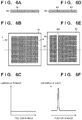
- the dispenser 11 has an arrangement in which a plurality of orifices 61 for discharging droplets of the resin R are laid out in a line, as shown in FIGS. 6A and 6D , in order to shorten the time taken to supply the resin R to the substrate W.
- the resin R is supplied to the substrate W by discharging droplets of the resin R from the plurality of orifices 61 of the dispenser 11 while moving the substrate stage 2 in a scan direction 62 , as shown in FIGS. 6B and 6E .
- FIG. 6B shows an image sensed by the image sensor 9 b when the supply of the resin R to the substrate W was normally performed, and shows the layout of droplets of the resin R on the substrate to which the dispenser 11 has supplied the resin R. Referring to FIG. 6B , it can be confirmed that droplets of the resin R have uniformly been formed on the substrate, and droplets of the resin R that should be supplied to the substrate are not omitted.
- FIG. 6E shows an image sensed by the image sensor 9 b when the supply of the resin R to the substrate W was not normally performed, for example, when dust is attached to an orifice 63 out of the plurality of orifices 61 of the dispenser 11 and droplets of the resin R cannot be discharged.
- FIG. 6E it can be confirmed that droplets of the resin R are omitted in a region 64 on the substrate corresponding to the orifice 63 of the dispenser 11 .
- step S 202 it is determined whether droplets of the resin R that should be supplied to the substrate are omitted.
- a reference for determining the normality/abnormality of imprint processing an image of droplets of the resin R normally discharged from the dispenser 11 is used.
- an image sensed by the image sensor 9 b in the supply process is compared with (the reference layout of droplets of the resin R in) a reference image obtained when the dispenser 11 normally discharged droplets of the resin R.
- FIG. 6C is a graph showing the luminance of the image shown in FIG. 6B along a broken line 65 .
- the ordinate represents the luminance in the image
- the abscissa represents the position in the image.
- the ordinate represents the luminance in the image
- the abscissa represents the position in the image.
- step S 202 the normality/abnormality of imprint processing is determined. If it is determined that imprint processing is abnormal, the imprint processing is stopped, and it can be prevented to produce defectives in which, for example, part of a pattern on a substrate is lost. If the omission of droplets of the resin R that should be supplied onto the substrate is detected as an abnormality of imprint processing in step S 202 , a removal process for dust attached to the dispenser 11 (orifices) is automatically performed, and the imprint processing can be continued.
- step S 203 the normality/abnormality of imprint processing is determined based on an image sensed by the observation unit 9 (image sensor 9 b ) after the start (step S 102 - 1 ) of the impress process. In the determination of the normality/abnormality of imprint processing in step S 203 , it is determined whether a particle is attached to the substrate W.
- step S 203 The determination of the normality/abnormality of imprint processing in step S 203 will be explained in detail.
- whether a particle is attached to the substrate W is determined using a difference image representing the difference in luminance for each pixel at the same position between a reference image and an image sensed by the image sensor 9 b after the start (step S 102 - 1 ) of the impress process.
- a reference for determining the normality/abnormality of imprint processing an image obtained when the impress process was normally performed is used.
- the reference image is an image sensed by the image sensor 9 b after the start (step S 102 - 1 ) of the impress process when imprint processing is normal.
- FIG. 7B shows a difference image obtained when no particle is attached to the substrate W, as shown in FIG. 7A .
- the difference image shown in FIG. 7B is a difference image that does not greatly change and includes only low luminance values. This is because normal images are compared with each other.
- FIG. 7D shows a difference image obtained when a particle G is attached to the substrate W, as shown in FIG. 7C .
- the difference image shown in FIG. 7D is a difference image that includes even a high luminance value because a large difference is generated between the image and the reference image at a portion G′ where the particle G attached to the substrate W exists.
- the difference image between the reference image and the image sensed by the image sensor 9 b after the start of the impress process includes a luminance value exceeding a predetermined luminance value, it can be determined that the particle G is attached to the substrate W, that is, imprint processing is abnormal.
- the determination (step S 203 ) of whether the particle G is attached to the substrate W is preferably performed at a timing when the mold M and the resin R on the substrate contact each other. It can therefore be early determined that the particle G is attached to the substrate W (abnormality of imprint processing).
- the impress process is stopped and the damage of the mold M can be avoided. Not only the particle G attached to the substrate, but also a particle attached to the mold M can be determined. In this manner, the presence/absence of a particle between the mold M and the substrate W can be determined (detected).
- FIG. 8 is a graph for explaining the timing to perform the determination (step S 203 ) of the normality/abnormality of imprint processing.
- the ordinate represents the output (force detected by the force sensor 16 ) of the force sensor 16 arranged on the substrate chuck 1
- the abscissa represents the time from the start of the impress process to the end of the impress process.
- FIG. 8 shows a change of the force (impress force) generated by the contact between the mold M and the resin R on the substrate in the impress process.
- the mold M and the resin R on the substrate are spaced apart from each other at the start time of the impress process, so the output of the force sensor 16 is 0.
- the output of the force sensor 16 gradually increases.
- the force sensor 16 detects a force generated by the contact between the mold M and the resin R on the substrate, it is determined whether the particle G is attached to the substrate W. In some cases, there is a time allowance until the mold M and the particle G attached to the substrate W contact each other after the mold M and the resin R on the substrate contact each other.
- the particle G is attached to the substrate W at a timing T 1 when the output of the force sensor 16 exceeds a threshold Th.
- the timing when the mold M and the resin R on the substrate contact each other can also be detected not using the force sensor 16 , but using an image sensed by the observation unit 9 (image sensor 9 b ).
- the presence/absence of a particle between the mold M and the substrate W is determined at the timing when the size (diameter) of interference fringes sensed by the image sensor 9 b becomes larger than a predetermined size PS.
- step S 204 parallel to step S 203 , the normality/abnormality of imprint processing is determined based on the image sensed by the observation unit 9 (image sensor 9 b ) after the start (step S 102 - 1 ) of the impress process.
- the image of interference fringes sensed by the image sensor 9 b is used.
- the contact state between the mold M and the resin R on the substrate, and the mutual postures of the mold M and resin R are determined based on interference fringes as shown in FIG. 2B .
- information about at least either of the position and roundness of sensed interference fringes as shown in FIG. 2B is obtained. Based on this information, it is determined whether the mold M in a tilt state contacts the resin R on the substrate.
- the information about at least either of the position and roundness of interference fringes can be obtained by comparing interference fringes sensed by the image sensor 9 b after the start of the impress process with reference interference fringes obtained when the mold M and the resin R on the substrate normally contacted each other.
- step S 204 determination of the normality/abnormality of imprint processing in step S 204 is the same as the determination (step S 205 ) of the normality/abnormality of imprint processing performed after the start (step S 104 - 1 ) of the release process (to be described later), and a detailed description thereof will not be repeated.
- FIG. 9 shows an alignment signal generated by the alignment scope 5 .
- the ordinate represents the strength of the alignment signal
- the abscissa represents the time from the start of the impress process to the end of the impress process.
- FIG. 10A shows the states of the mold M and substrate W at a timing T A shown in FIG. 9 .
- the alignment scope 5 detects the mold-side mark 7 and the substrate-side mark 6 by detecting reflected light RL.
- the mold-side mark 7 and the substrate-side mark 6 are spaced apart from each other, as shown in FIG. 10A , they cannot be detected, and the alignment signal shown in FIG. 9 is not generated.
- FIG. 10B shows the states of the mold M and substrate W at a timing T B shown in FIG. 9 .
- the mold M and the resin R on the substrate contact each other, and the resin R starts filling the pattern P of the mold M.
- the mold-side mark 7 and the substrate-side mark 6 come close to each other, the mold-side mark 7 and the substrate-side mark 6 are being detected.
- the reflected light RL fluctuates depending on the motion of the resin R.
- the alignment signal generated by the alignment scope 5 varies, as shown in FIG. 9 .
- FIG. 10C shows the states of the mold M and substrate W at a timing T C shown in FIG. 9 .
- the pattern P of the mold M is sufficiently filled with the resin R on the substrate, so the resin R does not move and the reflected light RL is stabilized.
- the alignment signal generated by the alignment scope 5 is also stabilized, as shown in FIG. 9 .
- the timing to perform the determination (step S 204 ) of the normality/abnormality of imprint processing can be specified.
- the present invention is not limited to this, and the timing to perform the determination (step S 204 ) of the normality/abnormality of imprint processing may be specified using the force sensor 16 , as described above, instead of the alignment scope 5 .
- whether the mold M in a tilt state contacts the resin R on the substrate is determined at the timing when the output of the force sensor 16 exceeds the threshold or the timing when the force sensor 16 detects a force generated by the contact between the mold M and the resin R on the substrate.
- step S 205 parallel to steps S 203 and S 204 , the normality/abnormality of imprint processing is determined based on the image sensed by the observation unit 9 (image sensor 9 b ) after the start (step S 102 - 1 ) of the impress process. In the determination of the normality/abnormality of imprint processing in step S 205 , it is determined whether droplets of the resin R that should be supplied from the dispenser 11 onto the substrate are omitted.
- the dispenser 11 has an arrangement in which the plurality of orifices 61 for discharging droplets of the resin R are laid out in a line, as shown in FIGS. 14A and 14C , in order to shorten the time taken to supply the resin R to the substrate W.
- the resin R is supplied to the substrate W by discharging droplets of the resin R from the plurality of orifices 61 of the dispenser 11 while moving the substrate stage 2 in the scan direction 62 , as shown in FIGS. 14B and 14D .
- FIG. 14B shows an image sensed by the image sensor 9 b during the impress process when the supply of the resin R to the substrate W was normally performed, and shows a state in which the pattern P of the mold M is filled with the resin R by the impress process.
- FIG. 14B shows interference fringes at the timing after the impress process proceeds, and a circle at the center of the interference fringes spreads to the entire surface of the mold M (pattern P) in the interference fringes ( FIGS. 2A and 2B ) observed in the impress process. Referring to FIG. 11B , it can be confirmed that the luminance of pixels does not vary in a region corresponding to the mold M (pattern P), and droplets of the resin R that should be supplied onto the substrate are not omitted.
- FIG. 14D shows an image sensed by the image sensor 9 b during the impress process when the supply of the resin R to the substrate W was not normally performed.
- the case in which the supply of the resin R to the substrate W was not normally performed is, for example, a case in which dust is attached to the orifice 63 out of the plurality of orifices 61 of the dispenser 11 , and droplets of the resin R cannot be discharged from the orifice 63 .
- FIG. 14D it can be confirmed that the luminance of pixels in the region 64 on the substrate corresponding to the orifice 63 of the dispenser 11 is different from that in the remaining region.
- FIGS. 15A and 15B are views for explaining interference fringes observed in FIG. 14D .
- FIG. 15A shows a gap between the mold M and the substrate W while the impress process is performed, and the state of filling the pattern P of the mold M with the resin R.
- FIG. 15B shows part of an image sensed by the image sensor 9 b .
- the mold M and resin R close in refractive index contact each other in a region 121 where droplets of the resin R are not omitted, so the reflectance at the interface between the mold M and the resin R becomes very low.
- reflected light in the region 121 where droplets of the resin R are not omitted becomes weak, and a dark image is obtained in the image sensor 9 b.
- interference fringes include a case in which there is one bright streak owing to the omission of droplets at one portion, as shown in FIG. 11D , and a case in which a plurality of variable-density streaks are repeated owing to the omission of droplets at a plurality of portions.
- step S 205 it is determined whether droplets of the resin R that should be supplied from the dispenser 11 onto the substrate are omitted. At this time, an image sensed by the image sensor 9 b in the impress process is compared with a reference image obtained when the dispenser 11 normally discharged droplets of the resin R.
- the determination of the normality/abnormality of imprint processing in step S 205 will be explained in detail by exemplifying a case in which the presence/absence of a vertical streak (bright/dark line) in the scan direction (moving direction) in an image sensed by the image sensor 9 b is used.
- FIG. 16 shows a difference image between the image shown in FIG. 14B and the image shown in FIG. 14D .
- a pixel having a difference becomes white, and a pixel having no difference becomes dark in the difference image.
- a boundary 131 at which the brightness of a pixel changes is extracted from the difference image. The presence/absence of a vertical streak in the scan direction is determined based on whether the boundary 131 is parallel to the scan direction 62 , that is, whether the boundary 131 is approximate to a straight line indicating the scan direction 62 .
- step S 202 the determination of whether droplets of the resin R are omitted is performed even in step S 202 .
- step S 202 droplets of the resin R on the substrate are directly observed, so the luminance of each pixel changes depending on the presence/absence of a droplet in an image obtained by the image sensor 9 b , as shown in FIG. 6B .
- step S 205 the impress process is started, interference fringes when the pattern P of the mold M is filled with the resin R are observed, and the luminance of each pixel hardly changes, as shown in FIGS. 14B and 14D .
- step S 205 compared to step S 202 , a low resolution of the image sensor 9 b is permitted, and the omission of droplets of the resin R can be detected as a clearer vertical streak.
- the timing to perform the determination (step S 205 ) of the normality/abnormality of imprint processing may be the timing when the pattern P of the mold M is filled with the resin R, like the timing T D shown in FIG. 9 .
- the region 64 (vertical streak) detected when droplets of the resin R are omitted can be detected even during filling with the resin R during which the interference fringes shown in FIGS. 2A and 2B are obtained. Therefore, the timing to perform the determination (step S 205 ) of the normality/abnormality of imprint processing is not limited to the timing T D shown in FIG. 9 , and can be an arbitrary timing when the region 64 shown in FIG. 14D can be detected.
- step S 205 the normality/abnormality of imprint processing is determined. If it is determined that imprint processing is abnormal, the imprint processing is stopped, and it can be prevented to produce defectives in which, for example, part of a pattern on a substrate is lost. If the omission of droplets of the resin R that should be supplied onto the substrate is detected as an abnormality of imprint processing in step S 205 , a removal process for dust attached to the dispenser 11 (orifices) is automatically performed, and the imprint processing can be continued.
- step S 206 the normality/abnormality of imprint processing is determined based on an image sensed by the observation unit 9 (image sensor 9 b ) after the start (step S 104 - 1 ) of the release process.
- the release process if the mold M in a tilt state is released from the cured resin R on the substrate, as shown in FIG. 11A , the pattern of the resin R formed on the substrate may fall down or be damaged.
- step S 206 whether the mold M in a tilt state is being released from the cured resin R on the substrate is determined based on interference fringes as shown in FIG. 2B or 11B .
- the image of interference fringes sensed by the image sensor 9 b is used. More specifically, positions Pos X and Pos Y, and a roundness (ratio of Width and Height) of interference fringes are obtained first, as shown in FIG. 11B .
- the positions and roundness of interference fringes can be obtained by comparing interference fringes sensed by the image sensor 9 b after the start of the release process with reference interference fringes obtained when the mold M was normally released from the resin R on the substrate. When the positions and roundness of the interference fringes exceed thresholds, it is determined that the mold M in a tilt state is being released from the cured resin R on the substrate, that is, imprint processing is abnormal. In this manner, even when the state of the substrate W greatly changes in a short period, the normality/abnormality of imprint processing can be determined at high accuracy by using interference fringes sensed by the image sensor 9 b.
- FIGS. 12A to 12C show images (interference fringes) sensed by the image sensor 9 b with the lapse of time of the release process.
- the mold M is deformed into a shape projecting toward the substrate in order to reduce a release force, which is a force for releasing the mold M from the cured resin R on the substrate, as described above.
- the mold M is released from the cured resin R on the substrate from the periphery of the mold M, and the peeling of the resin R from the substrate W can be prevented.
- this embodiment can specify the timing to determine whether the mold M in a tilt state is being released from the cured resin R on the substrate.
- step S 207 the normality/abnormality of imprint processing is determined based on an image sensed by the observation unit 9 (image sensor 9 b ) after the release process.
- the image of interference fringes sensed by the image sensor 9 b is used.
- FIG. 13A shows an image sensed by the image sensor 9 b when the release step has been performed normally. If the pattern P of the mold M is a periodic line-and-space pattern, an image is obtained, in which the luminance is low at the portion of the resin R formed on the substrate W and high at the remaining portion, as shown in FIG. 13A .
- FIG. 13C shows an image sensed by the image sensor 9 b when the release step has not been performed normally, for example, when the resin R has peeled off the substrate W and is attached to the mold M. In this case, an image is obtained, in which the luminance is high at a portion 71 where the peeling of the resin R has occurred, as shown in FIG. 13C .
- whether the resin R has peeled off the substrate W is determined using a difference image representing the difference in luminance for each pixel at the same position between a reference image and an image sensed by the image sensor 9 b after the release process.
- the reference image is an image sensed by the image sensor 9 b after the release process when imprint processing is normal.
- FIG. 13B shows a difference image obtained when the resin R has not peeled off the substrate W, as shown in FIG. 13A .
- the difference image shown in FIG. 13B is a difference image that does not greatly change and includes only low luminance values. This is because normal images are compared with each other.
- FIG. 13D shows a difference image obtained when the resin R has peeled off the substrate W, as shown in FIG. 13A .
- the difference image shown in FIG. 13D is a difference image that includes even a high luminance value because a large difference is generated between the image and the reference image at a portion 72 where the peeling of the resin R has occurred.
- the difference image between the reference image and the image sensed by the image sensor 9 b after the start of the release process includes a luminance value exceeding a predetermined luminance value, it can be determined that the resin R has peeled off the substrate W, that is, imprint processing is abnormal.
- the determination of the normality/abnormality of imprint processing using such a difference image is effective even when determining the normality/abnormality of imprint processing on a substrate having an underlayer on which a pattern has already been formed. In this case, a reference image needs to be prepared for each underlayer.
- the imprint apparatus 100 can accurately determine the normality/abnormality of imprint processing by grasping the state of the substrate W at high accuracy in each process of imprint processing.
- the imprint apparatus 100 can suppress the influence of an abnormality of imprint processing and increase the productivity.
- the imprint apparatus 100 uses pieces of information from the alignment scope 5 , the force sensor 16 , and the observation unit 9 to specify the timing to determine the normality/abnormality of imprint processing. Not the timing when each process of imprint processing is switched, but the timing suitable for determining the normality/abnormality of imprint processing can be specified. In the impress process and the like, the normality/abnormality of imprint processing can be determined at different timings corresponding to states of the substrate W.
- the normality/abnormality of imprint processing is determined in the supply process, impress process, and release process according to this embodiment, the present invention is not limited to this.
- the normality/abnormality of imprint processing may be determined in at least two of the supply process, impress process, and release process, or at least either of the supply step and impress step.
- the normality/abnormality of imprint processing may be determined even at an interval between the impress step and the cure step or an interval between the cure step and the release step.
- an error process corresponding to the abnormality is performed. For example, when it is determined in step S 203 that the particle G is attached to the substrate W, a process of removing the particle G can be performed, or a process of storing a position on the substrate at which the particle G is attached can be performed. When the particle G cannot be removed, imprint processing may be stopped, or the mold M may be inhibited from contacting the particle G (from forming a pattern).
- the resin curing method is not limited to the photo-curing method, and may be a heat cycle method.
- a thermoplastic resin is heated to a temperature equal to or higher than a glass transition temperature to enhance fluidity.
- the mold and the resin are brought into contact with each other, and the resin is cooled and cured.
- the mold is released from the cured resin on the substrate, thereby forming a pattern on the substrate.
- This manufacturing method includes a step of forming a pattern on a substrate (for example, a wafer, glass plate, or film substrate) using the imprint apparatus 100 .
- This manufacturing method further includes a step of processing the substrate on which the pattern has been formed.
- the processing step can include a step of removing the residual film of the pattern.
- the method can include other known steps such as a step of etching the substrate using the pattern as a mask.
- the method of manufacturing an article according to this embodiment is advantageous over the related art in terms of at least one of the performance, quality, productivity, and production cost of articles.
Abstract
Description
Claims (23)
Applications Claiming Priority (4)
| Application Number | Priority Date | Filing Date | Title |
|---|---|---|---|
| JP2014-249197 | 2014-12-09 | ||
| JP2014249197 | 2014-12-09 | ||
| JP2015-194405 | 2015-09-30 | ||
| JP2015194405A JP6674218B2 (en) | 2014-12-09 | 2015-09-30 | Imprint apparatus, imprint method, and article manufacturing method |
Publications (2)
| Publication Number | Publication Date |
|---|---|
| US20160158978A1 US20160158978A1 (en) | 2016-06-09 |
| US10747106B2 true US10747106B2 (en) | 2020-08-18 |
Family
ID=56093463
Family Applications (1)
| Application Number | Title | Priority Date | Filing Date |
|---|---|---|---|
| US14/962,006 Active 2038-07-09 US10747106B2 (en) | 2014-12-09 | 2015-12-08 | Imprint apparatus |
Country Status (1)
| Country | Link |
|---|---|
| US (1) | US10747106B2 (en) |
Families Citing this family (5)
| Publication number | Priority date | Publication date | Assignee | Title |
|---|---|---|---|---|
| JP6541518B2 (en) * | 2015-09-04 | 2019-07-10 | キヤノン株式会社 | Imprint apparatus, imprint method, and article manufacturing method |
| JP6716160B2 (en) * | 2016-05-31 | 2020-07-01 | 株式会社ディスコ | Processing device and processing method |
| US11681216B2 (en) * | 2017-08-25 | 2023-06-20 | Canon Kabushiki Kaisha | Imprint apparatus, imprint method, article manufacturing method, molding apparatus, and molding method |
| JP7086711B2 (en) * | 2018-05-18 | 2022-06-20 | キヤノン株式会社 | Imprint device and article manufacturing method |
| TW202319213A (en) * | 2021-07-30 | 2023-05-16 | 日商佳能股份有限公司 | Information processing apparatus, molding apparatus, molding method, and article manufacturing method |
Citations (17)
| Publication number | Priority date | Publication date | Assignee | Title |
|---|---|---|---|---|
| JP2005353858A (en) | 2004-06-11 | 2005-12-22 | Canon Inc | Processing unit and method therefor |
| US20060032437A1 (en) * | 2004-08-13 | 2006-02-16 | Molecular Imprints, Inc. | Moat system for an imprint lithography template |
| US20060126058A1 (en) * | 2004-11-30 | 2006-06-15 | Molecular Imprints, Inc. | Interferometric analysis for the manufacture of nano-scale devices |
| US20070018360A1 (en) | 2005-07-21 | 2007-01-25 | Asml Netherlands B.V. | Imprint lithography |
| US20090140445A1 (en) * | 2007-12-04 | 2009-06-04 | Molecular Imprints | High Throughput Imprint Based on Contact Line Motion Tracking Control |
| JP2009286067A (en) | 2008-05-30 | 2009-12-10 | Toshiba Mach Co Ltd | Transfer device, press apparatus, and position attitude adjustment mechanism |
| US20100101493A1 (en) | 2008-10-27 | 2010-04-29 | Molecular Imprints, Inc. | Dispense System |
| JP2010149469A (en) | 2008-12-26 | 2010-07-08 | Showa Denko Kk | Imprinting device and method of detecting contamination of mold |
| US20100314798A1 (en) | 2009-06-16 | 2010-12-16 | Canon Kabushiki Kaisha | Imprint apparatus and method of manufacturing article |
| JP2011091235A (en) | 2009-10-23 | 2011-05-06 | Canon Inc | Imprinting method and device, and method of manufacturing article using the same |
| JP2011114309A (en) | 2009-11-30 | 2011-06-09 | Canon Inc | Imprint apparatus |
| US20110206852A1 (en) * | 2010-02-24 | 2011-08-25 | Canon Kabushiki Kaisha | Imprint apparatus, template of imprint apparatus, and article manufacturing method |
| US20120072003A1 (en) | 2010-09-22 | 2012-03-22 | Yasuo Matsuoka | Imprinting method, semiconductor integrated circuit manufacturing method and drop recipe creating method |
| JP2012125942A (en) | 2010-12-13 | 2012-07-05 | Toshiba Mach Co Ltd | Master mold manufacturing apparatus |
| JP2013058517A (en) | 2011-09-07 | 2013-03-28 | Canon Inc | Imprint device, and method for manufacturing article using the same |
| JP2014064022A (en) | 2013-11-11 | 2014-04-10 | Canon Inc | Imprint device |
| US20150076724A1 (en) * | 2013-09-13 | 2015-03-19 | Canon Kabushiki Kaisha | Imprint apparatus, imprint method, detecting method, and method of manufacturing device |
-
2015
- 2015-12-08 US US14/962,006 patent/US10747106B2/en active Active
Patent Citations (22)
| Publication number | Priority date | Publication date | Assignee | Title |
|---|---|---|---|---|
| JP2005353858A (en) | 2004-06-11 | 2005-12-22 | Canon Inc | Processing unit and method therefor |
| US20060032437A1 (en) * | 2004-08-13 | 2006-02-16 | Molecular Imprints, Inc. | Moat system for an imprint lithography template |
| US20060126058A1 (en) * | 2004-11-30 | 2006-06-15 | Molecular Imprints, Inc. | Interferometric analysis for the manufacture of nano-scale devices |
| US20070018360A1 (en) | 2005-07-21 | 2007-01-25 | Asml Netherlands B.V. | Imprint lithography |
| US20090140445A1 (en) * | 2007-12-04 | 2009-06-04 | Molecular Imprints | High Throughput Imprint Based on Contact Line Motion Tracking Control |
| CN101884019A (en) | 2007-12-04 | 2010-11-10 | 分子制模股份有限公司 | High throughput imprint based on contact line motion tracking control |
| JP2009286067A (en) | 2008-05-30 | 2009-12-10 | Toshiba Mach Co Ltd | Transfer device, press apparatus, and position attitude adjustment mechanism |
| US20100101493A1 (en) | 2008-10-27 | 2010-04-29 | Molecular Imprints, Inc. | Dispense System |
| JP2010149469A (en) | 2008-12-26 | 2010-07-08 | Showa Denko Kk | Imprinting device and method of detecting contamination of mold |
| JP2011003616A (en) | 2009-06-16 | 2011-01-06 | Canon Inc | Imprint apparatus and method of manufacturing article |
| US20100314798A1 (en) | 2009-06-16 | 2010-12-16 | Canon Kabushiki Kaisha | Imprint apparatus and method of manufacturing article |
| US8734701B2 (en) | 2009-06-16 | 2014-05-27 | Canon Kabushiki Kaisha | Imprint apparatus and method of manufacturing article |
| JP2011091235A (en) | 2009-10-23 | 2011-05-06 | Canon Inc | Imprinting method and device, and method of manufacturing article using the same |
| JP2011114309A (en) | 2009-11-30 | 2011-06-09 | Canon Inc | Imprint apparatus |
| US20110206852A1 (en) * | 2010-02-24 | 2011-08-25 | Canon Kabushiki Kaisha | Imprint apparatus, template of imprint apparatus, and article manufacturing method |
| JP2011176132A (en) | 2010-02-24 | 2011-09-08 | Canon Inc | Imprint device, template thereof, and method for manufacturing article |
| US20120072003A1 (en) | 2010-09-22 | 2012-03-22 | Yasuo Matsuoka | Imprinting method, semiconductor integrated circuit manufacturing method and drop recipe creating method |
| JP2012069701A (en) | 2010-09-22 | 2012-04-05 | Toshiba Corp | Imprint method, semiconductor integrated circuit manufacturing method, and drop recipe preparation method |
| JP2012125942A (en) | 2010-12-13 | 2012-07-05 | Toshiba Mach Co Ltd | Master mold manufacturing apparatus |
| JP2013058517A (en) | 2011-09-07 | 2013-03-28 | Canon Inc | Imprint device, and method for manufacturing article using the same |
| US20150076724A1 (en) * | 2013-09-13 | 2015-03-19 | Canon Kabushiki Kaisha | Imprint apparatus, imprint method, detecting method, and method of manufacturing device |
| JP2014064022A (en) | 2013-11-11 | 2014-04-10 | Canon Inc | Imprint device |
Non-Patent Citations (4)
| Title |
|---|
| Office Action issued in Chinese Appln. No. 201510885990.6 dated Apr. 3, 2019. |
| Office Action issued in Japanese Appln. No. 2015-194405 dated Jun. 18, 2019. |
| Office Action issued in Korean Appln. No. 10-2015-0169819 dated Jan. 17, 2019. |
| Office Action issued in Taiwanese Appln. No. 104135429 dated Aug. 15, 2016. English translation provided. |
Also Published As
| Publication number | Publication date |
|---|---|
| US20160158978A1 (en) | 2016-06-09 |
Similar Documents
| Publication | Publication Date | Title |
|---|---|---|
| JP6931408B2 (en) | A device for curing an uncured material, a method for determining whether or not an uncured material is discharged, and a method for manufacturing an article for curing an uncured material. | |
| US10747106B2 (en) | Imprint apparatus | |
| US10751930B2 (en) | Imprint apparatus, imprint method, and method of manufacturing article | |
| US20230166430A1 (en) | Imprint apparatus, method of manufacturing article, planarized layer forming apparatus, information processing apparatus, and determination method | |
| US9810979B2 (en) | Imprint apparatus and article manufacturing method | |
| US20130134616A1 (en) | Imprint apparatus, imprint method, and article manufacturing method | |
| US20180074419A1 (en) | Methods of forming patterns using nanoimprint lithography | |
| US10611063B2 (en) | Imprint apparatus, and method of manufacturing article | |
| KR102293478B1 (en) | Imprint apparatus and method of manufacturing article | |
| JP5936373B2 (en) | Imprint apparatus, imprint apparatus control method, and device manufacturing method | |
| KR102026503B1 (en) | Imprint apparatus, imprint method, and method of manufacturing article | |
| US20160207248A1 (en) | Imprint apparatus, imprinting method, and method of manufacturing articles | |
| JP2018010942A (en) | Imprint device and manufacturing method of article | |
| US11681216B2 (en) | Imprint apparatus, imprint method, article manufacturing method, molding apparatus, and molding method | |
| KR20190022385A (en) | Imprint apparatus, imprint method, article manufacturing method, molding apparatus, and molding method | |
| JP2018156986A (en) | Imprint apparatus, defect inspection method, pattern formation method, and article manufacturing method | |
| US20180370091A1 (en) | Imprint apparatus, method of manufacturing article, information processing apparatus, method of supporting map editing, and storage medium | |
| JP7361831B2 (en) | Information processing equipment, molding equipment, molding methods, and article manufacturing methods | |
| JP2019087732A (en) | Imprint apparatus, information processing apparatus, and article manufacturing method | |
| US20230036274A1 (en) | Information processing apparatus, molding apparatus, molding method, and article manufacturing method | |
| US11698585B2 (en) | Imprint method, imprint apparatus, determination method, and article manufacturing method | |
| JP2018006379A (en) | Imprint device and manufacturing method of article | |
| JP7043199B2 (en) | Imprint method, program, imprint device and manufacturing method of goods |
Legal Events
| Date | Code | Title | Description |
|---|---|---|---|
| AS | Assignment |
Owner name: CANON KABUSHIKI KAISHA, JAPAN Free format text: ASSIGNMENT OF ASSIGNORS INTEREST;ASSIGNORS:AIHARA, SENTARO;UENO, TAKEHIKO;REEL/FRAME:037900/0951 Effective date: 20151112 |
|
| STPP | Information on status: patent application and granting procedure in general |
Free format text: NON FINAL ACTION MAILED |
|
| STPP | Information on status: patent application and granting procedure in general |
Free format text: RESPONSE TO NON-FINAL OFFICE ACTION ENTERED AND FORWARDED TO EXAMINER |
|
| STPP | Information on status: patent application and granting procedure in general |
Free format text: FINAL REJECTION MAILED |
|
| STPP | Information on status: patent application and granting procedure in general |
Free format text: ADVISORY ACTION MAILED |
|
| STPP | Information on status: patent application and granting procedure in general |
Free format text: DOCKETED NEW CASE - READY FOR EXAMINATION |
|
| STPP | Information on status: patent application and granting procedure in general |
Free format text: NON FINAL ACTION MAILED |
|
| STPP | Information on status: patent application and granting procedure in general |
Free format text: RESPONSE TO NON-FINAL OFFICE ACTION ENTERED AND FORWARDED TO EXAMINER |
|
| STPP | Information on status: patent application and granting procedure in general |
Free format text: NOTICE OF ALLOWANCE MAILED -- APPLICATION RECEIVED IN OFFICE OF PUBLICATIONS |
|
| STPP | Information on status: patent application and granting procedure in general |
Free format text: PUBLICATIONS -- ISSUE FEE PAYMENT VERIFIED |
|
| STCF | Information on status: patent grant |
Free format text: PATENTED CASE |
|
| MAFP | Maintenance fee payment |
Free format text: PAYMENT OF MAINTENANCE FEE, 4TH YEAR, LARGE ENTITY (ORIGINAL EVENT CODE: M1551); ENTITY STATUS OF PATENT OWNER: LARGE ENTITY Year of fee payment: 4 |