US10744903B2 - Method for controlling fuel cell vehicles and fuel cell vehicles - Google Patents

Method for controlling fuel cell vehicles and fuel cell vehicles Download PDF

Info

Publication number
US10744903B2
US10744903B2 US14/938,117 US201514938117A US10744903B2 US 10744903 B2 US10744903 B2 US 10744903B2 US 201514938117 A US201514938117 A US 201514938117A US 10744903 B2 US10744903 B2 US 10744903B2
Authority
US
United States
Prior art keywords
fuel cell
warning
control unit
electronic control
controlling
Prior art date
Legal status (The legal status is an assumption and is not a legal conclusion. Google has not performed a legal analysis and makes no representation as to the accuracy of the status listed.)
Active
Application number
US14/938,117
Other versions
US20160129807A1 (en
Inventor
Yohei Okamoto
Hiroyuki Imanishi
Mitsuhiro Nada
Takashi Yamada
Current Assignee (The listed assignees may be inaccurate. Google has not performed a legal analysis and makes no representation or warranty as to the accuracy of the list.)
Toyota Motor Corp
Original Assignee
Toyota Motor Corp
Priority date (The priority date is an assumption and is not a legal conclusion. Google has not performed a legal analysis and makes no representation as to the accuracy of the date listed.)
Filing date
Publication date
Application filed by Toyota Motor Corp filed Critical Toyota Motor Corp
Assigned to TOYOTA JIDOSHA KABUSHIKI KAISHA reassignment TOYOTA JIDOSHA KABUSHIKI KAISHA ASSIGNMENT OF ASSIGNORS INTEREST (SEE DOCUMENT FOR DETAILS). Assignors: NADA, MITSUHIRO, YAMADA, TAKASHI, IMANISHI, HIROYUKI, OKAMOTO, Yohei
Publication of US20160129807A1 publication Critical patent/US20160129807A1/en
Priority to US16/899,267 priority Critical patent/US11491893B2/en
Application granted granted Critical
Publication of US10744903B2 publication Critical patent/US10744903B2/en
Active legal-status Critical Current
Anticipated expiration legal-status Critical

Links

Images

Classifications

    • BPERFORMING OPERATIONS; TRANSPORTING
    • B60VEHICLES IN GENERAL
    • B60LPROPULSION OF ELECTRICALLY-PROPELLED VEHICLES; SUPPLYING ELECTRIC POWER FOR AUXILIARY EQUIPMENT OF ELECTRICALLY-PROPELLED VEHICLES; ELECTRODYNAMIC BRAKE SYSTEMS FOR VEHICLES IN GENERAL; MAGNETIC SUSPENSION OR LEVITATION FOR VEHICLES; MONITORING OPERATING VARIABLES OF ELECTRICALLY-PROPELLED VEHICLES; ELECTRIC SAFETY DEVICES FOR ELECTRICALLY-PROPELLED VEHICLES
    • B60L3/00Electric devices on electrically-propelled vehicles for safety purposes; Monitoring operating variables, e.g. speed, deceleration or energy consumption
    • B60L3/04Cutting off the power supply under fault conditions
    • BPERFORMING OPERATIONS; TRANSPORTING
    • B60VEHICLES IN GENERAL
    • B60LPROPULSION OF ELECTRICALLY-PROPELLED VEHICLES; SUPPLYING ELECTRIC POWER FOR AUXILIARY EQUIPMENT OF ELECTRICALLY-PROPELLED VEHICLES; ELECTRODYNAMIC BRAKE SYSTEMS FOR VEHICLES IN GENERAL; MAGNETIC SUSPENSION OR LEVITATION FOR VEHICLES; MONITORING OPERATING VARIABLES OF ELECTRICALLY-PROPELLED VEHICLES; ELECTRIC SAFETY DEVICES FOR ELECTRICALLY-PROPELLED VEHICLES
    • B60L58/00Methods or circuit arrangements for monitoring or controlling batteries or fuel cells, specially adapted for electric vehicles
    • B60L58/30Methods or circuit arrangements for monitoring or controlling batteries or fuel cells, specially adapted for electric vehicles for monitoring or controlling fuel cells
    • BPERFORMING OPERATIONS; TRANSPORTING
    • B60VEHICLES IN GENERAL
    • B60QARRANGEMENT OF SIGNALLING OR LIGHTING DEVICES, THE MOUNTING OR SUPPORTING THEREOF OR CIRCUITS THEREFOR, FOR VEHICLES IN GENERAL
    • B60Q1/00Arrangement of optical signalling or lighting devices, the mounting or supporting thereof or circuits therefor
    • B60Q1/26Arrangement of optical signalling or lighting devices, the mounting or supporting thereof or circuits therefor the devices being primarily intended to indicate the vehicle, or parts thereof, or to give signals, to other traffic
    • B60Q1/50Arrangement of optical signalling or lighting devices, the mounting or supporting thereof or circuits therefor the devices being primarily intended to indicate the vehicle, or parts thereof, or to give signals, to other traffic for indicating other intentions or conditions, e.g. request for waiting or overtaking
    • B60Q1/543Arrangement of optical signalling or lighting devices, the mounting or supporting thereof or circuits therefor the devices being primarily intended to indicate the vehicle, or parts thereof, or to give signals, to other traffic for indicating other intentions or conditions, e.g. request for waiting or overtaking for indicating other states or conditions of the vehicle
    • HELECTRICITY
    • H01ELECTRIC ELEMENTS
    • H01MPROCESSES OR MEANS, e.g. BATTERIES, FOR THE DIRECT CONVERSION OF CHEMICAL ENERGY INTO ELECTRICAL ENERGY
    • H01M2250/00Fuel cells for particular applications; Specific features of fuel cell system
    • H01M2250/20Fuel cells in motive systems, e.g. vehicle, ship, plane
    • HELECTRICITY
    • H01ELECTRIC ELEMENTS
    • H01MPROCESSES OR MEANS, e.g. BATTERIES, FOR THE DIRECT CONVERSION OF CHEMICAL ENERGY INTO ELECTRICAL ENERGY
    • H01M8/00Fuel cells; Manufacture thereof
    • H01M8/04Auxiliary arrangements, e.g. for control of pressure or for circulation of fluids
    • H01M8/04298Processes for controlling fuel cells or fuel cell systems
    • H01M8/04313Processes for controlling fuel cells or fuel cell systems characterised by the detection or assessment of variables; characterised by the detection or assessment of failure or abnormal function
    • H01M8/04664Failure or abnormal function
    • HELECTRICITY
    • H01ELECTRIC ELEMENTS
    • H01MPROCESSES OR MEANS, e.g. BATTERIES, FOR THE DIRECT CONVERSION OF CHEMICAL ENERGY INTO ELECTRICAL ENERGY
    • H01M8/00Fuel cells; Manufacture thereof
    • H01M8/04Auxiliary arrangements, e.g. for control of pressure or for circulation of fluids
    • H01M8/04298Processes for controlling fuel cells or fuel cell systems
    • H01M8/04992Processes for controlling fuel cells or fuel cell systems characterised by the implementation of mathematical or computational algorithms, e.g. feedback control loops, fuzzy logic, neural networks or artificial intelligence
    • YGENERAL TAGGING OF NEW TECHNOLOGICAL DEVELOPMENTS; GENERAL TAGGING OF CROSS-SECTIONAL TECHNOLOGIES SPANNING OVER SEVERAL SECTIONS OF THE IPC; TECHNICAL SUBJECTS COVERED BY FORMER USPC CROSS-REFERENCE ART COLLECTIONS [XRACs] AND DIGESTS
    • Y02TECHNOLOGIES OR APPLICATIONS FOR MITIGATION OR ADAPTATION AGAINST CLIMATE CHANGE
    • Y02EREDUCTION OF GREENHOUSE GAS [GHG] EMISSIONS, RELATED TO ENERGY GENERATION, TRANSMISSION OR DISTRIBUTION
    • Y02E60/00Enabling technologies; Technologies with a potential or indirect contribution to GHG emissions mitigation
    • Y02E60/30Hydrogen technology
    • Y02E60/50Fuel cells
    • Y02T90/32
    • Y02T90/34
    • YGENERAL TAGGING OF NEW TECHNOLOGICAL DEVELOPMENTS; GENERAL TAGGING OF CROSS-SECTIONAL TECHNOLOGIES SPANNING OVER SEVERAL SECTIONS OF THE IPC; TECHNICAL SUBJECTS COVERED BY FORMER USPC CROSS-REFERENCE ART COLLECTIONS [XRACs] AND DIGESTS
    • Y02TECHNOLOGIES OR APPLICATIONS FOR MITIGATION OR ADAPTATION AGAINST CLIMATE CHANGE
    • Y02TCLIMATE CHANGE MITIGATION TECHNOLOGIES RELATED TO TRANSPORTATION
    • Y02T90/00Enabling technologies or technologies with a potential or indirect contribution to GHG emissions mitigation
    • Y02T90/40Application of hydrogen technology to transportation, e.g. using fuel cells

Definitions

  • the present invention relates to a method for controlling fuel cell vehicles including an external power-feeding device and enabling power-feeding externally.
  • a fuel cell is a clean energy source to let hydrogen as fuel gas and air (oxygen) undergo electrochemical reaction for power generation and discharge water only.
  • a fuel cell vehicle is configured to drive its motor by electricity generated by such a fuel cell for travelling.
  • fuel cell vehicles have attracted attention as a power-generating unit as well that enables power-feeding externally.
  • Some fuel cell vehicles therefore include an external power-feeding device to feed electricity generated by a fuel cell to the outside.
  • Known external power-feeding devices include an inverter circuit.
  • Patent Document 1 discloses issuance of warning to a driver on a driver seat if abnormality occurs at the inverter during external power feeding, for example.
  • Patent Document 1 if abnormality occurs at the inverter during external power feeding, warning is issued to a driver on a driver seat.
  • the warning method disclosed by Patent document 1 may fail to inform a user outside of the vehicle of a failure or deterioration of the fuel cell, and so power-feeding may stop before the user knows.
  • the present invention aims to provide a method for controlling a fuel cell vehicle capable of informing a user outside of the vehicle of the possibility that the fuel cell stops power generation and external power-feeding stops.
  • a method for controlling a fuel cell vehicle of the present invention is to control a fuel cell vehicle including an external power-feeding device, includes: when it is determined that a state of a fuel cell exceeds a limiting point where deterioration of the fuel cell or a failure of a driving device to supply fuel to the fuel cell occurs during external power feeding, issuing warning to outside of the vehicle before the fuel cell stops power generation.
  • the warning is preferably issued by an auxiliary device that is controlled by a controller of the fuel cell.
  • the warning may be issued by a horn or a lamp of the fuel cell vehicle.
  • the warning may be issued through rotation of a fan of a radiator of the fuel cell vehicle.
  • the fuel cell vehicle may be controlled to stop issuance of the warning.
  • the method for controlling a fuel cell vehicle of the present invention since warning is issued to the outside of the vehicle before the fuel cell stops power generation, a user who is outside of the vehicle can be informed of the possibility that the fuel cell stops power generation and external power-feeding stops. The user therefore can perform adequate processing before external power-feeding stops, whereby problems due to unexpected stopping of power feeding can be avoided.
  • FIG. 1 schematically illustrates a fuel cell vehicle, to which a method for controlling fuel cell vehicles according to the first embodiment of the present invention is applied.
  • FIG. 2 is a flowchart of the method for controlling a fuel cell vehicle according to the first embodiment.
  • FIG. 3 is to explain the method for controlling a fuel cell vehicle according to the first embodiment.
  • FIG. 4 schematically illustrates a fuel cell vehicle, to which a method for controlling fuel cell vehicles according to the second embodiment of the present invention is applied.
  • FIG. 5 is to explain the method for controlling a fuel cell vehicle according to the second embodiment.
  • FIG. 1 schematically illustrates a fuel cell vehicle, to which a method for controlling fuel cell vehicles according to the first embodiment of the present invention is applied.
  • a fuel cell vehicle 100 is configured to drive a motor 30 by electricity generated by a fuel cell 20 for travelling.
  • the fuel cell 20 receives hydrogen as fuel gas supplied from a hydrogen tank 40 by a pump 22 , and receives air by a compressor 24 .
  • the fuel cell vehicle includes a battery not illustrated, and so is configured to be capable of storing surplus electricity of the fuel cell 20 and regenerative electricity of the fuel cell vehicle 100 in the battery.
  • the fuel cell 20 has a stack, in which a plurality of cells are stacked (none of them are illustrated).
  • a cell of a polymer electrolyte fuel cell at least includes a membrane electrode assembly (MEA) made up of an electrolyte membrane having ion permeability, and an anode-side catalyst layer (electrode layer) and a cathode-side catalyst layer (electrode layer) sandwiching the electrolyte membrane therebetween, and a gas diffusion layer to supply fuel gas or oxidant gas to the membrane electrode assembly.
  • MEA membrane electrode assembly
  • the cell is sandwiched between a pair of separators.
  • the fuel cell vehicle 100 includes an external power-feeding device 50 to feed electricity to the outside.
  • the external power-feeding device 50 includes an inverter circuit, for example, and is electrically connected to the fuel cell 20 .
  • the fuel cell 20 is controlled by an electronic control unit (ECU) 60 as a controller.
  • ECU electronice control unit
  • the ECU 60 is electrically connected to an auxiliary device 70 that is a dedicated device to issue warning toward the outside of a vehicle 10 .
  • the auxiliary device 70 include a device capable of notifying abnormality to the outside of the vehicle 10 , such as a horn, a lamp, or an external meter. These lamp, horn or external meter are perceivable devices for a user who is outside of the vehicle 10 during external power feeding.
  • FIG. 2 is a flowchart of the method for controlling a fuel cell vehicle according to the first embodiment.
  • FIG. 3 is to explain the method for controlling a fuel cell vehicle according to the first embodiment.
  • electricity generated by the fuel cell 20 of the fuel cell vehicle 100 can be fed to the outside via the external power-feeding device 50 .
  • this external power feeding outputting cannot be kept for some loads of the fuel cell 20 . If high load is forcibly applied continuously, a failure or deterioration of the fuel cell 20 or of a driving device (e.g., the pump 22 or the compressor 24 ) to supply fuel to the fuel cell occurs, and so power requested to the fuel cell 20 (designated amount of power generation) has to be limited or external power feeding has to be stopped in some cases.
  • a driving device e.g., the pump 22 or the compressor 24
  • the ECU 60 controls the fuel cell vehicle 100 as a whole. That is, when external power feeding starts (S 110 ), the ECU 60 monitors the state of the fuel cell 20 (S 120 ).
  • the state of the fuel cell 20 is understood, for example, by measuring the internal temperature or the ambient temperature of the fuel cell 20 with a temperature sensor not illustrated.
  • Such an ECU 60 which monitors the state of the fuel cell 20 , can expect whether the fuel cell is in the state or not that causes deterioration of the fuel cell 20 or a failure in the driving device (e.g., the pump 22 or the compressor 24 ) to supply fuel to the fuel cell 20 during external power feeding (S 130 ).
  • the state that may cause deterioration of the fuel cell 20 or a failure in the driving device can be determined by whether the state of the fuel cell exceeds or not a limiting point that is a threshold by which determination can be made that deterioration occurs in the fuel cell 20 or a failure occurs in the driving device.
  • a limiting point can be set, for example, as an output control starting temperature T′ for the fuel cell 20 as illustrated in FIG. 3 . If the internal temperature or the ambient temperature of the fuel cell 20 exceeds the output control starting temperature T′ in FIG. 3 due to continuous operation of the fuel cell system in a high-load state, the fuel cell 20 cannot keep the amount of power generation constant, and so output limiting power P that specifies the upper limit of the electricity generated from the fuel cell 20 will be reduced.
  • the ECU 60 refers to a relational table or a relational expression that is a record of a relationship between the fuel cell temperature T and the output limiting value P corresponding to FIG. 3 while receiving, as an input value, the internal temperature or the environmental temperature of the fuel cell 20 that is measured by a temperature sensor not illustrated, and makes a comparison with a limiting point (in the example of FIG. 3 , output control starting temperature T′).
  • warning is issued to the outside of the vehicle 10 before the output voltage FCV of the fuel cell 20 reaches a threshold for shutdown and at the stage where the internal temperature or the environmental temperature of the fuel cell 20 exceeds the output control starting temperature T′ that is a limiting point.
  • Warning to the outside of the vehicle 10 can be issued by the auxiliary device 70 that is controlled by the ECU 60 , for example. Specifically, warning is preferably issued by a horn or a lamp. This is because a user who is outside of the vehicle can be informed of a high-load state easily by sounds or light. Since warning is issued by the auxiliary device 70 under the control of the ECU 60 that is necessary for external power feeding during external power feeding, there is no need to provide another ECU for warning separately. On the other hand, when the ECU 60 does not expect a failure or deterioration of the fuel cell, or a failure of the driving device (S 130 : NO), monitoring of the fuel cell by the ECU 60 will be continued.
  • the auxiliary device 70 when the auxiliary device 70 is a lamp, the lamp may be controlled so as to turn on or blink, whereby overload of external power feeding can be notified.
  • the auxiliary device 70 when the auxiliary device 70 is a horn, the horn may emit a sound continuously or intermittently, whereby overload of external power feeding can be notified.
  • the auxiliary device 70 is an external meter, reaching to the overload range may be displayed on the external meter, whereby overload of external power feeding can be notified. Warning may be issued by these plurality of auxiliary devices operating in parallel.
  • the mode of warning by the auxiliary device 70 may be changed in accordance with the state of the fuel cell 20 . For instance, if the temperature of the fuel cell 20 exceeds the output control starting temperature T′ in FIG. 3 , then warning is issued by a lamp, and then if the temperature of the fuel cell 20 exceeds the temperature for FCV shutdown or the output limiting value P of the fuel cell 20 falls below the threshold Pth without any countermeasure such as load reduction for external power feeding being carried out, then warning is issued by a horn as well. Such a change in mode of the warning by the auxiliary device 70 enables notification of the degree of urgency of the state.
  • the method for controlling a fuel cell vehicle of the first embodiment has the following excellent advantageous effect. That is, the ECU 60 issues warning to the outside of the vehicle 10 before the fuel cell 20 stops power generation. Such warning to the outside of the vehicle 10 is issued by the auxiliary device 70 under the control of the ECU 60 of the fuel cell vehicle 100 . A user who is outside of the vehicle 10 therefore can be informed by the warning from the auxiliary device 70 of the possibility that the fuel cell 20 stops power generation and so external power feeding is interrupted. The user can perform processing, such as reducing power requested to the external power-feeding device 50 or reducing load before external power feeding stops, whereby unexpected stopping of power feeding can be avoided.
  • FIGS. 4 and 5 the following describes a fuel cell vehicle, to which a method for controlling fuel cell vehicles according to the second embodiment of the present invention is applied.
  • FIG. 4 schematically illustrates a fuel cell vehicle, to which a method for controlling fuel cell vehicles according to the second embodiment of the present invention is applied.
  • FIG. 5 is to explain the method for controlling a fuel cell vehicle according to the second embodiment.
  • the method for controlling fuel cell vehicles according to the second embodiment issues warning to the outside of the vehicle 10 through rotation of a fan 81 of a radiator 80 of the fuel cell vehicle 100 as illustrated in FIG. 4 .
  • the fan 81 of the radiator 80 is electrically connected to the ECU 60 that controls the fuel cell 20 .
  • the second embodiment therefore does not have to activate or control an ECU for warning to auxiliary devices separately.
  • the rotation of the fan 81 of the radiator 80 is hunting-controlled 82 so that high-speed rotation and low-speed rotation are repeated, before power generation from the fuel cell 20 stops, whereby the rotating sound of the fan 81 is changed intermittently. Warning can be issued to a user who is outside of the vehicle 10 through such a change of the rotating sound of the fan 81 .
  • the mode of warning by controlling the rotation of the fan 81 may be changed in accordance with the state of the fuel cell 20 . For instance, hunting of the rotation of the fan 81 is performed with a relatively long period if the temperature of the fuel cell 20 exceeds the output control starting temperature T′ in FIG. 3 . Then, hunting of the rotation of the fan 81 is performed with a relatively short period if the temperature of the fuel cell 20 exceeds the FCV shutdown temperature or the output limiting value P of the fuel cell 20 falls below the threshold Pth temperature without any countermeasure such as load reduction for external power feeding being carried out. Such a change in mode of the warning by the hunting of the rotation of the fan 81 enables notification of the degree of urgency of the state.
  • warning by the auxiliary device 70 according to the first embodiment as stated above and warning by the rotation of the fan 81 may be combined. For instance, hunting of the rotation of the fan 81 is started if the temperature of the fuel cell 20 exceeds the output control starting temperature T′ in FIG. 3 . Then if the temperature of the fuel cell 20 exceeds the FCV shutdown temperature or the output limiting value P of the fuel cell 20 falls below the threshold Pth temperature without any countermeasure such as load reduction for external power feeding being carried out, then warning by the auxiliary device 70 also is issued additionally. Such a change in mode of the warning by combining the warning by the fan 81 and the warning by the auxiliary device 70 enables notification of the degree of urgency of the state.
  • the method for controlling fuel cell vehicles according to the second embodiment basically has a similar advantageous effect to that of the method for controlling fuel cell vehicles according to the first embodiment.
  • warning is issued by an auxiliary device that is used during external power feeding, and therefore this embodiment has an advantageous effect that there is no need to drive an auxiliary device separately that does not directly relate to external power feeding.
  • warning is issued by a single auxiliary device in the embodiments as stated above, warning may be issued by combining a plurality of auxiliary devices. In this way, it should be understood that the present invention encompasses various embodiments that are not described here.

Abstract

Provided is a method for controlling a fuel cell vehicle capable of informing a user outside of the vehicle of the possibility that the fuel cell stops power generation and external power-feeding stops, whereby problems due to unexpected stopping of power feeding can be avoided. In a method for controlling a fuel cell vehicle 100 including an external power-feeding device 50, when it is determined that a state of a fuel cell exceeds a limiting point where deterioration of the fuel cell 20 or a failure of a driving device to supply fuel to the fuel cell 20 occurs during external power feeding, warning is issued to outside of the vehicle 10 before the fuel cell 20 stops power generation.

Description

BACKGROUND OF THE INVENTION
Field of the Invention
The present invention relates to a method for controlling fuel cell vehicles including an external power-feeding device and enabling power-feeding externally.
Background Art
A fuel cell is a clean energy source to let hydrogen as fuel gas and air (oxygen) undergo electrochemical reaction for power generation and discharge water only. A fuel cell vehicle is configured to drive its motor by electricity generated by such a fuel cell for travelling.
In recent years fuel cell vehicles have attracted attention as a power-generating unit as well that enables power-feeding externally. Some fuel cell vehicles therefore include an external power-feeding device to feed electricity generated by a fuel cell to the outside. Known external power-feeding devices include an inverter circuit.
As a technique relating to the external power-feeding from a fuel cell vehicle including an external power-feeding device, Patent Document 1 discloses issuance of warning to a driver on a driver seat if abnormality occurs at the inverter during external power feeding, for example.
CITATION LIST Patent Document
[Patent Document 1] JP2013-198292 A
SUMMARY OF THE INVENTION
According to Patent Document 1, if abnormality occurs at the inverter during external power feeding, warning is issued to a driver on a driver seat. During external power feeding from an external power-feeding device, however, a user often will be outside of the vehicle. That is, the warning method disclosed by Patent document 1 may fail to inform a user outside of the vehicle of a failure or deterioration of the fuel cell, and so power-feeding may stop before the user knows.
In view of such circumstances, the present invention aims to provide a method for controlling a fuel cell vehicle capable of informing a user outside of the vehicle of the possibility that the fuel cell stops power generation and external power-feeding stops.
To fulfill the above-stated object, a method for controlling a fuel cell vehicle of the present invention is to control a fuel cell vehicle including an external power-feeding device, includes: when it is determined that a state of a fuel cell exceeds a limiting point where deterioration of the fuel cell or a failure of a driving device to supply fuel to the fuel cell occurs during external power feeding, issuing warning to outside of the vehicle before the fuel cell stops power generation.
In the method for controlling a fuel cell vehicle, the warning is preferably issued by an auxiliary device that is controlled by a controller of the fuel cell.
For instance, the warning may be issued by a horn or a lamp of the fuel cell vehicle. Alternatively, the warning may be issued through rotation of a fan of a radiator of the fuel cell vehicle.
When it is determined that the state of the fuel cell returns to the limiting point or lower after issuance of the warning, the fuel cell vehicle may be controlled to stop issuance of the warning.
According to the method for controlling a fuel cell vehicle of the present invention, since warning is issued to the outside of the vehicle before the fuel cell stops power generation, a user who is outside of the vehicle can be informed of the possibility that the fuel cell stops power generation and external power-feeding stops. The user therefore can perform adequate processing before external power-feeding stops, whereby problems due to unexpected stopping of power feeding can be avoided.
BRIEF DESCRIPTION OF THE DRAWINGS
FIG. 1 schematically illustrates a fuel cell vehicle, to which a method for controlling fuel cell vehicles according to the first embodiment of the present invention is applied.
FIG. 2 is a flowchart of the method for controlling a fuel cell vehicle according to the first embodiment.
FIG. 3 is to explain the method for controlling a fuel cell vehicle according to the first embodiment.
FIG. 4 schematically illustrates a fuel cell vehicle, to which a method for controlling fuel cell vehicles according to the second embodiment of the present invention is applied.
FIG. 5 is to explain the method for controlling a fuel cell vehicle according to the second embodiment.
DESCRIPTION OF THE PREFERRED EMBODIMENTS
The following describes embodiments of the present invention. In the drawings, the same or similar reference numerals will be assigned to the same or similar parts. The drawings are schematic. This means that specific dimensions or the like have to be determined while referring to the following descriptions. Needless to say, the drawings include parts having a different relationship and proportion of the size from each other.
First Embodiment
Firstly referring to FIG. 1, the following describes a fuel cell vehicle, to which a method for controlling fuel cell vehicles according to the first embodiment of the present invention is applied. FIG. 1 schematically illustrates a fuel cell vehicle, to which a method for controlling fuel cell vehicles according to the first embodiment of the present invention is applied.
As illustrated in FIG. 1, a fuel cell vehicle 100 is configured to drive a motor 30 by electricity generated by a fuel cell 20 for travelling. The fuel cell 20 receives hydrogen as fuel gas supplied from a hydrogen tank 40 by a pump 22, and receives air by a compressor 24. The fuel cell vehicle includes a battery not illustrated, and so is configured to be capable of storing surplus electricity of the fuel cell 20 and regenerative electricity of the fuel cell vehicle 100 in the battery.
The fuel cell 20 has a stack, in which a plurality of cells are stacked (none of them are illustrated). For instance, a cell of a polymer electrolyte fuel cell at least includes a membrane electrode assembly (MEA) made up of an electrolyte membrane having ion permeability, and an anode-side catalyst layer (electrode layer) and a cathode-side catalyst layer (electrode layer) sandwiching the electrolyte membrane therebetween, and a gas diffusion layer to supply fuel gas or oxidant gas to the membrane electrode assembly. The cell is sandwiched between a pair of separators.
The fuel cell vehicle 100 includes an external power-feeding device 50 to feed electricity to the outside. The external power-feeding device 50 includes an inverter circuit, for example, and is electrically connected to the fuel cell 20. The fuel cell 20 is controlled by an electronic control unit (ECU) 60 as a controller.
The ECU 60 is electrically connected to an auxiliary device 70 that is a dedicated device to issue warning toward the outside of a vehicle 10. Examples of the auxiliary device 70 include a device capable of notifying abnormality to the outside of the vehicle 10, such as a horn, a lamp, or an external meter. These lamp, horn or external meter are perceivable devices for a user who is outside of the vehicle 10 during external power feeding.
Next, referring to FIGS. 1 through 4, a method for controlling a fuel cell vehicle according to the first embodiment is described below. FIG. 2 is a flowchart of the method for controlling a fuel cell vehicle according to the first embodiment. FIG. 3 is to explain the method for controlling a fuel cell vehicle according to the first embodiment.
As illustrated in FIG. 1, electricity generated by the fuel cell 20 of the fuel cell vehicle 100 can be fed to the outside via the external power-feeding device 50. During this external power feeding, outputting cannot be kept for some loads of the fuel cell 20. If high load is forcibly applied continuously, a failure or deterioration of the fuel cell 20 or of a driving device (e.g., the pump 22 or the compressor 24) to supply fuel to the fuel cell occurs, and so power requested to the fuel cell 20 (designated amount of power generation) has to be limited or external power feeding has to be stopped in some cases.
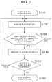
As illustrated in FIG. 2, the ECU 60 controls the fuel cell vehicle 100 as a whole. That is, when external power feeding starts (S110), the ECU 60 monitors the state of the fuel cell 20 (S120). The state of the fuel cell 20 is understood, for example, by measuring the internal temperature or the ambient temperature of the fuel cell 20 with a temperature sensor not illustrated. Such an ECU 60, which monitors the state of the fuel cell 20, can expect whether the fuel cell is in the state or not that causes deterioration of the fuel cell 20 or a failure in the driving device (e.g., the pump 22 or the compressor 24) to supply fuel to the fuel cell 20 during external power feeding (S130).
If the ECU 60 expects that the fuel cell is in the state that causes deterioration of the fuel cell 20 or a failure in the driving device to supply fuel to the fuel cell 20 (S130/YES), warning is issued toward the outside of the vehicle 10 before the fuel cell 20 stops power generation (S140).
The state that may cause deterioration of the fuel cell 20 or a failure in the driving device can be determined by whether the state of the fuel cell exceeds or not a limiting point that is a threshold by which determination can be made that deterioration occurs in the fuel cell 20 or a failure occurs in the driving device. Such a limiting point can be set, for example, as an output control starting temperature T′ for the fuel cell 20 as illustrated in FIG. 3. If the internal temperature or the ambient temperature of the fuel cell 20 exceeds the output control starting temperature T′ in FIG. 3 due to continuous operation of the fuel cell system in a high-load state, the fuel cell 20 cannot keep the amount of power generation constant, and so output limiting power P that specifies the upper limit of the electricity generated from the fuel cell 20 will be reduced. If the output limiting power P is further reduced to fall below a predetermined threshold Pth, then the output voltage FCV of the fuel cell 20 reaches voltage for shutdown, and then the fuel cell 20 stops power generation. The ECU 60 refers to a relational table or a relational expression that is a record of a relationship between the fuel cell temperature T and the output limiting value P corresponding to FIG. 3 while receiving, as an input value, the internal temperature or the environmental temperature of the fuel cell 20 that is measured by a temperature sensor not illustrated, and makes a comparison with a limiting point (in the example of FIG. 3, output control starting temperature T′). Then, warning is issued to the outside of the vehicle 10 before the output voltage FCV of the fuel cell 20 reaches a threshold for shutdown and at the stage where the internal temperature or the environmental temperature of the fuel cell 20 exceeds the output control starting temperature T′ that is a limiting point.
Warning to the outside of the vehicle 10 can be issued by the auxiliary device 70 that is controlled by the ECU 60, for example. Specifically, warning is preferably issued by a horn or a lamp. This is because a user who is outside of the vehicle can be informed of a high-load state easily by sounds or light. Since warning is issued by the auxiliary device 70 under the control of the ECU 60 that is necessary for external power feeding during external power feeding, there is no need to provide another ECU for warning separately. On the other hand, when the ECU 60 does not expect a failure or deterioration of the fuel cell, or a failure of the driving device (S130: NO), monitoring of the fuel cell by the ECU 60 will be continued.
For instance, when the auxiliary device 70 is a lamp, the lamp may be controlled so as to turn on or blink, whereby overload of external power feeding can be notified. When the auxiliary device 70 is a horn, the horn may emit a sound continuously or intermittently, whereby overload of external power feeding can be notified. When the auxiliary device 70 is an external meter, reaching to the overload range may be displayed on the external meter, whereby overload of external power feeding can be notified. Warning may be issued by these plurality of auxiliary devices operating in parallel.
The mode of warning by the auxiliary device 70 may be changed in accordance with the state of the fuel cell 20. For instance, if the temperature of the fuel cell 20 exceeds the output control starting temperature T′ in FIG. 3, then warning is issued by a lamp, and then if the temperature of the fuel cell 20 exceeds the temperature for FCV shutdown or the output limiting value P of the fuel cell 20 falls below the threshold Pth without any countermeasure such as load reduction for external power feeding being carried out, then warning is issued by a horn as well. Such a change in mode of the warning by the auxiliary device 70 enables notification of the degree of urgency of the state.
After issuance of the warning toward the outside of the vehicle 10, when external power feeding is to be continued (S150: YES), then the procedure returns back to S120 again, and the state monitoring of the fuel cell 20 is repeated (S130 to S140). On the other hand, when external power feeding is stopped (S150: NO), the processing ends (S160).
As is obvious from the flowchart of FIG. 2, even when warning is issued to the outside of the vehicle because the state of the fuel cell exceeds the limiting point for deterioration of the fuel cell 20 or a failure of the driving device (S130: YES) (S140), if the state of the fuel cell 20 returns to the limiting point or lower (S130: NO) during the following continuous external power feeding (S150: YES), then the warning toward the outside of the vehicle stops. Through such processing, a user who is outside of the vehicle can be informed that the fuel cell 20 can escape the overload state again because of countermeasures such as suspending of external power feeding or reducing of the amount of power generation after the notification of an overload state by warning. Then the external power feeding can be continued without interruption.
As described above, the method for controlling a fuel cell vehicle of the first embodiment has the following excellent advantageous effect. That is, the ECU 60 issues warning to the outside of the vehicle 10 before the fuel cell 20 stops power generation. Such warning to the outside of the vehicle 10 is issued by the auxiliary device 70 under the control of the ECU 60 of the fuel cell vehicle 100. A user who is outside of the vehicle 10 therefore can be informed by the warning from the auxiliary device 70 of the possibility that the fuel cell 20 stops power generation and so external power feeding is interrupted. The user can perform processing, such as reducing power requested to the external power-feeding device 50 or reducing load before external power feeding stops, whereby unexpected stopping of power feeding can be avoided.
Second Embodiment
Next referring to FIGS. 4 and 5, the following describes a fuel cell vehicle, to which a method for controlling fuel cell vehicles according to the second embodiment of the present invention is applied. FIG. 4 schematically illustrates a fuel cell vehicle, to which a method for controlling fuel cell vehicles according to the second embodiment of the present invention is applied. FIG. 5 is to explain the method for controlling a fuel cell vehicle according to the second embodiment.
Although the first embodiment as stated above issues warning to the outside by the auxiliary device 70 of the fuel cell vehicle 100, the method for controlling fuel cell vehicles according to the second embodiment issues warning to the outside of the vehicle 10 through rotation of a fan 81 of a radiator 80 of the fuel cell vehicle 100 as illustrated in FIG. 4. The fan 81 of the radiator 80 is electrically connected to the ECU 60 that controls the fuel cell 20. The second embodiment therefore does not have to activate or control an ECU for warning to auxiliary devices separately.
Specifically as illustrated in FIG. 5, the rotation of the fan 81 of the radiator 80 is hunting-controlled 82 so that high-speed rotation and low-speed rotation are repeated, before power generation from the fuel cell 20 stops, whereby the rotating sound of the fan 81 is changed intermittently. Warning can be issued to a user who is outside of the vehicle 10 through such a change of the rotating sound of the fan 81.
The mode of warning by controlling the rotation of the fan 81 may be changed in accordance with the state of the fuel cell 20. For instance, hunting of the rotation of the fan 81 is performed with a relatively long period if the temperature of the fuel cell 20 exceeds the output control starting temperature T′ in FIG. 3. Then, hunting of the rotation of the fan 81 is performed with a relatively short period if the temperature of the fuel cell 20 exceeds the FCV shutdown temperature or the output limiting value P of the fuel cell 20 falls below the threshold Pth temperature without any countermeasure such as load reduction for external power feeding being carried out. Such a change in mode of the warning by the hunting of the rotation of the fan 81 enables notification of the degree of urgency of the state.
Further warning by the auxiliary device 70 according to the first embodiment as stated above and warning by the rotation of the fan 81 may be combined. For instance, hunting of the rotation of the fan 81 is started if the temperature of the fuel cell 20 exceeds the output control starting temperature T′ in FIG. 3. Then if the temperature of the fuel cell 20 exceeds the FCV shutdown temperature or the output limiting value P of the fuel cell 20 falls below the threshold Pth temperature without any countermeasure such as load reduction for external power feeding being carried out, then warning by the auxiliary device 70 also is issued additionally. Such a change in mode of the warning by combining the warning by the fan 81 and the warning by the auxiliary device 70 enables notification of the degree of urgency of the state.
The method for controlling fuel cell vehicles according to the second embodiment basically has a similar advantageous effect to that of the method for controlling fuel cell vehicles according to the first embodiment. Especially according to the method for controlling fuel cell vehicles of the second embodiment, warning is issued by an auxiliary device that is used during external power feeding, and therefore this embodiment has an advantageous effect that there is no need to drive an auxiliary device separately that does not directly relate to external power feeding.
Other Embodiments
That is a description of the present invention by way of the embodiments, and it should not be understood that the description and the drawings that form a part of this disclosure limit the present invention. Various alternative embodiments, examples, and operational techniques should be apparent for those skilled in the art from this disclosure. For instance, although warning is issued by a single auxiliary device in the embodiments as stated above, warning may be issued by combining a plurality of auxiliary devices. In this way, it should be understood that the present invention encompasses various embodiments that are not described here.
  • 10 vehicle
  • 20 fuel cell
  • 22 pump
  • 24 compressor
  • 50 external power-feeding device
  • 60 electronic control unit (ECU)
  • 70 auxiliary device
  • 80 radiator
  • 81 fan
  • 100 fuel cell vehicle

Claims (10)

What is claimed is:
1. A method for controlling a fuel cell vehicle including a circuit that feeds an electric power produced by a fuel cell to outside of the fuel cell vehicle, comprising:
determining, using an electronic control unit configured to monitor a state of the fuel cell, that the state of the fuel cell exceeds a threshold value indicative of deterioration of the fuel cell or a failure of a pump or compressor that supplies fuel to the fuel cell occurs during external power feeding, and
issuing an audio or visual warning, using the electronic control unit, that is detectable by a user outside of the vehicle, based on the determination, before the fuel cell stops power generation, wherein a mode of the warning is changed in accordance with the state of the fuel cell, with a visual warning being issued by a lamp if a temperature of the fuel cell exceeds a first threshold temperature, and an audio warning being issued by a horn if the temperature of the fuel cell exceeds a second threshold temperature greater than the first threshold temperature.
2. The method for controlling a fuel cell vehicle according to claim 1, wherein the warning is issued by an auxiliary device that is controlled by the electronic control unit of the fuel cell.
3. The method for controlling a fuel cell vehicle according to claim 1, wherein the warning is issued, using the electronic control unit, by the horn and the lamp of the fuel cell vehicle.
4. The method for controlling a fuel cell vehicle according to claim 1, wherein the warning is further issued, using the electronic control unit, through rotation of a fan of a radiator of the fuel cell vehicle.
5. The method for controlling a fuel cell vehicle according to claim 1, wherein when it is determined, using the electronic control unit, that the state of the fuel cell returns to the threshold value or lower after issuance of the warning, issuance of the warning is stopped.
6. A fuel cell vehicle, comprising:
a fuel cell;
a pump or compressor that supplies fuel to the fuel cell;
a circuit that feeds an electric power produced by the fuel cell to outside of the fuel cell vehicle; and
an electronic control unit programmed to:
determine that a state of the fuel cell exceeds a threshold value indicative of deterioration of the fuel cell or the pump or compressor fails during external power feeding, and
issue an audio or visual warning, using the electronic control unit, that is detectable by a user outside of the vehicle, based on the determination, before the fuel cell stops power generation, wherein a mode of the warning is changed in accordance with the state of the fuel cell, with a visual warning being issued by a lamp if a temperature of the fuel cell exceeds a first threshold temperature, and an audio warning being issued by a horn if the temperature of the fuel cell exceeds a second threshold temperature greater than the first threshold temperature.
7. The fuel cell vehicle according to claim 6, further comprising an auxiliary device for the fuel cell, wherein the electronic control unit is programmed to perform issuing the warning by controlling the auxiliary device.
8. The fuel cell vehicle according to claim 6, wherein the electronic control unit is programmed to perform issuing the warning by controlling the horn and the lamp.
9. The fuel cell vehicle according to claim 6, further comprising a radiator, wherein the electronic control unit is further programmed to perform issuing the warning by controlling rotation of a fan of the radiator.
10. The fuel cell vehicle according to claim 6, wherein the electronic control unit is programmed to further perform, when it is determined, using the electronic control unit, that the state of the fuel cell returns to the threshold value or lower after issuance of the warning, stopping issuance of the warning.
US14/938,117 2014-11-12 2015-11-11 Method for controlling fuel cell vehicles and fuel cell vehicles Active US10744903B2 (en)

Priority Applications (1)

Application Number Priority Date Filing Date Title
US16/899,267 US11491893B2 (en) 2014-11-12 2020-06-11 Method for controlling fuel cell vehicles and fuel cell vehicles

Applications Claiming Priority (2)

Application Number Priority Date Filing Date Title
JP2014-230189 2014-11-12
JP2014230189A JP6136022B2 (en) 2014-11-12 2014-11-12 Control method of fuel cell vehicle

Related Child Applications (1)

Application Number Title Priority Date Filing Date
US16/899,267 Continuation US11491893B2 (en) 2014-11-12 2020-06-11 Method for controlling fuel cell vehicles and fuel cell vehicles

Publications (2)

Publication Number Publication Date
US20160129807A1 US20160129807A1 (en) 2016-05-12
US10744903B2 true US10744903B2 (en) 2020-08-18

Family

ID=55803546

Family Applications (2)

Application Number Title Priority Date Filing Date
US14/938,117 Active US10744903B2 (en) 2014-11-12 2015-11-11 Method for controlling fuel cell vehicles and fuel cell vehicles
US16/899,267 Active 2036-03-09 US11491893B2 (en) 2014-11-12 2020-06-11 Method for controlling fuel cell vehicles and fuel cell vehicles

Family Applications After (1)

Application Number Title Priority Date Filing Date
US16/899,267 Active 2036-03-09 US11491893B2 (en) 2014-11-12 2020-06-11 Method for controlling fuel cell vehicles and fuel cell vehicles

Country Status (6)

Country Link
US (2) US10744903B2 (en)
JP (1) JP6136022B2 (en)
KR (1) KR20160056788A (en)
CN (1) CN105584379B (en)
CA (1) CA2911084C (en)
DE (1) DE102015118800B4 (en)

Families Citing this family (3)

* Cited by examiner, † Cited by third party
Publication number Priority date Publication date Assignee Title
JP6743774B2 (en) * 2017-06-29 2020-08-19 トヨタ自動車株式会社 Fuel cell system
US10000152B1 (en) 2017-07-07 2018-06-19 Advanced Sonic Alert Technologies, LLC External audio alert system and method for vehicular use
CN112092682B (en) * 2019-06-17 2022-03-15 广州汽车集团股份有限公司 Fuel cell control method and device

Citations (26)

* Cited by examiner, † Cited by third party
Publication number Priority date Publication date Assignee Title
JP2002033110A (en) 2000-07-18 2002-01-31 Honda Motor Co Ltd Gas supply device for fuel cell
US20030039869A1 (en) * 2001-07-27 2003-02-27 Honda Giken Kogyo Kabushiki Kaisha Method for detecting abnormality in fuel cell
US20040062963A1 (en) * 2002-09-26 2004-04-01 Toyota Jidosha Kabushiki Kaisha Alert method relating to remaining fuel amount of fuel cell system and fuel cell system using the same
JP2004158333A (en) 2002-11-07 2004-06-03 Nissan Motor Co Ltd Fuel cell system
US20040221641A1 (en) * 2003-05-09 2004-11-11 Denso Corporation And Nippon Soken, Inc. Fault detecting apparatus designed to detect different types of faults of gas sensor
US20040229097A1 (en) * 2003-05-15 2004-11-18 Toyota Jidosha Kabushiki Kaisha Fuel cell system and associated operation method
US20060032547A1 (en) * 2004-08-11 2006-02-16 Rossi Marc A Spontaneous full fuel tank indicator
US20060220819A1 (en) * 2003-12-24 2006-10-05 Nattel Group, Inc. Method for intelligent crescendo system
US20070031709A1 (en) * 2005-07-29 2007-02-08 Canon Kabushiki Kaisha Electronic apparatus and fuel cell control method for electronic apparatus
US20070172708A1 (en) * 2004-03-12 2007-07-26 Yasuo Takebe Fuel cell system failure diagnosis method, failure diagnosis device using same, and fuel cell system
DE102007050797A1 (en) * 2007-10-24 2008-07-24 Daimler Ag Method for operating fuel cell system, involves arranging electric motor driven compressor in fuel cell cycle and regulating system is used for protection of pump of compressor
JP2009081991A (en) 2004-03-10 2009-04-16 Fujitsu Ten Ltd Own-vehicle existence informing device
US20110008687A1 (en) * 2009-07-08 2011-01-13 Bloom Energy Corporation Fuel cell system with quick connect components
US20110298422A1 (en) 2010-06-02 2011-12-08 Bryan Marc Failing Energy transfer with vehicles
JP2012016197A (en) 2010-07-01 2012-01-19 Honda Motor Co Ltd External power feeding device and electric vehicle
WO2012026052A1 (en) 2010-08-23 2012-03-01 パナソニック株式会社 Method for determining degradation in fuel cell
US20120191365A1 (en) 2009-10-29 2012-07-26 Hoya Corporation Auxiliary diagnostic apparatus and auxiliary diagnostic method
KR20120099869A (en) 2011-03-02 2012-09-12 이엔테크놀로지 주식회사 Apparatus for electric car charging and method for charging situation notification using the apparatus
JP2013198290A (en) 2012-03-19 2013-09-30 Honda Motor Co Ltd Power supply system
JP2013198292A (en) 2012-03-19 2013-09-30 Honda Motor Co Ltd Power supply system
US20140080024A1 (en) * 2012-09-18 2014-03-20 Honda Motor Co., Ltd. Electric power supply system
US20140176325A1 (en) * 2012-12-20 2014-06-26 Hyundai Autron Co., Ltd. Electric vehicle and control method thereof
US20140220470A1 (en) * 2011-08-22 2014-08-07 Nissan Motor Co., Ltd. Fuel cell system
US20140320163A1 (en) * 2011-12-09 2014-10-30 Daimler Ag Method for monitoring a pump
US20150184804A1 (en) * 2013-12-26 2015-07-02 Honda Motor Co., Ltd. Control method for fuel filling system
US20160335815A1 (en) * 2015-05-14 2016-11-17 Hyundai Motor Company Method and system for maintaining stability of system of fuel cell vehicle

Family Cites Families (2)

* Cited by examiner, † Cited by third party
Publication number Priority date Publication date Assignee Title
JP2007059415A (en) * 2001-06-15 2007-03-08 Toyota Motor Corp Power output device with fuel cell and its method
JP4839697B2 (en) * 2005-06-30 2011-12-21 株式会社エクォス・リサーチ Fuel cell system

Patent Citations (31)

* Cited by examiner, † Cited by third party
Publication number Priority date Publication date Assignee Title
US20020034669A1 (en) * 2000-07-18 2002-03-21 Tomoki Kobayashi Gas-supplying apparatus for fuel cell
JP2002033110A (en) 2000-07-18 2002-01-31 Honda Motor Co Ltd Gas supply device for fuel cell
US20030039869A1 (en) * 2001-07-27 2003-02-27 Honda Giken Kogyo Kabushiki Kaisha Method for detecting abnormality in fuel cell
US20040062963A1 (en) * 2002-09-26 2004-04-01 Toyota Jidosha Kabushiki Kaisha Alert method relating to remaining fuel amount of fuel cell system and fuel cell system using the same
US20050181246A1 (en) 2002-11-07 2005-08-18 Nissan Motor Co., Ltd. Fuel cell system and related method
JP2004158333A (en) 2002-11-07 2004-06-03 Nissan Motor Co Ltd Fuel cell system
US20040221641A1 (en) * 2003-05-09 2004-11-11 Denso Corporation And Nippon Soken, Inc. Fault detecting apparatus designed to detect different types of faults of gas sensor
US20040229097A1 (en) * 2003-05-15 2004-11-18 Toyota Jidosha Kabushiki Kaisha Fuel cell system and associated operation method
US20060220819A1 (en) * 2003-12-24 2006-10-05 Nattel Group, Inc. Method for intelligent crescendo system
JP2009081991A (en) 2004-03-10 2009-04-16 Fujitsu Ten Ltd Own-vehicle existence informing device
US20070172708A1 (en) * 2004-03-12 2007-07-26 Yasuo Takebe Fuel cell system failure diagnosis method, failure diagnosis device using same, and fuel cell system
US20060032547A1 (en) * 2004-08-11 2006-02-16 Rossi Marc A Spontaneous full fuel tank indicator
US20070031709A1 (en) * 2005-07-29 2007-02-08 Canon Kabushiki Kaisha Electronic apparatus and fuel cell control method for electronic apparatus
DE102007050797A1 (en) * 2007-10-24 2008-07-24 Daimler Ag Method for operating fuel cell system, involves arranging electric motor driven compressor in fuel cell cycle and regulating system is used for protection of pump of compressor
US20110008687A1 (en) * 2009-07-08 2011-01-13 Bloom Energy Corporation Fuel cell system with quick connect components
US20120191365A1 (en) 2009-10-29 2012-07-26 Hoya Corporation Auxiliary diagnostic apparatus and auxiliary diagnostic method
US20110298422A1 (en) 2010-06-02 2011-12-08 Bryan Marc Failing Energy transfer with vehicles
JP2012016197A (en) 2010-07-01 2012-01-19 Honda Motor Co Ltd External power feeding device and electric vehicle
JPWO2012026052A1 (en) 2010-08-23 2013-10-28 パナソニック株式会社 Degradation judgment method of fuel cell
US20120191385A1 (en) * 2010-08-23 2012-07-26 Masaki Mitsui Method for determining deterioration of fuel cell
WO2012026052A1 (en) 2010-08-23 2012-03-01 パナソニック株式会社 Method for determining degradation in fuel cell
KR20120099869A (en) 2011-03-02 2012-09-12 이엔테크놀로지 주식회사 Apparatus for electric car charging and method for charging situation notification using the apparatus
US20140220470A1 (en) * 2011-08-22 2014-08-07 Nissan Motor Co., Ltd. Fuel cell system
US20140320163A1 (en) * 2011-12-09 2014-10-30 Daimler Ag Method for monitoring a pump
JP2013198290A (en) 2012-03-19 2013-09-30 Honda Motor Co Ltd Power supply system
JP2013198292A (en) 2012-03-19 2013-09-30 Honda Motor Co Ltd Power supply system
US20140080024A1 (en) * 2012-09-18 2014-03-20 Honda Motor Co., Ltd. Electric power supply system
JP2014060068A (en) 2012-09-18 2014-04-03 Honda Motor Co Ltd Power supply system
US20140176325A1 (en) * 2012-12-20 2014-06-26 Hyundai Autron Co., Ltd. Electric vehicle and control method thereof
US20150184804A1 (en) * 2013-12-26 2015-07-02 Honda Motor Co., Ltd. Control method for fuel filling system
US20160335815A1 (en) * 2015-05-14 2016-11-17 Hyundai Motor Company Method and system for maintaining stability of system of fuel cell vehicle

Non-Patent Citations (3)

* Cited by examiner, † Cited by third party
Title
JP2013198292_translated.pdf. Translation of JP 2013-198292 from ESPACENET obtained on Dec. 20, 2016. *
Translation of DE102007050797 obtained via ESPACENET on Oct. 4, 2019. (Year: 2008). *
Translation of KR101231913 obtained via ESPACENET on Jun. 19, 2018 (Year: 2012). *

Also Published As

Publication number Publication date
DE102015118800B4 (en) 2022-04-28
US11491893B2 (en) 2022-11-08
CA2911084A1 (en) 2016-05-12
JP2016096619A (en) 2016-05-26
CA2911084C (en) 2018-02-27
US20160129807A1 (en) 2016-05-12
CN105584379B (en) 2018-01-23
JP6136022B2 (en) 2017-05-31
US20200298729A1 (en) 2020-09-24
DE102015118800A1 (en) 2016-05-12
CN105584379A (en) 2016-05-18
KR20160056788A (en) 2016-05-20

Similar Documents

Publication Publication Date Title
US11491893B2 (en) Method for controlling fuel cell vehicles and fuel cell vehicles
US8445153B2 (en) Fuel cell high-potential prevention control system
US8277993B2 (en) Fuel cell system
US10096853B2 (en) Method of detecting abnormality in pressure sensor and fuel cell system
EP2800183A1 (en) Fuel cell system
CN107452972B (en) Fuel cell system and control method thereof
US10099573B2 (en) Drive system and vehicle
JP5786952B2 (en) Fuel cell output control device
KR102211693B1 (en) Fuel cell system
US9437889B2 (en) Powering a fuel cell stack during standby
JP6988605B2 (en) Fuel cell system
US10218019B2 (en) Method of determining hydrogen deficiency and device for determining hydrogen deficiency
US8642222B2 (en) Fuel cell power request control strategy
CA2911568C (en) Fuel cell system and scavenging treatment control method
JP2016091810A (en) Fuel cell system and maximum power calculation method
US11456471B2 (en) Fuel cell system and method of controlling fuel cell system
JP2010003444A (en) Fuel cell vehicle
US20110053015A1 (en) Control Method for a Fuel Cell System and Fuel Cell System
JP5167026B2 (en) Fuel cell system
JP2017224576A (en) Fuel cell system
JP2016072191A (en) Fuel battery system
US20220320538A1 (en) Fuel cell power system
JP5800279B2 (en) Fuel cell system and control method thereof
JP2011204361A (en) Control method of fuel cell system
JP2017224575A (en) Fuel cell system

Legal Events

Date Code Title Description
AS Assignment

Owner name: TOYOTA JIDOSHA KABUSHIKI KAISHA, JAPAN

Free format text: ASSIGNMENT OF ASSIGNORS INTEREST;ASSIGNORS:OKAMOTO, YOHEI;IMANISHI, HIROYUKI;NADA, MITSUHIRO;AND OTHERS;SIGNING DATES FROM 20150928 TO 20150929;REEL/FRAME:037013/0052

STPP Information on status: patent application and granting procedure in general

Free format text: NON FINAL ACTION MAILED

STPP Information on status: patent application and granting procedure in general

Free format text: RESPONSE TO NON-FINAL OFFICE ACTION ENTERED AND FORWARDED TO EXAMINER

STPP Information on status: patent application and granting procedure in general

Free format text: FINAL REJECTION MAILED

STPP Information on status: patent application and granting procedure in general

Free format text: RESPONSE AFTER FINAL ACTION FORWARDED TO EXAMINER

STPP Information on status: patent application and granting procedure in general

Free format text: DOCKETED NEW CASE - READY FOR EXAMINATION

STPP Information on status: patent application and granting procedure in general

Free format text: NON FINAL ACTION MAILED

STPP Information on status: patent application and granting procedure in general

Free format text: NOTICE OF ALLOWANCE MAILED -- APPLICATION RECEIVED IN OFFICE OF PUBLICATIONS

STCF Information on status: patent grant

Free format text: PATENTED CASE

MAFP Maintenance fee payment

Free format text: PAYMENT OF MAINTENANCE FEE, 4TH YEAR, LARGE ENTITY (ORIGINAL EVENT CODE: M1551); ENTITY STATUS OF PATENT OWNER: LARGE ENTITY

Year of fee payment: 4