US10742159B2 - Plate for installing photovoltaic panels - Google Patents
Plate for installing photovoltaic panels Download PDFInfo
- Publication number
- US10742159B2 US10742159B2 US15/262,341 US201615262341A US10742159B2 US 10742159 B2 US10742159 B2 US 10742159B2 US 201615262341 A US201615262341 A US 201615262341A US 10742159 B2 US10742159 B2 US 10742159B2
- Authority
- US
- United States
- Prior art keywords
- support plate
- photovoltaic panel
- roof
- support
- pads
- Prior art date
- Legal status (The legal status is an assumption and is not a legal conclusion. Google has not performed a legal analysis and makes no representation as to the accuracy of the status listed.)
- Active
Links
- XLYOFNOQVPJJNP-UHFFFAOYSA-N water Substances O XLYOFNOQVPJJNP-UHFFFAOYSA-N 0.000 claims abstract description 22
- 230000002787 reinforcement Effects 0.000 claims abstract description 14
- 238000005553 drilling Methods 0.000 claims abstract description 12
- 239000011324 bead Substances 0.000 claims description 9
- 230000010354 integration Effects 0.000 claims description 7
- 238000011144 upstream manufacturing Methods 0.000 claims description 5
- 238000011010 flushing procedure Methods 0.000 claims description 3
- 238000005259 measurement Methods 0.000 claims 1
- 230000008595 infiltration Effects 0.000 description 2
- 238000001764 infiltration Methods 0.000 description 2
- 238000009434 installation Methods 0.000 description 2
- 230000035515 penetration Effects 0.000 description 2
- 230000014509 gene expression Effects 0.000 description 1
- 230000005484 gravity Effects 0.000 description 1
- 238000001746 injection moulding Methods 0.000 description 1
- 238000004519 manufacturing process Methods 0.000 description 1
- 238000000465 moulding Methods 0.000 description 1
- 239000000126 substance Substances 0.000 description 1
Images


Classifications
-
- H—ELECTRICITY
- H02—GENERATION; CONVERSION OR DISTRIBUTION OF ELECTRIC POWER
- H02S—GENERATION OF ELECTRIC POWER BY CONVERSION OF INFRARED RADIATION, VISIBLE LIGHT OR ULTRAVIOLET LIGHT, e.g. USING PHOTOVOLTAIC [PV] MODULES
- H02S20/00—Supporting structures for PV modules
- H02S20/20—Supporting structures directly fixed to an immovable object
- H02S20/22—Supporting structures directly fixed to an immovable object specially adapted for buildings
- H02S20/23—Supporting structures directly fixed to an immovable object specially adapted for buildings specially adapted for roof structures
- H02S20/25—Roof tile elements
-
- H—ELECTRICITY
- H02—GENERATION; CONVERSION OR DISTRIBUTION OF ELECTRIC POWER
- H02S—GENERATION OF ELECTRIC POWER BY CONVERSION OF INFRARED RADIATION, VISIBLE LIGHT OR ULTRAVIOLET LIGHT, e.g. USING PHOTOVOLTAIC [PV] MODULES
- H02S30/00—Structural details of PV modules other than those related to light conversion
- H02S30/10—Frame structures
-
- Y—GENERAL TAGGING OF NEW TECHNOLOGICAL DEVELOPMENTS; GENERAL TAGGING OF CROSS-SECTIONAL TECHNOLOGIES SPANNING OVER SEVERAL SECTIONS OF THE IPC; TECHNICAL SUBJECTS COVERED BY FORMER USPC CROSS-REFERENCE ART COLLECTIONS [XRACs] AND DIGESTS
- Y02—TECHNOLOGIES OR APPLICATIONS FOR MITIGATION OR ADAPTATION AGAINST CLIMATE CHANGE
- Y02B—CLIMATE CHANGE MITIGATION TECHNOLOGIES RELATED TO BUILDINGS, e.g. HOUSING, HOUSE APPLIANCES OR RELATED END-USER APPLICATIONS
- Y02B10/00—Integration of renewable energy sources in buildings
- Y02B10/10—Photovoltaic [PV]
-
- Y02B10/12—
-
- Y—GENERAL TAGGING OF NEW TECHNOLOGICAL DEVELOPMENTS; GENERAL TAGGING OF CROSS-SECTIONAL TECHNOLOGIES SPANNING OVER SEVERAL SECTIONS OF THE IPC; TECHNICAL SUBJECTS COVERED BY FORMER USPC CROSS-REFERENCE ART COLLECTIONS [XRACs] AND DIGESTS
- Y02—TECHNOLOGIES OR APPLICATIONS FOR MITIGATION OR ADAPTATION AGAINST CLIMATE CHANGE
- Y02E—REDUCTION OF GREENHOUSE GAS [GHG] EMISSIONS, RELATED TO ENERGY GENERATION, TRANSMISSION OR DISTRIBUTION
- Y02E10/00—Energy generation through renewable energy sources
- Y02E10/50—Photovoltaic [PV] energy
Definitions
- the present disclosure concerns a plate for installing photovoltaic panels that allows for a tight, simple, and rapid installation
- This support plate is adapted to fit in a photovoltaic panel and enable fastening and integration of this panel on a building roof/roofing.
- the plate has tight vertical overlapping arrangement, tight lateral fitting arrangement, points for fastening the plate, and an empty space intended for the passage of cables and for access to the framework of the roof.
- the present disclosure relates to a support plate adapted to fit in a photovoltaic panel and enable fastening and integration of this panel on a building roof, comprising:
- a plurality of guide rails that are arranged upstream of the empty space along the flow direction of the water coming from the ridge of the roof, and which are generally arranged in an inverted V shape so as to divert the flow of the water on the lateral sides of the empty space,
- At least one reinforcement which is interposed between the lateral fitting arrangement and the roof and which is designed so as to prevent crushing of said fitting arrangement
- At least one drilling area which is arranged in the vicinity of each support pad and which is raised so as to avoid the penetration of water
- a graduation that is designed so as to adjust the vertical overlap between two juxtaposed plates.
- each guide rail forms a bead for diverting the flow of the water on the lateral sides of the empty space.
- the fitting presents a hollow section generally formed in an inverted U shape, and the reinforcement is an affixed part which is arranged in the recess delimited by the fitting.
- the reinforcement allows resisting the crushing efforts exerted on the fitting so as to preserve the tightness of the plate.
- the plate comprises a bead disposed so as to avoid the flow of the water coming from the ridge of the roof in the empty space.
- a groove is formed in said bead, enabling the passage of cables between the plate and the photovoltaic panel.
- each drilling area is raised lesser than the associated support pad so as to enable the arrangement of fastening device.
- the support plate comprises means for lifting and ventilating said photovoltaic panel, and wedges allowing flushing the water coming from the ridge of said roof.
- the present disclosure also concerns a set formed by a photovoltaic panel and a plate in accordance with the foregoing fitted in this photovoltaic panel.
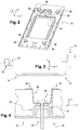
- FIG. 1 is a top view which illustrates the support plate according to the present disclosure in the portrait format
- FIG. 2 is a perspective view which illustrates the support plate of FIG. 1 ;
- FIG. 3 is a side view which illustrates the tight lateral fitting arrangement of the support plate.
- FIG. 4 is a cross-sectional detail view, which illustrates a reinforcement of the lateral fitting arrangement.
- upstream and downstream should be understood with reference to the slope of the roof on which the plate is intended to be mounted and to the flow direction of the runoff water.
- FIG. 1 there is represented a support plate 10 adapted to fit in a photovoltaic panel (not represented) and enable fastening and integration of this panel on a building roof.
- the plate 10 includes a tight vertical overlapping arrangement 12 and tight lateral fitting arrangement 14 .
- the vertical overlapping arrangement 12 are formed by a transverse upper strip 16 and by a transverse lower strip 18 which are adapted to enable overlapping of an upper support plate and of a lower support plate vertically juxtaposed.
- the lower strip 18 of the upper plate 10 covers the upper strip 16 of the lower plate 10 so as to ensure a perfect tightness.
- the overlapping arrangement are provided with a graduation 20 which is designed so as to adjust the vertical overlap and the coverage between two juxtaposed plates.
- the graduation represents for example a graduated measuring scale, which is engraved, printed or molded on the upper strip 16 of the support plate 10 .
- the graduation 20 allows measuring the overlap of two support plates 10 and providing a low coverage and a good tightness.
- the graduation 20 allows setting the overlap of two juxtaposed support plates 10 based on the dimension of the photovoltaic panel to be installed, so that the support plates can adapt to different formats of photovoltaic panels.
- the lateral fitting arrangement 14 comprise a first profile 22 and a second profile 24 , each extending vertically on the sides of the plate 10 and each presenting a hollow section generally formed in an inverted U shape.
- the first profile 22 presents a shape adapted to fit in the recess formed by the second profile 24 , when two adjacent support plates 10 are juxtaposed transversely, so as to ensure a good tightness between the plates.
- a clip 26 is fastened on the profiles 22 , 24 by means of a screw 28 .
- the clip 26 includes a first retaining leg 30 which is adapted to cooperate with a photovoltaic panel carried by a first plate 10 , and a second retaining leg 32 which is adapted to cooperate with a photovoltaic panel carried by a second plate 10 .
- the panels can transmit a compressive effort with a vertical component on the fitting arrangement 14 .
- the support plate 10 is equipped with a reinforcement 34 which is interposed between the lateral fitting arrangement 14 and the roof.
- a crushing of the fitting arrangement 14 is to be avoided because it would risk opening a passage for water infiltration, for example by deformation of the hole intended for the passage of the screw 28 , or by a rise of the second profile 24 .
- the reinforcement 34 is an affixed part which is arranged in the recess delimited by the first profile 22 of the fitting arrangement 14 so as to resist crushing of the fitting arrangement 14 .
- the reinforcement 34 may also be integrated and formed by the first profile 22 , for example during the molding of the first profile 22 .
- the support plate 10 includes pads 36 for supporting the photovoltaic panel which are lifted so as to raise the photovoltaic panel.
- the support pads 36 allow the positioning, the guidance, the wedging of the photovoltaic panel and the support of the feet of the mounters of the panels.
- each support pad 36 is associated to a drilling area 38 which is arranged downstream of the support pads 36 in order to be protected from the water flow and which is raised so as to avoid the penetration of water.
- drilling area 38 is meant an area which is designed so as to enable the drilling and the passage of fastening device.
- the drilling area 38 may include an imprint or a mark indicating a drilling location, and/or an area mechanically pre-weakened in order to facilitate drilling, for example.
- each drilling area 38 is raised lesser than the associated support pad 36 so as to enable the arrangement of fastening device, such as screws (not represented), without these fastening device surpassing the associated support pad 36 in order not to hinder the set-up of the photovoltaic panel.
- the support plate 10 delimits an empty space 40 intended for the passage of cables and for access to the framework of the roof.
- the empty space 40 is surmounted by a bead 42 which is disposed so as to avoid the flow of the water coming from the ridge of the roof in the empty space 40 .
- a groove 44 is formed in the bead 42 , allowing the passage of cables between the plate 10 and the photovoltaic panel.
- the plate 10 comprises a plurality of guide rails 46 which are arranged upstream of the empty space 40 along the flow direction of the water coming from the ridge of the roof, and which are generally arranged in an inverted V shape so as to divert the flow of the water on the lateral sides of the empty space 40 .
- Each guide rail 46 forms a lifted bead for diverting the flow of the water on the lateral sides of the empty space 40 .
- the plate 10 comprises means 50 for lifting the photovoltaic panel which allow ventilating the photovoltaic panel.
- the plate 10 is equipped with wedges 52 which are arranged upstream of the support pads 36 , and which allow flushing the water coming from the ridge of the roof.
- the wedges 52 are designed so as to support the photovoltaic panel.
- the plate 10 is formed in one single piece, with the possible exception of the reinforcement 34 , in one form by injection molding, or by stamping or by any other manufacturing method.
- the plate 10 may also be designed and sized so as to enable mounting in a landscape fashion. Such variations are not to be regarded as a departure from the spirit and scope of the disclosure.
Abstract
Description
Claims (17)
Applications Claiming Priority (4)
| Application Number | Priority Date | Filing Date | Title |
|---|---|---|---|
| FR1451949 | 2014-03-10 | ||
| FR14/51949 | 2014-03-10 | ||
| FR1451949A FR3018406B1 (en) | 2014-03-10 | 2014-03-10 | IMPROVED PLATE FOR THE INSTALLATION OF PHOTOVOLTAIC PANELS |
| PCT/FR2015/050595 WO2015136215A1 (en) | 2014-03-10 | 2015-03-10 | Improved plate for installing photovoltaic panels |
Related Parent Applications (1)
| Application Number | Title | Priority Date | Filing Date |
|---|---|---|---|
| PCT/FR2015/050595 Continuation WO2015136215A1 (en) | 2014-03-10 | 2015-03-10 | Improved plate for installing photovoltaic panels |
Publications (2)
| Publication Number | Publication Date |
|---|---|
| US20170005610A1 US20170005610A1 (en) | 2017-01-05 |
| US10742159B2 true US10742159B2 (en) | 2020-08-11 |
Family
ID=50513360
Family Applications (1)
| Application Number | Title | Priority Date | Filing Date |
|---|---|---|---|
| US15/262,341 Active US10742159B2 (en) | 2014-03-10 | 2016-09-12 | Plate for installing photovoltaic panels |
Country Status (7)
| Country | Link |
|---|---|
| US (1) | US10742159B2 (en) |
| EP (1) | EP3117517B8 (en) |
| JP (1) | JP6928733B2 (en) |
| CA (1) | CA2941931C (en) |
| FR (1) | FR3018406B1 (en) |
| RU (1) | RU2681748C9 (en) |
| WO (1) | WO2015136215A1 (en) |
Families Citing this family (7)
| Publication number | Priority date | Publication date | Assignee | Title |
|---|---|---|---|---|
| DE202015000200U1 (en) * | 2015-01-16 | 2015-02-18 | Sigma Energy Systems Gmbh | Solar roof panel system |
| US10270382B2 (en) * | 2015-05-26 | 2019-04-23 | Arcelormittal | Panel, assembly of panels and associated roof |
| US10673373B2 (en) | 2016-02-12 | 2020-06-02 | Solarcity Corporation | Building integrated photovoltaic roofing assemblies and associated systems and methods |
| US10778139B2 (en) | 2016-10-27 | 2020-09-15 | Tesla, Inc. | Building integrated photovoltaic system with glass photovoltaic tiles |
| CN107070388B (en) * | 2017-02-13 | 2023-04-28 | 马倩 | Hook lock device for installing photovoltaic module |
| CN107834958B (en) * | 2017-10-16 | 2019-06-25 | 江苏美斯乐能源系统集成科技有限公司 | Roofing photovoltaic bracket |
| FR3127855B1 (en) * | 2021-10-04 | 2023-12-08 | Yaniv Douieb | Support plate for the integration of photovoltaic panels of different dimensions |
Citations (29)
| Publication number | Priority date | Publication date | Assignee | Title |
|---|---|---|---|---|
| US309134A (en) * | 1884-12-09 | Charles b | ||
| US3021927A (en) * | 1959-04-06 | 1962-02-20 | Jr John R Mckee | Lap-lox fastener |
| US3775925A (en) * | 1970-12-02 | 1973-12-04 | Fujita Kenzo Kogyo Co Ltd | Roofing panel with drainage means |
| US4204523A (en) | 1976-09-11 | 1980-05-27 | E. Cacarda Gmbh | Mount for solar collectors |
| US4406106A (en) * | 1979-04-05 | 1983-09-27 | Dinges Kenneth N | Concealed fastener panel construction and method of installation |
| JPS626047A (en) | 1985-06-29 | 1987-01-13 | 三晃金属工業株式会社 | Inlay outer fence body |
| US5287670A (en) * | 1990-10-18 | 1994-02-22 | Gantan Beauty Industry, Co., Ltd. | Double roofing roof structure |
| JPH10169131A (en) | 1996-12-13 | 1998-06-23 | Sekisui House Ltd | Device for mounting solar cell |
| US6178703B1 (en) * | 1993-10-05 | 2001-01-30 | Certainteed Corporation | Roofing tile, roof and method of assembling |
| JP2001107517A (en) | 1999-10-06 | 2001-04-17 | Sumitomo Metal Steel Products Inc | Roof covering structure, bracket metal, and roofing |
| JP2002097754A (en) | 2000-09-26 | 2002-04-05 | Sumitomo Metal Steel Products Inc | Roofing structure and retaining metal tools and roofing materials |
| US20020129849A1 (en) * | 2001-03-14 | 2002-09-19 | Steve Heckeroth | Method and apparatus for mounting a photovoltaic roofing material |
| RU2194827C2 (en) | 2001-01-24 | 2002-12-20 | Государственное унитарное предприятие "Научно-производственное объединение машиностроения" | Roof panel with solar battery |
| US20030154680A1 (en) * | 2002-02-20 | 2003-08-21 | Dinwoodie Thomas L. | Shingle assembly |
| JP2003527504A (en) | 2000-03-16 | 2003-09-16 | ローヤル エコプロダクツ カムパニー,ア ディヴィジョン オブ ローヤル グループ テクノロジーズ インク. | Plastic roof tiles |
| US20050005534A1 (en) * | 2001-09-28 | 2005-01-13 | Kaneka Corporation | Solar cell module, method of laying solar cell modules, and apparatus for preventing solar cell modules from being blown off |
| US6856496B1 (en) * | 1999-06-14 | 2005-02-15 | Powertile Ltd | Solar tile assembly |
| US20050072092A1 (en) * | 2003-10-01 | 2005-04-07 | Scott Williams | High profile composition shingles for roofs |
| US20080302030A1 (en) * | 2007-05-07 | 2008-12-11 | Robert Stancel | Structures for Low Cost, Reliable Solar Roofing |
| US20090000222A1 (en) * | 2007-06-28 | 2009-01-01 | Kalkanoglu Husnu M | Photovoltaic Roofing Tiles And Methods For Making Them |
| US20100281794A1 (en) * | 2007-10-02 | 2010-11-11 | Guy Saillard | Device for holding photovoltaic panels on a roof, including holding means allowing an air flow between a base plane and the photovoltaic panel |
| US20110162301A1 (en) * | 2008-09-10 | 2011-07-07 | Keneka Corporation | Solar Cell Module and Solar Cell Array |
| DE102011104303A1 (en) | 2011-06-03 | 2012-12-06 | Basf Se | Photovoltaic system for installation on roofs with plastic substrate and photovoltaic module |
| FR2977009A1 (en) * | 2011-06-27 | 2012-12-28 | Svh En | PLATE FOR SUPPORTING, INTEGRATING AND FIXING PHOTOVOLTAIC PANELS |
| US20130133270A1 (en) * | 2011-11-09 | 2013-05-30 | Zep Solar, Inc. | Solar Panel Attachment System |
| US8713861B2 (en) * | 2010-12-10 | 2014-05-06 | Solus Engineering, Llc | Roof tiles and related systems |
| US8869471B2 (en) * | 2011-03-01 | 2014-10-28 | Ecolibrium Solar, Inc. | Support assembly for supporting photovoltaic modules |
| US20150089887A1 (en) * | 2009-10-28 | 2015-04-02 | Carmen Bellavia | Light weight molded roof tile with integrated solar capabilities |
| US20150288327A1 (en) * | 2014-04-02 | 2015-10-08 | Sunedison Llc | Photovoltaic module integrated mounting and electronics systems |
Family Cites Families (1)
| Publication number | Priority date | Publication date | Assignee | Title |
|---|---|---|---|---|
| JP4286592B2 (en) * | 2003-06-06 | 2009-07-01 | 大成建設株式会社 | Solar cell module for tiled roof |
-
2014
- 2014-03-10 FR FR1451949A patent/FR3018406B1/en not_active Expired - Fee Related
-
2015
- 2015-03-10 JP JP2016557023A patent/JP6928733B2/en active Active
- 2015-03-10 EP EP15717541.5A patent/EP3117517B8/en active Active
- 2015-03-10 CA CA2941931A patent/CA2941931C/en active Active
- 2015-03-10 WO PCT/FR2015/050595 patent/WO2015136215A1/en active Application Filing
- 2015-03-10 RU RU2016139235A patent/RU2681748C9/en active
-
2016
- 2016-09-12 US US15/262,341 patent/US10742159B2/en active Active
Patent Citations (31)
| Publication number | Priority date | Publication date | Assignee | Title |
|---|---|---|---|---|
| US309134A (en) * | 1884-12-09 | Charles b | ||
| US3021927A (en) * | 1959-04-06 | 1962-02-20 | Jr John R Mckee | Lap-lox fastener |
| US3775925A (en) * | 1970-12-02 | 1973-12-04 | Fujita Kenzo Kogyo Co Ltd | Roofing panel with drainage means |
| US4204523A (en) | 1976-09-11 | 1980-05-27 | E. Cacarda Gmbh | Mount for solar collectors |
| US4406106A (en) * | 1979-04-05 | 1983-09-27 | Dinges Kenneth N | Concealed fastener panel construction and method of installation |
| JPS626047A (en) | 1985-06-29 | 1987-01-13 | 三晃金属工業株式会社 | Inlay outer fence body |
| US5287670A (en) * | 1990-10-18 | 1994-02-22 | Gantan Beauty Industry, Co., Ltd. | Double roofing roof structure |
| US6178703B1 (en) * | 1993-10-05 | 2001-01-30 | Certainteed Corporation | Roofing tile, roof and method of assembling |
| JPH10169131A (en) | 1996-12-13 | 1998-06-23 | Sekisui House Ltd | Device for mounting solar cell |
| US6856496B1 (en) * | 1999-06-14 | 2005-02-15 | Powertile Ltd | Solar tile assembly |
| JP2001107517A (en) | 1999-10-06 | 2001-04-17 | Sumitomo Metal Steel Products Inc | Roof covering structure, bracket metal, and roofing |
| JP2003527504A (en) | 2000-03-16 | 2003-09-16 | ローヤル エコプロダクツ カムパニー,ア ディヴィジョン オブ ローヤル グループ テクノロジーズ インク. | Plastic roof tiles |
| JP2002097754A (en) | 2000-09-26 | 2002-04-05 | Sumitomo Metal Steel Products Inc | Roofing structure and retaining metal tools and roofing materials |
| RU2194827C2 (en) | 2001-01-24 | 2002-12-20 | Государственное унитарное предприятие "Научно-производственное объединение машиностроения" | Roof panel with solar battery |
| US20020129849A1 (en) * | 2001-03-14 | 2002-09-19 | Steve Heckeroth | Method and apparatus for mounting a photovoltaic roofing material |
| US20050005534A1 (en) * | 2001-09-28 | 2005-01-13 | Kaneka Corporation | Solar cell module, method of laying solar cell modules, and apparatus for preventing solar cell modules from being blown off |
| US20030154680A1 (en) * | 2002-02-20 | 2003-08-21 | Dinwoodie Thomas L. | Shingle assembly |
| US20050072092A1 (en) * | 2003-10-01 | 2005-04-07 | Scott Williams | High profile composition shingles for roofs |
| US20080302030A1 (en) * | 2007-05-07 | 2008-12-11 | Robert Stancel | Structures for Low Cost, Reliable Solar Roofing |
| US20090000222A1 (en) * | 2007-06-28 | 2009-01-01 | Kalkanoglu Husnu M | Photovoltaic Roofing Tiles And Methods For Making Them |
| US20100281794A1 (en) * | 2007-10-02 | 2010-11-11 | Guy Saillard | Device for holding photovoltaic panels on a roof, including holding means allowing an air flow between a base plane and the photovoltaic panel |
| US20110162301A1 (en) * | 2008-09-10 | 2011-07-07 | Keneka Corporation | Solar Cell Module and Solar Cell Array |
| US20150089887A1 (en) * | 2009-10-28 | 2015-04-02 | Carmen Bellavia | Light weight molded roof tile with integrated solar capabilities |
| US8713861B2 (en) * | 2010-12-10 | 2014-05-06 | Solus Engineering, Llc | Roof tiles and related systems |
| US8869471B2 (en) * | 2011-03-01 | 2014-10-28 | Ecolibrium Solar, Inc. | Support assembly for supporting photovoltaic modules |
| DE102011104303A1 (en) | 2011-06-03 | 2012-12-06 | Basf Se | Photovoltaic system for installation on roofs with plastic substrate and photovoltaic module |
| US20140224303A1 (en) * | 2011-06-03 | 2014-08-14 | Basf Se | Photovoltaic system for installation on roofs, with plastic support and photovoltaic module |
| FR2977009A1 (en) * | 2011-06-27 | 2012-12-28 | Svh En | PLATE FOR SUPPORTING, INTEGRATING AND FIXING PHOTOVOLTAIC PANELS |
| EP2541162A1 (en) | 2011-06-27 | 2013-01-02 | SVH Energie | Device enabling the installation of photovoltaic panels |
| US20130133270A1 (en) * | 2011-11-09 | 2013-05-30 | Zep Solar, Inc. | Solar Panel Attachment System |
| US20150288327A1 (en) * | 2014-04-02 | 2015-10-08 | Sunedison Llc | Photovoltaic module integrated mounting and electronics systems |
Non-Patent Citations (1)
| Title |
|---|
| International Search Report for International Application PCT/FR2015/050595, dated Jun. 12, 2015. |
Also Published As
| Publication number | Publication date |
|---|---|
| EP3117517B1 (en) | 2020-02-26 |
| RU2016139235A3 (en) | 2018-09-25 |
| FR3018406A1 (en) | 2015-09-11 |
| FR3018406B1 (en) | 2019-12-13 |
| WO2015136215A1 (en) | 2015-09-17 |
| RU2681748C2 (en) | 2019-03-12 |
| US20170005610A1 (en) | 2017-01-05 |
| JP6928733B2 (en) | 2021-09-01 |
| RU2681748C9 (en) | 2019-04-22 |
| CA2941931A1 (en) | 2015-09-17 |
| EP3117517B8 (en) | 2020-04-15 |
| CA2941931C (en) | 2023-05-09 |
| EP3117517A1 (en) | 2017-01-18 |
| RU2016139235A (en) | 2018-04-11 |
| JP2017510738A (en) | 2017-04-13 |
Similar Documents
| Publication | Publication Date | Title |
|---|---|---|
| US10742159B2 (en) | Plate for installing photovoltaic panels | |
| US10547271B2 (en) | Support plate for photovoltaic panel | |
| CN203270600U (en) | Fixed support for installing embedded bolts of high-precision equipment | |
| CN104169205A (en) | Balustrade device for conveyor | |
| US10519006B2 (en) | Elevator guide rail bracket and method for securing a guide rail | |
| EP2447549B1 (en) | A connector of a guardrail assembly | |
| US20120266551A1 (en) | Tread module | |
| FI108293B (en) | attachment | |
| CN204531458U (en) | Building engineering construction safety guide rail | |
| CN102996585A (en) | Embracing hoop applied to auxiliary pole mounting of transformer and transformer rack assembling method | |
| CN210855312U (en) | Assembled integrated sewage treatment water tank | |
| JP4826325B2 (en) | Recessed mailbox | |
| CN207388834U (en) | A kind of overhead battery bracket | |
| KR101812847B1 (en) | Truck scale | |
| CN201756800U (en) | Mold plate connecting mechanism | |
| CN209882297U (en) | U-shaped channel steel base for artificial intelligence gate channel | |
| CN220469446U (en) | Assembled sealing tool for material conveying port in aluminum alloy template system | |
| CN220487167U (en) | Detachable floor entrance to a cave protective structure | |
| CN203097903U (en) | Strip-pressing type mounting system of tunnel wall plates | |
| EP2546584A1 (en) | System for fastening at least one photovoltaic panel to a roof of tiles or slates | |
| KR101035367B1 (en) | Ground Stationary Type Scale Using Concrete Supportor and Ironware Frame | |
| JP6864542B2 (en) | Roof structure and waste board used for it | |
| US8800790B2 (en) | Arrangement for installing cables on outer surfaces of crane structures | |
| CN113174868A (en) | Railway overhead longitudinal beam mounting and positioning auxiliary device | |
| JP2007002415A (en) | Foundation packing |
Legal Events
| Date | Code | Title | Description |
|---|---|---|---|
| AS | Assignment |
Owner name: SNC YAP, FRANCE Free format text: ASSIGNMENT OF ASSIGNORS INTEREST;ASSIGNOR:SABBAN, YLAN GILLES;REEL/FRAME:039942/0728 Effective date: 20160829 |
|
| STPP | Information on status: patent application and granting procedure in general |
Free format text: FINAL REJECTION MAILED |
|
| STPP | Information on status: patent application and granting procedure in general |
Free format text: DOCKETED NEW CASE - READY FOR EXAMINATION |
|
| STPP | Information on status: patent application and granting procedure in general |
Free format text: NON FINAL ACTION MAILED |
|
| STPP | Information on status: patent application and granting procedure in general |
Free format text: RESPONSE TO NON-FINAL OFFICE ACTION ENTERED AND FORWARDED TO EXAMINER |
|
| STPP | Information on status: patent application and granting procedure in general |
Free format text: NOTICE OF ALLOWANCE MAILED -- APPLICATION RECEIVED IN OFFICE OF PUBLICATIONS |
|
| STPP | Information on status: patent application and granting procedure in general |
Free format text: PUBLICATIONS -- ISSUE FEE PAYMENT RECEIVED |
|
| STCF | Information on status: patent grant |
Free format text: PATENTED CASE |
|
| AS | Assignment |
Owner name: YAP, FRANCE Free format text: CHANGE OF NAME;ASSIGNOR:SNC YAP;REEL/FRAME:053435/0864 Effective date: 20180928 |
|
| AS | Assignment |
Owner name: GSE INTEGRATION, FRANCE Free format text: MERGER;ASSIGNOR:YAP;REEL/FRAME:053617/0462 Effective date: 20180928 |
|
| AS | Assignment |
Owner name: GSE INTEGRATION, FRANCE Free format text: CORRECTIVE ASSIGNMENT TO CORRECT THE CORRECTIVE ASSIGNMENT TO CORRECT THE RECORD BY REMOVING APPLICATION 15533634 AND CORRECTING THE NATURE OF CONVEYANCE TO ASSIGNMENT PREVIOUSLY RECORDED AT REEL: 053617 FRAME: 0462. ASSIGNOR(S) HEREBY CONFIRMS THE ASSIGNMENT;ASSIGNOR:YAP;REEL/FRAME:059840/0863 Effective date: 20180928 Owner name: YAP, FRANCE Free format text: CORRECTIVE ASSIGNMENT TO CORRECT THE EXPUNGED APPLICATION NO. 15533634 PREVIOUSLY RECORDED AT REEL: 053435 FRAME: 0864. ASSIGNOR(S) HEREBY CONFIRMS THE CHANGE OF NAME;ASSIGNOR:SNC YAP;REEL/FRAME:059827/0186 Effective date: 20180918 |
|
| FEPP | Fee payment procedure |
Free format text: ENTITY STATUS SET TO UNDISCOUNTED (ORIGINAL EVENT CODE: BIG.); ENTITY STATUS OF PATENT OWNER: LARGE ENTITY |
|
| MAFP | Maintenance fee payment |
Free format text: PAYMENT OF MAINTENANCE FEE, 4TH YEAR, LARGE ENTITY (ORIGINAL EVENT CODE: M1551); ENTITY STATUS OF PATENT OWNER: LARGE ENTITY Year of fee payment: 4 |