US10731464B2 - Linear actuator and method for operating such a linear actuator - Google Patents
Linear actuator and method for operating such a linear actuator Download PDFInfo
- Publication number
- US10731464B2 US10731464B2 US15/500,833 US201515500833A US10731464B2 US 10731464 B2 US10731464 B2 US 10731464B2 US 201515500833 A US201515500833 A US 201515500833A US 10731464 B2 US10731464 B2 US 10731464B2
- Authority
- US
- United States
- Prior art keywords
- pump
- armature
- coil
- linear actuator
- coils
- Prior art date
- Legal status (The legal status is an assumption and is not a legal conclusion. Google has not performed a legal analysis and makes no representation as to the accuracy of the status listed.)
- Expired - Fee Related, expires
Links
- 238000000034 method Methods 0.000 title claims abstract description 10
- 239000004020 conductor Substances 0.000 claims description 18
- 230000004913 activation Effects 0.000 description 5
- 238000010276 construction Methods 0.000 description 4
- 230000001419 dependent effect Effects 0.000 description 4
- 230000009977 dual effect Effects 0.000 description 4
- 239000012530 fluid Substances 0.000 description 4
- 230000002457 bidirectional effect Effects 0.000 description 3
- 230000005520 electrodynamics Effects 0.000 description 3
- 230000007613 environmental effect Effects 0.000 description 3
- PEDCQBHIVMGVHV-UHFFFAOYSA-N Glycerine Chemical compound OCC(O)CO PEDCQBHIVMGVHV-UHFFFAOYSA-N 0.000 description 2
- 230000002411 adverse Effects 0.000 description 2
- 230000008901 benefit Effects 0.000 description 2
- 230000008859 change Effects 0.000 description 2
- 238000011109 contamination Methods 0.000 description 2
- 239000013078 crystal Substances 0.000 description 2
- 238000013016 damping Methods 0.000 description 2
- 239000010720 hydraulic oil Substances 0.000 description 2
- 239000000463 material Substances 0.000 description 2
- 230000007246 mechanism Effects 0.000 description 2
- 210000003205 muscle Anatomy 0.000 description 2
- XUIMIQQOPSSXEZ-UHFFFAOYSA-N Silicon Chemical compound [Si] XUIMIQQOPSSXEZ-UHFFFAOYSA-N 0.000 description 1
- 230000009471 action Effects 0.000 description 1
- 230000003213 activating effect Effects 0.000 description 1
- 238000006073 displacement reaction Methods 0.000 description 1
- 230000000694 effects Effects 0.000 description 1
- 235000011187 glycerol Nutrition 0.000 description 1
- 230000003116 impacting effect Effects 0.000 description 1
- 238000009434 installation Methods 0.000 description 1
- 239000000696 magnetic material Substances 0.000 description 1
- 238000012986 modification Methods 0.000 description 1
- 230000004048 modification Effects 0.000 description 1
- 239000003921 oil Substances 0.000 description 1
- 230000002035 prolonged effect Effects 0.000 description 1
- 230000010349 pulsation Effects 0.000 description 1
- 230000009467 reduction Effects 0.000 description 1
- 229910052710 silicon Inorganic materials 0.000 description 1
- 239000010703 silicon Substances 0.000 description 1
- 230000000087 stabilizing effect Effects 0.000 description 1
Images


Classifications
-
- F—MECHANICAL ENGINEERING; LIGHTING; HEATING; WEAPONS; BLASTING
- F01—MACHINES OR ENGINES IN GENERAL; ENGINE PLANTS IN GENERAL; STEAM ENGINES
- F01B—MACHINES OR ENGINES, IN GENERAL OR OF POSITIVE-DISPLACEMENT TYPE, e.g. STEAM ENGINES
- F01B3/00—Reciprocating-piston machines or engines with cylinder axes coaxial with, or parallel or inclined to, main shaft axis
- F01B3/0002—Reciprocating-piston machines or engines with cylinder axes coaxial with, or parallel or inclined to, main shaft axis having stationary cylinders
- F01B3/0017—Component parts, details, e.g. sealings, lubrication
- F01B3/0023—Actuating or actuated elements
-
- F—MECHANICAL ENGINEERING; LIGHTING; HEATING; WEAPONS; BLASTING
- F04—POSITIVE - DISPLACEMENT MACHINES FOR LIQUIDS; PUMPS FOR LIQUIDS OR ELASTIC FLUIDS
- F04B—POSITIVE-DISPLACEMENT MACHINES FOR LIQUIDS; PUMPS
- F04B17/00—Pumps characterised by combination with, or adaptation to, specific driving engines or motors
- F04B17/03—Pumps characterised by combination with, or adaptation to, specific driving engines or motors driven by electric motors
- F04B17/04—Pumps characterised by combination with, or adaptation to, specific driving engines or motors driven by electric motors using solenoids
-
- F—MECHANICAL ENGINEERING; LIGHTING; HEATING; WEAPONS; BLASTING
- F01—MACHINES OR ENGINES IN GENERAL; ENGINE PLANTS IN GENERAL; STEAM ENGINES
- F01B—MACHINES OR ENGINES, IN GENERAL OR OF POSITIVE-DISPLACEMENT TYPE, e.g. STEAM ENGINES
- F01B3/00—Reciprocating-piston machines or engines with cylinder axes coaxial with, or parallel or inclined to, main shaft axis
- F01B3/0002—Reciprocating-piston machines or engines with cylinder axes coaxial with, or parallel or inclined to, main shaft axis having stationary cylinders
- F01B3/0017—Component parts, details, e.g. sealings, lubrication
- F01B3/002—Cylinders
-
- F—MECHANICAL ENGINEERING; LIGHTING; HEATING; WEAPONS; BLASTING
- F04—POSITIVE - DISPLACEMENT MACHINES FOR LIQUIDS; PUMPS FOR LIQUIDS OR ELASTIC FLUIDS
- F04B—POSITIVE-DISPLACEMENT MACHINES FOR LIQUIDS; PUMPS
- F04B39/00—Component parts, details, or accessories, of pumps or pumping systems specially adapted for elastic fluids, not otherwise provided for in, or of interest apart from, groups F04B25/00 - F04B37/00
- F04B39/12—Casings; Cylinders; Cylinder heads; Fluid connections
- F04B39/121—Casings
-
- F—MECHANICAL ENGINEERING; LIGHTING; HEATING; WEAPONS; BLASTING
- F15—FLUID-PRESSURE ACTUATORS; HYDRAULICS OR PNEUMATICS IN GENERAL
- F15B—SYSTEMS ACTING BY MEANS OF FLUIDS IN GENERAL; FLUID-PRESSURE ACTUATORS, e.g. SERVOMOTORS; DETAILS OF FLUID-PRESSURE SYSTEMS, NOT OTHERWISE PROVIDED FOR
- F15B13/00—Details of servomotor systems ; Valves for servomotor systems
- F15B13/02—Fluid distribution or supply devices characterised by their adaptation to the control of servomotors
- F15B13/04—Fluid distribution or supply devices characterised by their adaptation to the control of servomotors for use with a single servomotor
- F15B13/0401—Valve members; Fluid interconnections therefor
-
- F—MECHANICAL ENGINEERING; LIGHTING; HEATING; WEAPONS; BLASTING
- F15—FLUID-PRESSURE ACTUATORS; HYDRAULICS OR PNEUMATICS IN GENERAL
- F15B—SYSTEMS ACTING BY MEANS OF FLUIDS IN GENERAL; FLUID-PRESSURE ACTUATORS, e.g. SERVOMOTORS; DETAILS OF FLUID-PRESSURE SYSTEMS, NOT OTHERWISE PROVIDED FOR
- F15B13/00—Details of servomotor systems ; Valves for servomotor systems
- F15B13/02—Fluid distribution or supply devices characterised by their adaptation to the control of servomotors
- F15B13/04—Fluid distribution or supply devices characterised by their adaptation to the control of servomotors for use with a single servomotor
- F15B13/044—Fluid distribution or supply devices characterised by their adaptation to the control of servomotors for use with a single servomotor operated by electrically-controlled means, e.g. solenoids, torque-motors
-
- F—MECHANICAL ENGINEERING; LIGHTING; HEATING; WEAPONS; BLASTING
- F15—FLUID-PRESSURE ACTUATORS; HYDRAULICS OR PNEUMATICS IN GENERAL
- F15B—SYSTEMS ACTING BY MEANS OF FLUIDS IN GENERAL; FLUID-PRESSURE ACTUATORS, e.g. SERVOMOTORS; DETAILS OF FLUID-PRESSURE SYSTEMS, NOT OTHERWISE PROVIDED FOR
- F15B15/00—Fluid-actuated devices for displacing a member from one position to another; Gearing associated therewith
- F15B15/08—Characterised by the construction of the motor unit
- F15B15/088—Characterised by the construction of the motor unit the motor using combined actuation, e.g. electric and fluid actuation
-
- F—MECHANICAL ENGINEERING; LIGHTING; HEATING; WEAPONS; BLASTING
- F15—FLUID-PRESSURE ACTUATORS; HYDRAULICS OR PNEUMATICS IN GENERAL
- F15B—SYSTEMS ACTING BY MEANS OF FLUIDS IN GENERAL; FLUID-PRESSURE ACTUATORS, e.g. SERVOMOTORS; DETAILS OF FLUID-PRESSURE SYSTEMS, NOT OTHERWISE PROVIDED FOR
- F15B15/00—Fluid-actuated devices for displacing a member from one position to another; Gearing associated therewith
- F15B15/08—Characterised by the construction of the motor unit
- F15B15/14—Characterised by the construction of the motor unit of the straight-cylinder type
- F15B15/1423—Component parts; Constructional details
-
- F—MECHANICAL ENGINEERING; LIGHTING; HEATING; WEAPONS; BLASTING
- F04—POSITIVE - DISPLACEMENT MACHINES FOR LIQUIDS; PUMPS FOR LIQUIDS OR ELASTIC FLUIDS
- F04B—POSITIVE-DISPLACEMENT MACHINES FOR LIQUIDS; PUMPS
- F04B45/00—Pumps or pumping installations having flexible working members and specially adapted for elastic fluids
- F04B45/04—Pumps or pumping installations having flexible working members and specially adapted for elastic fluids having plate-like flexible members, e.g. diaphragms
- F04B45/047—Pumps having electric drive
-
- F—MECHANICAL ENGINEERING; LIGHTING; HEATING; WEAPONS; BLASTING
- F15—FLUID-PRESSURE ACTUATORS; HYDRAULICS OR PNEUMATICS IN GENERAL
- F15B—SYSTEMS ACTING BY MEANS OF FLUIDS IN GENERAL; FLUID-PRESSURE ACTUATORS, e.g. SERVOMOTORS; DETAILS OF FLUID-PRESSURE SYSTEMS, NOT OTHERWISE PROVIDED FOR
- F15B2211/00—Circuits for servomotor systems
- F15B2211/70—Output members, e.g. hydraulic motors or cylinders or control therefor
- F15B2211/705—Output members, e.g. hydraulic motors or cylinders or control therefor characterised by the type of output members or actuators
- F15B2211/7051—Linear output members
Definitions
- the present embodiments relate to a linear actuator and a method for operating such a linear actuator.
- Linear actuators are previously disclosed in numerous designs. Stepping motors are disclosed, for example; however, in many cases, these are accurate only to a limited degree. Also previously disclosed are pneumatic and hydraulic linear drives that are connected via a two-way valve to a compressed air reservoir or via a hydraulic pump. Precise regulation is also difficult in the case of these embodiments. Electrodynamic linear motors that are configured as electrical driving machines are also previously disclosed. The electrodynamic linear motors are of fast and accurate construction; however, the electrodynamic linear motors are complicated and are incapable of sufficiently space-saving design. Linear actuators based on piezo crystals or magnetostrictive materials find an application in specific areas; however, the linear actuators based on piezo crystals or magnetostrictive materials are designed only for very small movement paths.
- piezo motors based on frictional contacts have the ability to execute larger strokes, the piezo motors are frequently restricted in terms of service life and are susceptible to environmental influences. Artificial muscles based on electrostatic action mechanisms are also previously disclosed, although the artificial muscles are limited with respect to maximum power and service life.
- Linear actuators may be constructed with the smallest possible dimensions and, wherever possible, may be operable electrically and for long periods in the absence of wear. Linear actuators may be as robust as possible in the face of adverse environmental conditions (e.g., contamination). Such linear actuators may be readily interconnectable. A number of linear actuators are to be positioned in the case of complicated actuator configurations. Such a linear actuator may exhibit the smallest possible number of electrical conductors or conductor terminations for electrical connection, therefore, in order to minimize the overall number of required lines.
- the present embodiments may obviate one or more of the drawbacks or limitations in the related art.
- a linear actuator that is space-saving and/or capable of the simplest possible electrical connection is provided.
- a method for operating such a linear actuator is provided.
- the linear actuator includes a solenoid pump (e.g., a dual-chamber solenoid pump).
- the linear actuator may include a hydraulic cylinder that is hydraulically connected to the solenoid pump.
- the hydraulic cylinder exhibits a hydraulic piston.
- the hydraulic piston is capable of being driven into and out of the hydraulic cylinder by the solenoid pump.
- the linear actuator may include a reservoir connected to the solenoid pump for the supply or removal of hydraulic oil.
- the solenoid pump in the linear actuator exhibits at least one pump coil, one multi-way valve, and at least one pump armature that may be moved by energizing the at least one pump coil.
- the solenoid pump includes a switching armature, by which the multi-way valve may be switched.
- the switching armature in the solenoid pump of the linear actuator may be moved by energizing the at least one pump coil.
- a bidirectional pump flow may be brought about by the multi-way valve.
- the multi-way valve may be fluidly connected to the inlet and the outlet of the solenoid pump.
- the linear actuator may include a suchlike multi-way valve for this purpose, which allows a bidirectional pump flow in the connection to the inlet and outlet of the solenoid pump.
- the hydraulic piston guided in the hydraulic cylinder may be guided bidirectionally by the bidirectional pump flow.
- the multi-way valve may be switched in order to change the direction of the pump flow.
- the switching of the multi-way valve may be effected by energizing the at least one pump coil, which is to be energized in order to move the at least one pump armature.
- Previously disclosed linear actuators may include a pump and a multi-way valve separately.
- a dedicated drive is provided in each case for a pump and a multi-way valve. Consequently, an electrical control in each case and thus at least one pair of conductors are provided.
- One or more of the present embodiments integrate a solenoid pump and a multi-way valve advantageously in a single device.
- a magnetic flow utilized according to one or more of the present embodiments is used both for operating the pump and, at the same time, for switching the multi-way valve. Consequently, this results in a particularly low electrical interconnection cost for the linear actuator.
- a highly accurate adjustment path may be set with a linear actuator having a solenoid pump. The adjustment path is basically not restricted.
- Solenoid pumps also do not require a large installation space and are capable of being operated for long periods without wear and, for example, robustly in the face of adverse environmental conditions, such as contamination. Because of the extremely low interconnection cost, only a few electrical lines or conductors or conductor terminations are provided (e.g., in configurations having a multiplicity of linear actuators).
- the linear actuator of one or more of the present embodiments may use a dual solenoid pump in place of a simple solenoid pump.
- the volumetric flow does not drop to zero for a prolonged period. Accordingly, pulsations in the volumetric flow and the pressure and associated disadvantages such as noise generation or increased wear as a result of induced vibrations may be avoided.
- the solenoid pump (e.g., the dual solenoid pump) includes pot magnets.
- the pot magnets possess the advantage, when compared with otherwise frequently present yoke disks, that the fluid damping of yoke disks typically increases disproportionately shortly before impacting the yoke.
- Typical solenoid pumps use additional damping devices or incur special costs for the reduction of noise and vibration (see, for example, EP 1985857).
- a suchlike functional mechanism is already integrated advantageously in this further development, in which the solenoid pump or the dual solenoid pump includes pot magnets.
- the multi-way valve is a 4/2-way valve, or the multi-way valve exhibits a 4/2-way valve.
- the pump flow from the solenoid pump may be reversed particularly easily, in that the inlet and the outlet of the solenoid pump are connected to the switchable inlets and outlets of the 4/2-way valve.
- the multi-way valve may be switched by movement of the switching armature.
- the multi-way valve may be connected with movement to the switching armature for this purpose, so that a movement of the switching armature leads to a spatial displacement of the inlets and the outlets of the multi-way valve relative to the inlet and the outlet of the solenoid pump of the linear actuator.
- the multi-way valve may be switched particularly easily in this way.
- the pump armature in the solenoid pump of the linear actuator, is connected or is capable of being connected with a magnetic flow to a pump coil yoke.
- the switching armature is connected or is capable of being connected with a magnetic flow to the pump coil yoke.
- the connectability or the connection of the pump coil yoke with a magnetic flow to the pump armature and to the switching armature permits a movement of the switching armature to be achieved particularly easily by energizing the at least one pump coil.
- a respective pump coil with a respective pump coil yoke belongs to a respective chamber of a solenoid pump that is configured as a dual-chamber solenoid pump.
- the solenoid pump there is present in the solenoid pump at least one flow-conducting device, by which the pump coil yokes are connected to one another in a flow-conducting manner.
- flow-conducting devices are embodied in one piece with the pump coil yokes in the solenoid pump, as previously described. This further development results from a particularly simple construction.
- the flow-conveying device or at least one of the pump coil yokes in the solenoid pump includes a permanent magnet, or a permanent magnet is arranged on the flow-conducting device or on at least one of the pump coil yokes.
- the permanent magnet may be used as a flow-generating element that attenuates or intensifies a magnetic flow that is generated with the at least one pump coil.
- a magnetic degree of freedom may be offered for the purpose of switching by the switching armature.
- the switching armature in the solenoid pump, is capable of being defined by a magnetic flow that is generated by the permanent magnet, and, for example, is also conducted through the flow-conducting device. A further degree of freedom is accordingly also offered for the movement of the switching armature.
- the at least one pump coil is electrically switched, and/or the at least one pump coil is arranged such that the magnetic flow generated thereby counteracts the magnetic flow that has been generated by the at least one permanent magnet, at least in a region of the flow-conducting means and/or at least one pump coil yoke.
- the magnetic flow, which has been generated by the at least one permanent magnet may be overcome. Accordingly, switching may be provided by the at least one pump coil.
- the solenoid pump of the linear actuator may exhibit only a single pair of conductors or pair of conductor terminations, by which the solenoid pump is connected electrically. In this way, the electrical interconnection cost and/or the cost of activating the solenoid pump of the linear actuator, and thus the wiring cost of the linear actuator, is reduced significantly.
- the single pair of conductors or pair of conductor terminations is in electrical contact with the at least one or more pump coils.
- At least two pump coils that are configured in the form of pot magnets are present in the solenoid pump of the linear actuator.
- the pump armature and/or the switching armature may be movably guided transversely in relation to the pot bases of the pot magnet form. A simple and compact spatial construction may thus be achieved.
- Diodes are present in the solenoid pump of the linear actuator. Positive signal portions of a signal that is present on the pair of conductors or the pair of conductor terminations may be transmitted to a first pump coil, and negative signal portions may be transmitted to a second pump coil by the diodes.
- the switching armature is set in a predetermined position in relation to the position of the multi-way valve by the energization of the at least one pump coil of the solenoid pump, and is moved, while maintaining the predetermined opposition, by energizing the at least one pump coil of the pump armature.
- the switching armature may be set, so that the multi-way valve is set appropriately for the operation of the pump. In this position, the pump armature is movable and the solenoid pump pumps in the intended unidirectional operation.
- the at least one pump coil is energized to a lesser degree for the movement of the pump armature than for the movement of the switching armature.
- the amplitude of the activation of the at least one pump coil may consequently be set depending on whether only the pump armature or also the switching armature is intended to be moved.
- FIG. 1 depicts one embodiment of a linear actuator having a dual-chamber solenoid pump
- FIG. 2 depicts a longitudinal section of the dual-chamber solenoid pump of the linear actuator of FIG. 1 in a first switching position (A) and a second switching position (B);
- FIG. 3 depicts a diagrammatic representation of an exemplary activation of a first pump coil and a second pump coil
- FIG. 4 depicts a longitudinal section of the dual-chamber solenoid pump according to FIG. 2 in two switching positions of a switching armature
- FIG. 5 depicts a longitudinal section of the switching principle of the switching armature in a schematic representation of the dual-chamber solenoid pump according to FIG. 2 ;
- FIG. 6 depicts a diagrammatic representation of an exemplary energizing of the first pump coil and the second pump coil for the activation of the pump armature and of the switching armature;
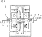
- FIG. 7 depicts a longitudinal section of the linear actuator according to FIG. 1 ;
- FIG. 8 depicts exemplary electrical circuitry of the linear actuator according to FIGS. 1 and 7 ;
- FIG. 9 depicts in a diagrammatic representation of an exemplary input signal for the activation of the linear actuator and exemplary coil signals according to the circuitry of the linear actuator according to FIG. 8 ;
- FIG. 10 depicts a perspective representation of the pump armature of the linear actuator according to FIG. 1 (A) and a diagrammatic representation of the pump armature according to FIG. 10 (A) in an arrangement together with a flow conducting device of the linear actuator of FIG. 1 ;
- FIG. 11 depicts an alternative embodiment of a linear actuator having a single-piece pump armature
- FIG. 12 depicts a further alternative embodiment of a linear actuator.
- the linear actuator represented in FIG. 1 includes a dual-chamber solenoid pump 10 having a two-way valve 20 , by which hydraulic fluid is pumped from a reservoir 30 into a working area of a hydraulic cylinder 40 .
- a hydraulic piston 50 is movably guided in a linear fashion in the hydraulic cylinder 40 .
- the pump direction of the dual-chamber solenoid pump 10 may be reversed, so that hydraulic fluid is pumped back into the reservoir 30 from the working area of the hydraulic cylinder 40 .
- the hydraulic piston 50 is moved forwards or backwards accordingly.
- the construction of the dual-chamber solenoid pump 10 is depicted in more detail in FIGS. 2A and 2B .
- the dual-chamber solenoid pump 10 includes two pump coils 60 and 70 .
- the two pump coils 60 and 70 are each configured in the form of a pot magnet.
- Present between the pump coils 60 and 70 is a magnetic pump armature 80 .
- the magnetic pump armature 80 is guided in a direction 90 perpendicular to pot base planes of the two pump coils 60 , 70 .
- the pump armature 80 includes two soft-magnetic perforated disks 100 , 110 that are connected to each other by a non-magnetic connecting pipe 120 .
- the non-magnetic connecting pipe 120 extends perpendicularly to the pot base planes of the two pump coils 60 , 70 .
- the perforated disks 100 , 110 are each suspended in a freely oscillating manner on diaphragms 130 , which in each case delimits and seals hydraulic chambers 140 , 150 .
- the hydraulic chambers 140 and 150 exhibit feed lines 160 , 170 that discharge respectively into the hydraulic chambers 140 , 150 to either side of the pump armature 80 via non-return valves 180 , 190 .
- the hydraulic chambers 140 , 150 exhibit outlet pipes 200 , 210 that lead away from the hydraulic chambers 140 , 150 via non-return valves 220 , 230 .
- the supply pipes 160 , 170 and the outlet pipes 200 , 210 are brought together respectively on the input side and on the output side to form a common inlet 240 and a common outlet 250 .
- the hydraulic chambers 140 , 150 are sealed by a non-magnetic pipe 260 , on which the pump armature 80 slides back and forth.
- the pump effect is achieved by the activation of the pump coil 60 , 70 represented in FIG. 3 (e.g., the current strength I of the energization of the left-hand pump coil 60 (curve EK) or the right-hand pump coil 70 (curve ZK) is shown in each case as a function of the time t). Either the left-hand pump coil 60 or the right-hand pump coil 70 is energized alternately.
- the pump armature 80 is drawn alternately to the left or to the right as a consequence of the magnetic reluctance principle (e.g., the desire to close the magnetic flow circuit appropriately).
- the arrows 270 , 280 illustrate the underlying magnetic flow through the pump coil yoke 290 , 300 in each case enclosing a pump coil 60 , 70 partially around a corresponding circumference.
- the pump coil yoke 290 , 300 in each case respectively encloses the pump coils 60 , 70 on respective sides facing away from the other pump coil 70 , 60 , in each case partially around the corresponding circumference.
- the hydraulic volume that is present between the pump coil 60 , 70 and the pump armature 80 is reduced and increased alternately by the movement of the pump armature 80 to the left or to the right.
- This hydraulic volume is filled with hydraulic fluid (e.g., silicon oil or glycerin in the represented illustrative embodiment).
- the pulsating changes in pressure consequently result in a unidirectional flow of the hydraulic oil from the inlet 240 to the outlet 250 .
- a two-way valve 20 in the form of a 4/2-way valve is provided, as illustrated in FIG. 1 .
- the two-way valve 20 is moved by a switching armature 310 and is therefore switched.
- the switching armature 310 is integrated into the dual-chamber solenoid pump 10 , as illustrated in FIG. 4 .
- a non-magnetic guide rod 320 is passed through the non-magnetic tube 260 at the center in the direction 90 perpendicularly to the pot base planes. This non-magnetic guide rod 320 is able to slide in the direction 90 perpendicularly to the pot base planes (e.g., horizontally in the representation according to FIG. 4 ).
- a switching armature 310 made of a soft-magnetic material is attached to the non-magnetic guide rod 320 .
- the pump coil yoke 290 and the pump coil yoke 300 are connected via a flow-conducting device 330 radially remotely from the non-magnetic connecting pipe 120 in the horizontal direction 90 .
- the flow-conducting device 330 exhibits protrusions 340 that extend radially in the direction of the non-magnetic connecting pipe 120 .
- a radially extending bar magnet 350 is attached in each case to the protrusion 340 .
- the switching armature 310 also exhibits corresponding protrusions 360 that extend along the switching armature 310 in the horizontal direction to such an extent that the protrusions 360 constantly overlap in the horizontal direction with the radially inward-facing protrusions 340 of the flow-conducting device 330 , when the switching armature 310 makes contact with the left-hand pump coil yoke 290 or the right-hand pump coil yoke 300 ( FIGS. 4A and 4B ). If the switching armature 310 is present in the left-hand position, as depicted in FIG.
- the magnetic flow of the bar magnet 350 is conducted mainly over the air gap (e.g., minimal air gap) and through the left-hand pump coil yoke 290 , because of the lower magnetic reluctance on this side.
- a holding force, which holds the switching armature 310 in this position, is produced there as a result.
- the switching armature is held in the right-hand position (e.g., the switching armature 310 is held in a position in each case both in the left-hand position of the switching armature 310 and in the right-hand position of the switching armature 310 ).
- a high current signal HSS is used for a short time, as depicted in FIG. 6 .
- the switching armature 310 is moved to the right by this short-time high current signal HSS.
- the right-hand pump coil 70 is subjected to a high current signal HSS for a short time.
- the temperature of the right-hand pump coil 70 increases for a short time (e.g., the pump coils 60 , 70 in each case are not actually designed for currents at a high level such as that reached in the case of the current signal HSS).
- the pump coils 60 , 70 may be configured for such high currents in further, not especially represented illustrative embodiments.
- the right-hand pump coil 70 is thus able to cool down during a short waiting period.
- the magnetic behavior during the switching operation is depicted in FIG. 5 .
- the presence of the high current actually causes the pump armature 80 to be drawn onto the side of the right-hand energized pump coil 70 , as is also the case in the pump sequence.
- the energization of the pump coil 70 is nevertheless so high that the magnetic circuit through the right-hand pump coil yoke 300 and the pump armature 80 (e.g., thin arrows 400 enclosing the right-hand pump coil 70 around the circumference of the righthand pump coil 70 ) rapidly becomes supersaturated.
- the magnetic flow will thus also flow via the flow-conducting device 330 of the bistable actuator.
- the magnetic flow F′ depicted with broken lines flows in the opposite direction to the flow of the bar magnet 350 on the holding side of the switching armature 310 .
- the flow of the pump coil 70 in the opposite direction is equally as high as the magnetic flow F of the bar magnet 350 .
- the holding force of the switching armature 310 is effectively increased.
- a magnetic flow 410 e.g., thick, drawn through
- the current may then be switched off, and the switching armature 310 remains stable at that point as a result of the flow path depicted in FIG. 4B .
- a switching operation is thus initiated by a briefly excessive energization (e.g., by a short-time current signal HSS having an excessive amplitude).
- the actuator as a whole is finally interconnected according to the principle drawing in FIG. 1 . Together with the envisaged two-way valve 20 , this is represented schematically in FIG. 7 , which corresponds to FIG. 1 .
- the circuit depicted in FIG. 8 is used to transmit the current signals, which act upon two pump coils (e.g., pump coil 60 and pump coil 70 ), as depicted in FIG. 3 and FIG. 6 , via a single pair of conductors.
- a signal source SQ supplies a single input signal ES with positive and negative signal components.
- the linear actuator includes two diodes D 1 , D 2 , by which the positive signal component EK is switched onto the pump coil 60 , and the negative signal component ZK is switched onto the pump coil 70 . This is depicted in FIG. 9 by way of example.
- the two-part pump actuator 80 includes two magnetic perforated disks 100 , 110 and a non-magnetic connecting pipe 120 .
- the connection of the two perforated disks 100 , 110 may also be effected with further, stabilizing connecting parts 500 that are arranged additionally to the non-magnetic connecting pipe 120 as supporting cylindrical elements between the perforated disks 100 , 110 .
- the protrusions 340 of the flow-conducting device 330 represented in FIG. 4 lie between the perforated disks 100 , 110 and may not be of a rotationally symmetrical embodiment, as represented in FIG. 10 (B), but may protrude radially onto the non-magnetic connecting pipe 120 from four directions offset from one another at a right angle.
- a two-part armature may be entirely avoided.
- the pump armature 80 ′ may be realized as a single perforated disk 100 ′. In this case, however, the pump armature 80 ′ is to be guided on the internal radius (e.g., by a further bellows). Magnetic flow is generated by a permanent magnet PM. In this case, the magnetic flow may only be led out “to the rear” from the pump coils 60 ′, 70 ′ in the direction of the bistable switching armature 310 ′. A magnetic constriction ENG is thus incorporated here.
- the linear actuator of one or more of the present embodiments is of thin and elongated configuration in a further embodiment (e.g., “pencil-like”).
- Longitudinal bellows LB are used in place of diaphragm bellows, as depicted in FIG. 12 , and the two-part pump armature 80 ′′ is provided with longitudinal bellows LB both on the internal radius and on the external radius.
- the guiding is realized by a number of non-magnetic guide rods FS.
- the design e.g., the magnetic design
- FIG. 4 the design
Landscapes
- Engineering & Computer Science (AREA)
- Mechanical Engineering (AREA)
- General Engineering & Computer Science (AREA)
- Physics & Mathematics (AREA)
- Fluid Mechanics (AREA)
- Electromagnetic Pumps, Or The Like (AREA)
- Reciprocating Pumps (AREA)
- Reciprocating, Oscillating Or Vibrating Motors (AREA)
- Magnetically Actuated Valves (AREA)
Abstract
Description
Claims (16)
Applications Claiming Priority (4)
| Application Number | Priority Date | Filing Date | Title |
|---|---|---|---|
| DE102014215110.4A DE102014215110A1 (en) | 2014-07-31 | 2014-07-31 | Linear actuator and method for operating such a linear actuator |
| DE102014215110 | 2014-07-31 | ||
| DE102014215110.4 | 2014-07-31 | ||
| PCT/EP2015/066534 WO2016016031A1 (en) | 2014-07-31 | 2015-07-20 | Linear actuator and method for operating such a linear actuator |
Publications (2)
| Publication Number | Publication Date |
|---|---|
| US20170218758A1 US20170218758A1 (en) | 2017-08-03 |
| US10731464B2 true US10731464B2 (en) | 2020-08-04 |
Family
ID=53794192
Family Applications (1)
| Application Number | Title | Priority Date | Filing Date |
|---|---|---|---|
| US15/500,833 Expired - Fee Related US10731464B2 (en) | 2014-07-31 | 2015-07-20 | Linear actuator and method for operating such a linear actuator |
Country Status (7)
| Country | Link |
|---|---|
| US (1) | US10731464B2 (en) |
| EP (1) | EP3146207A1 (en) |
| JP (1) | JP6452802B2 (en) |
| KR (1) | KR101996661B1 (en) |
| CN (1) | CN106662085B (en) |
| DE (1) | DE102014215110A1 (en) |
| WO (1) | WO2016016031A1 (en) |
Families Citing this family (1)
| Publication number | Priority date | Publication date | Assignee | Title |
|---|---|---|---|---|
| DE102020100240A1 (en) * | 2020-01-08 | 2021-07-08 | Bilfinger EMS GmbH | Pump and odorization system with such a pump |
Citations (19)
| Publication number | Priority date | Publication date | Assignee | Title |
|---|---|---|---|---|
| DE1088684B (en) | 1955-09-19 | 1960-09-08 | Ernst Thielenhaus Jun | Electro-hydraulic lifting device |
| US3018735A (en) | 1959-06-17 | 1962-01-30 | Mc Graw Edison Co | Electromagnetic vibratory pump |
| US3500079A (en) * | 1965-11-17 | 1970-03-10 | Maurice Barthalon | Electromagnetic machines |
| DE1703413A1 (en) | 1967-06-26 | 1972-01-13 | Jouvenel & Cordier | Vibration pump with electrovalve function |
| US3874822A (en) | 1973-10-31 | 1975-04-01 | Tadashi Nakamura | Electromagnetic plunger pump |
| DE2614004A1 (en) | 1975-04-16 | 1976-10-28 | Bridon Engineering Ltd | ACTUATION DEVICE |
| JPS5625366A (en) * | 1979-08-08 | 1981-03-11 | Matsushita Electric Ind Co Ltd | Electromagnetic reciprocating driving device |
| JPS5759981U (en) | 1980-09-26 | 1982-04-09 | ||
| DE3102032A1 (en) | 1981-01-22 | 1982-08-19 | Roland 7776 Owingen Dürig | Diaphragm pump |
| JPS5846861A (en) | 1981-08-20 | 1983-03-18 | ロ−ベルト・ボツシユ・ゲゼルシヤフト・ミツト・ベシユレンクテル・ハフツング | Electromagnetic drive device |
| US5013223A (en) | 1987-08-20 | 1991-05-07 | Takatsuki Electric Mfg. Co., Ltd. | Diaphragm-type air pump |
| JPH06185457A (en) * | 1991-11-27 | 1994-07-05 | Toshiyuki Nozawa | Pressure oil delivery device by magnetic force |
| JPH0727041A (en) | 1993-07-05 | 1995-01-27 | Kokusai Gijutsu Kaihatsu Kk | Reciprocating pump |
| US6264601B1 (en) * | 1999-04-02 | 2001-07-24 | World Heart Corporation | Implantable ventricular assist device |
| US6969345B2 (en) * | 2002-12-06 | 2005-11-29 | World Heart Corporation | Miniature, pulsatile implantable ventricular assist devices and methods of controlling ventricular assist devices |
| DE102004042208A1 (en) | 2004-09-01 | 2007-01-25 | Volkswagen Ag | Fluid e.g. hydraulic fluid, delivering piston pump for e.g. hydraulic braking system, has piston rod that is designed as drive rod and has ends, where one end is connected with linear motor and other end is connected with valve-control unit |
| DE102007014709A1 (en) | 2007-03-23 | 2008-09-25 | Carl Freudenberg Kg | Diaphragm pump for conveying a fluid |
| WO2014069435A1 (en) | 2012-11-05 | 2014-05-08 | カヤバ工業株式会社 | Cylinder control device |
| US20160294020A1 (en) | 2014-01-24 | 2016-10-06 | Johnson Controls Autobatterie Gmbh & Co. Kgaa | Mixing element, range of mixing elements, and accumulator |
Family Cites Families (1)
| Publication number | Priority date | Publication date | Assignee | Title |
|---|---|---|---|---|
| CN101294556A (en) | 2007-04-28 | 2008-10-29 | 德昌电机股份有限公司 | Solenoid pump |
-
2014
- 2014-07-31 DE DE102014215110.4A patent/DE102014215110A1/en not_active Withdrawn
-
2015
- 2015-07-20 US US15/500,833 patent/US10731464B2/en not_active Expired - Fee Related
- 2015-07-20 EP EP15747991.6A patent/EP3146207A1/en not_active Withdrawn
- 2015-07-20 JP JP2017505506A patent/JP6452802B2/en not_active Expired - Fee Related
- 2015-07-20 KR KR1020177002496A patent/KR101996661B1/en not_active Expired - Fee Related
- 2015-07-20 WO PCT/EP2015/066534 patent/WO2016016031A1/en not_active Ceased
- 2015-07-20 CN CN201580040771.6A patent/CN106662085B/en not_active Expired - Fee Related
Patent Citations (20)
| Publication number | Priority date | Publication date | Assignee | Title |
|---|---|---|---|---|
| DE1088684B (en) | 1955-09-19 | 1960-09-08 | Ernst Thielenhaus Jun | Electro-hydraulic lifting device |
| US3018735A (en) | 1959-06-17 | 1962-01-30 | Mc Graw Edison Co | Electromagnetic vibratory pump |
| US3500079A (en) * | 1965-11-17 | 1970-03-10 | Maurice Barthalon | Electromagnetic machines |
| DE1703413A1 (en) | 1967-06-26 | 1972-01-13 | Jouvenel & Cordier | Vibration pump with electrovalve function |
| US3874822A (en) | 1973-10-31 | 1975-04-01 | Tadashi Nakamura | Electromagnetic plunger pump |
| DE2614004A1 (en) | 1975-04-16 | 1976-10-28 | Bridon Engineering Ltd | ACTUATION DEVICE |
| JPS5625366A (en) * | 1979-08-08 | 1981-03-11 | Matsushita Electric Ind Co Ltd | Electromagnetic reciprocating driving device |
| JPS5759981U (en) | 1980-09-26 | 1982-04-09 | ||
| DE3102032A1 (en) | 1981-01-22 | 1982-08-19 | Roland 7776 Owingen Dürig | Diaphragm pump |
| JPS5846861A (en) | 1981-08-20 | 1983-03-18 | ロ−ベルト・ボツシユ・ゲゼルシヤフト・ミツト・ベシユレンクテル・ハフツング | Electromagnetic drive device |
| US5013223A (en) | 1987-08-20 | 1991-05-07 | Takatsuki Electric Mfg. Co., Ltd. | Diaphragm-type air pump |
| JPH06185457A (en) * | 1991-11-27 | 1994-07-05 | Toshiyuki Nozawa | Pressure oil delivery device by magnetic force |
| JPH0727041A (en) | 1993-07-05 | 1995-01-27 | Kokusai Gijutsu Kaihatsu Kk | Reciprocating pump |
| US6264601B1 (en) * | 1999-04-02 | 2001-07-24 | World Heart Corporation | Implantable ventricular assist device |
| US6969345B2 (en) * | 2002-12-06 | 2005-11-29 | World Heart Corporation | Miniature, pulsatile implantable ventricular assist devices and methods of controlling ventricular assist devices |
| DE102004042208A1 (en) | 2004-09-01 | 2007-01-25 | Volkswagen Ag | Fluid e.g. hydraulic fluid, delivering piston pump for e.g. hydraulic braking system, has piston rod that is designed as drive rod and has ends, where one end is connected with linear motor and other end is connected with valve-control unit |
| DE102007014709A1 (en) | 2007-03-23 | 2008-09-25 | Carl Freudenberg Kg | Diaphragm pump for conveying a fluid |
| WO2014069435A1 (en) | 2012-11-05 | 2014-05-08 | カヤバ工業株式会社 | Cylinder control device |
| US20160294020A1 (en) | 2014-01-24 | 2016-10-06 | Johnson Controls Autobatterie Gmbh & Co. Kgaa | Mixing element, range of mixing elements, and accumulator |
| JP2017505506A (en) | 2014-01-24 | 2017-02-16 | ジョンソン・コントロールズ・オートバッテリー・ゲーエムベーハー・ウント・コンパニー・カーゲーアーアーJohnson Controls Autobatterie Gmbh & Co. Kgaa | Mixing member, set of mixing members, and accumulator |
Non-Patent Citations (11)
| Title |
|---|
| Chinese Office Action for Chinese Application No. 201580040771.6 dated Nov. 7, 2018. |
| Directional Control Valve Symbols_Hydraulic Valve (Year: 2019). * |
| Directional Control Valves Symbols _ Hydraulic Valve, Feb. 2019. * |
| German Search Report for related German Application No. 10 2014 215 110.4 dated Oct. 29, 2015, with English Translation. |
| Japanese Grant Decision for Japanese Application No. 2017-505506, dated Nov. 12, 2018. |
| Japanese Office Action for Japanese Application No. 2017-505506, dated Feb. 19, 2018. |
| JP56025366 translation, Yokoo, Hitoshi (Year: 1981). * |
| JPH06185457 translation, JPH06185457, Jul. 1994, Nozawa Toshiyuki, F04B17/04. * |
| JPH06185457 translation, Nozawa Toshiyuki (Year: 1994). * |
| PCT International Search Report and Written Opinion of the International Searching Authority dated Nov. 6, 2015 or corresponding PCT/EP2015/066534, with English Translation. |
| Translation of DE102004042208A1, Feb. 2007, Damm; Ansgar, F04B17/04. * |
Also Published As
| Publication number | Publication date |
|---|---|
| JP2017530287A (en) | 2017-10-12 |
| JP6452802B2 (en) | 2019-01-16 |
| CN106662085A (en) | 2017-05-10 |
| WO2016016031A1 (en) | 2016-02-04 |
| EP3146207A1 (en) | 2017-03-29 |
| CN106662085B (en) | 2020-03-13 |
| KR20170024060A (en) | 2017-03-06 |
| DE102014215110A1 (en) | 2016-02-04 |
| KR101996661B1 (en) | 2019-07-04 |
| US20170218758A1 (en) | 2017-08-03 |
Similar Documents
| Publication | Publication Date | Title |
|---|---|---|
| EP0392784B1 (en) | Electromagnetic valve utilizing a permanent magnet | |
| JP5941471B2 (en) | Force equalization fixed coil actuator for fluid transfer device | |
| JP2014117149A (en) | Linear drive device and piston pump device | |
| CN105655088B (en) | Valve apparatus with electro-actuator-based valve and method for controlling the valve | |
| EP2621067A1 (en) | Linear actuator | |
| JP5462753B2 (en) | Electric / hydraulic linear servo valve | |
| US10731464B2 (en) | Linear actuator and method for operating such a linear actuator | |
| CN109496252B (en) | Oscillating squeeze pump with electric drive and method of operation | |
| CN107646075B (en) | Pump unit, braking system | |
| CN102305307B (en) | Linear servo device of hydraulic valve and operating method thereof | |
| US7201096B2 (en) | Linear motor having a magnetically biased neutral position | |
| CN103016824B (en) | A solenoid type single-drive multi-action electromagnet assembly | |
| JP2006158135A (en) | Linear actuator and valve device using it | |
| JP2007303645A (en) | Mr fluid valve | |
| JP2006329190A (en) | Magnetic force-driven pump unit | |
| JP2015119630A (en) | Linear drive | |
| JP5653285B2 (en) | Positive displacement pump | |
| JP2017060217A (en) | Actuator | |
| KR20210028002A (en) | EPM(Electro-Permanent Magnetic) drive metering pump | |
| JP5689671B2 (en) | Positive displacement pump drive control circuit and positive displacement pump | |
| RU2004120554A (en) | RETURNING AND ACCESSIBLE HYDRAULIC PUMP | |
| JP2006246550A (en) | Drive unit of electromagnetic capacity type pump | |
| JP5739720B2 (en) | Positive displacement pump drive control method and positive displacement pump | |
| JP5653286B2 (en) | Check valve | |
| WO2011136259A1 (en) | Method for controllably driving positive-displacement pump, and positive-displacement pump |
Legal Events
| Date | Code | Title | Description |
|---|---|---|---|
| AS | Assignment |
Owner name: SIEMENS AKTIENGESELLSCHAFT, GERMANY Free format text: ASSIGNMENT OF ASSIGNORS INTEREST;ASSIGNORS:BACHMAIER, GEORG;CYRIACKS, MARCO;FREITAG, REINHARD;AND OTHERS;SIGNING DATES FROM 20161220 TO 20161222;REEL/FRAME:041163/0285 |
|
| STPP | Information on status: patent application and granting procedure in general |
Free format text: NON FINAL ACTION MAILED |
|
| STPP | Information on status: patent application and granting procedure in general |
Free format text: RESPONSE TO NON-FINAL OFFICE ACTION ENTERED AND FORWARDED TO EXAMINER |
|
| STPP | Information on status: patent application and granting procedure in general |
Free format text: FINAL REJECTION MAILED |
|
| STPP | Information on status: patent application and granting procedure in general |
Free format text: ADVISORY ACTION MAILED |
|
| STPP | Information on status: patent application and granting procedure in general |
Free format text: RESPONSE AFTER FINAL ACTION FORWARDED TO EXAMINER |
|
| STPP | Information on status: patent application and granting procedure in general |
Free format text: DOCKETED NEW CASE - READY FOR EXAMINATION |
|
| STPP | Information on status: patent application and granting procedure in general |
Free format text: NON FINAL ACTION MAILED |
|
| STPP | Information on status: patent application and granting procedure in general |
Free format text: NOTICE OF ALLOWANCE MAILED -- APPLICATION RECEIVED IN OFFICE OF PUBLICATIONS |
|
| STPP | Information on status: patent application and granting procedure in general |
Free format text: PUBLICATIONS -- ISSUE FEE PAYMENT VERIFIED |
|
| STCF | Information on status: patent grant |
Free format text: PATENTED CASE |
|
| FEPP | Fee payment procedure |
Free format text: MAINTENANCE FEE REMINDER MAILED (ORIGINAL EVENT CODE: REM.); ENTITY STATUS OF PATENT OWNER: LARGE ENTITY |
|
| LAPS | Lapse for failure to pay maintenance fees |
Free format text: PATENT EXPIRED FOR FAILURE TO PAY MAINTENANCE FEES (ORIGINAL EVENT CODE: EXP.); ENTITY STATUS OF PATENT OWNER: LARGE ENTITY |
|
| STCH | Information on status: patent discontinuation |
Free format text: PATENT EXPIRED DUE TO NONPAYMENT OF MAINTENANCE FEES UNDER 37 CFR 1.362 |
|
| FP | Lapsed due to failure to pay maintenance fee |
Effective date: 20240804 |