US10725568B1 - Scroll module - Google Patents
Scroll module Download PDFInfo
- Publication number
- US10725568B1 US10725568B1 US16/548,978 US201916548978A US10725568B1 US 10725568 B1 US10725568 B1 US 10725568B1 US 201916548978 A US201916548978 A US 201916548978A US 10725568 B1 US10725568 B1 US 10725568B1
- Authority
- US
- United States
- Prior art keywords
- scroll
- rotating shaft
- groove
- module according
- module
- Prior art date
- Legal status (The legal status is an assumption and is not a legal conclusion. Google has not performed a legal analysis and makes no representation as to the accuracy of the status listed.)
- Active
Links
Images


Classifications
-
- G—PHYSICS
- G06—COMPUTING OR CALCULATING; COUNTING
- G06F—ELECTRIC DIGITAL DATA PROCESSING
- G06F3/00—Input arrangements for transferring data to be processed into a form capable of being handled by the computer; Output arrangements for transferring data from processing unit to output unit, e.g. interface arrangements
- G06F3/01—Input arrangements or combined input and output arrangements for interaction between user and computer
- G06F3/03—Arrangements for converting the position or the displacement of a member into a coded form
- G06F3/033—Pointing devices displaced or positioned by the user, e.g. mice, trackballs, pens or joysticks; Accessories therefor
- G06F3/0362—Pointing devices displaced or positioned by the user, e.g. mice, trackballs, pens or joysticks; Accessories therefor with detection of one-dimensional [1D] translations or rotations of an operating part of the device, e.g. scroll wheels, sliders, knobs, rollers or belts
-
- G—PHYSICS
- G06—COMPUTING OR CALCULATING; COUNTING
- G06F—ELECTRIC DIGITAL DATA PROCESSING
- G06F3/00—Input arrangements for transferring data to be processed into a form capable of being handled by the computer; Output arrangements for transferring data from processing unit to output unit, e.g. interface arrangements
- G06F3/01—Input arrangements or combined input and output arrangements for interaction between user and computer
- G06F3/03—Arrangements for converting the position or the displacement of a member into a coded form
- G06F3/0304—Detection arrangements using opto-electronic means
- G06F3/0312—Detection arrangements using opto-electronic means for tracking the rotation of a spherical or circular member, e.g. optical rotary encoders used in mice or trackballs using a tracking ball or in mouse scroll wheels
-
- G—PHYSICS
- G06—COMPUTING OR CALCULATING; COUNTING
- G06F—ELECTRIC DIGITAL DATA PROCESSING
- G06F3/00—Input arrangements for transferring data to be processed into a form capable of being handled by the computer; Output arrangements for transferring data from processing unit to output unit, e.g. interface arrangements
- G06F3/01—Input arrangements or combined input and output arrangements for interaction between user and computer
- G06F3/03—Arrangements for converting the position or the displacement of a member into a coded form
- G06F3/033—Pointing devices displaced or positioned by the user, e.g. mice, trackballs, pens or joysticks; Accessories therefor
- G06F3/0354—Pointing devices displaced or positioned by the user, e.g. mice, trackballs, pens or joysticks; Accessories therefor with detection of two-dimensional [2D] relative movements between the device, or an operating part thereof, and a plane or surface, e.g. 2D mice, trackballs, pens or pucks
- G06F3/03543—Mice or pucks
Definitions
- the present invention relates to a scroll module, and in particular to a scroll module applied to a mouse.
- a mouse is used to control a cursor on a computer screen so as to operate the computer.
- a scroll of the mouse is the most commonly used button for general users, for example, browsing a webpage or moving the cursor by rotating the scroll, or outputting middle button signals or switching between different functional modes by pressing the scroll.
- a mouse 9 includes: a housing 91 and a scroll 92 , where the housing 91 includes an upper cover 911 and a bottom 912 , and a control end of the upper cover 911 has a tilt design from upper right to bottom left, so that a user may rest fingers more comfortably.
- the scroll 92 usually has a lighting function. As shown in FIG. 2A and FIG.
- the scroll 92 has a groove 921 , and a rotating shaft 922 protrudes from a bottom surface of the groove;
- a luminous module 93 includes: a circuit board 931 and a luminous unit 932 , where the luminous unit 932 is arranged in the groove 921 , and is used to emit light to the scroll 92 , so that the scroll 92 produces a luminous visual effect.
- a middle button switch module 94 is disposed below the rotating shaft 922 .
- the luminous module 93 when the luminous module 93 is disposed above the rotating shaft 922 (as shown in FIG. 2A ), the luminous module 93 may be too close to the upper cover 911 , thereby affecting the tilt design of the upper cover 911 .
- the luminous module 93 When the scroll 92 is pressed, the luminous module 93 does not descend along with the scroll 92 , so that the luminous unit 932 is too close to or in contact with an inner circumference of the groove 921 , and therefore, the luminance produced by the scroll 92 changes, or light leakage even occurs.
- an extra rubber cap (not shown) needs to be disposed on the circuit board 931 near the luminous unit 932 to prevent damage to the luminous unit 932 caused by electrostatic discharge (ESD).
- the rotating shaft 922 may block the light emitted by the luminous unit 932 , resulting in lower luminance of the scroll 92 when the scroll shines.
- the technical problem to be solved in the present invention is to provide a scroll module, in which a relative arrangement of the rotating shaft and the luminous module does not affect the tilt design of the control end of the mouse, and the rotating shaft does not block the light emitted by the luminous module.
- a main objective of the present invention is to provide a scroll module, in which a relative arrangement of a rotating shaft and a luminous module does not affect a tilt design of a control end of a mouse, and the rotating shaft does not block light emitted by the luminous module, so that luminance of the scroll module can be maintained when the scroll module shines.
- the present invention provides a scroll module, applicable to a mouse, including:
- the scroll module further includes a luminous module, where the luminous module includes a circuit board and a luminous unit disposed on one end of the circuit board.
- the circuit board is partially arranged in the groove, the luminous unit is located below the first rotating shaft, the luminous unit is used to emit light, and the light may penetrate the first rotating shaft and be transmitted to the scroll.
- one end of the circuit board opposite to the luminous unit is fixed on a bottom of the mouse.
- the bottom surface of the groove further includes a positioning hole, and the positioning hole is located around the axle hole.
- the second surface has a positioning bump corresponding to the positioning hole, and the positioning bump passes through the positioning hole to fix the rotary disk.
- the rotating element is integrally formed, and is made of a transparent material.
- first rotating shaft and the second rotating shaft are integrally formed and pass through the central position of the rotary disk, and the first rotating shaft and the second rotating shaft are made of a transparent material.
- the first rotating shaft is made of a transparent material.
- an outer circumference of the scroll has an annular groove, and a rim is disposed in the annular groove.
- the scroll module further includes a round shading element, where the round shading element is used to cover another surface opposite to the groove, and has a central hole corresponding to the second rotating shaft.
- the scroll module further includes an annular shading element, where the annular shading element is disposed around the groove and used to partially cover the groove.
- the second rotating shaft has a polygonal shaft, where the polygonal shaft is used to connect an encoder of the mouse.
- FIG. 1 is a front view of a conventional mouse
- FIG. 2A and FIG. 2B are schematic three-dimensional view of a structure of a scroll of a conventional mouse
- FIG. 3 is a three-dimensional exploded view of a mouse according to the present invention.
- FIG. 4A is a three-dimensional exploded view of a scroll module from a visual angle according to the present invention.
- FIG. 4B is a three-dimensional exploded view of the scroll module from another visual angle according to the present invention.
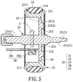
- FIG. 5 is a schematic diagram of the scroll module when the scroll module shines.
- FIG. 3 is a three-dimensional exploded view of a mouse according to the present invention.
- a mouse 1 includes: a housing 10 , a scroll module 20 , a luminous module 30 , a middle button switch module 40 , an encoder 50 , a main circuit board 60 and an electrical connector 70 .
- the housing 10 includes: an upper cover 101 and a bottom 102 , and the scroll module 20 , the luminous module 30 , the middle button switch module 40 , the encoder 50 and the main circuit board 60 are all disposed in an inner space formed by combination of the upper cover 101 and the bottom 102 .
- the main circuit board 60 is fixed on the bottom 102 , and the middle button switch module 40 and the encoder 50 are disposed on the main circuit board 60 .
- the bottom 102 has a first support element 1021 and a second support element 1022 which protrude upward from the bottom.
- the first support element 1021 is located on one side of the encoder 50 , and one end away from the bottom 102 of the first support element 1021 has a slide hole 10211 , where the slide hole 10211 corresponds to a polygonal axle hole 501 of the encoder 50 .
- the scroll module 20 is pivotally disposed in the slide hole 10211 , and may be connected to the encoder 50 through the polygonal axle hole 501 .
- a control end of the upper cover 101 has a through scroll hole 1011 , and the scroll module 20 may be partially exposed and protrude from the scroll hole 1011 .
- the second support element 1022 and the middle button switch module 40 are located on a same side.
- the luminous module 30 includes: a circuit board 301 and a luminous unit 302 disposed at an end of the circuit board 301 , one end of the circuit board 301 opposite to the luminous unit 302 may be fixed on the second support element 1022 in a locking manner, and one end of the circuit board 301 having the luminous unit 302 is arranged in the scroll module 20 .
- the luminous unit 302 may be: a light-emitting diode unit, an organic light-emitting diode unit, a quantum dot light-emitting diode unit or an electroluminance unit.
- the electrical connector 70 is electrically connected to the main circuit board 60 , and may be a universal serial bus interface, such as USB 2.0, USB 3.0 or USB 3.1, and is used to output button signals, middle button signals or scroll signals to an electronic device or a computer (not shown, such as a laptop or a personal computer) which is connected to the mouse 1 .
- This embodiment only proposes an implementation in which the electronic device or the computer is connected by using a wired electrical connector 70 , but in practical applications, the electrical connector 70 may also be replaced by an existing wireless connection module. This shall not be limited by the implementation proposed in this embodiment.
- the scroll module 20 may drive the encoder 50 at the same time, so that the encoder 50 may sense a rotation distance, a rotation direction and a rotation speed of the scroll module 20 , and output a corresponding scroll signal; and when a user presses the scroll module 20 , the scroll module 20 may move downward along the slide hole 10211 , and press the middle button switch module 40 to output a corresponding middle button signal.
- FIG. 4A is a three-dimensional exploded view of a scroll module from a visual angle according to the present invention
- FIG. 4B is a three-dimensional exploded view of the scroll module from another visual angle according to the present invention.
- the scroll module 20 includes: a scroll 21 , a rim 22 , a rotating element 23 , a round shading element 24 and an annular shading element 25 .
- the scroll 21 includes: a groove 211 and an annular groove 214 .
- a bottom surface of the groove 211 has a through axle hole 212 and one or more positioning holes 213 around the axle hole 212 .
- the annular groove 214 is disposed on an outer circumference of the scroll 21 , and the rim 22 may be disposed in the annular groove.
- the rim 22 may be made of a light-proof elastic material to increase a friction force on the surface of the scroll 21 , and to provide a good pressing feel.
- the rotating element 23 includes: a rotary disk 231 , a first rotating shaft 23111 , a second rotating shaft 23121 and one or more positioning bumps 23122 .
- the rotary disk 231 has a first surface 2311 and a second surface 2312 opposite to each other, the first rotating shaft 23111 is disposed at a central position of the first surface 2311 , the second rotating shaft 23121 is disposed at a central position on the second surface 2312 , and the positioning bump 23122 is disposed on the second surface 2312 and around the second rotating shaft 23121 .
- a position, a shape or a quantity of the positioning bump 23122 corresponds to a position, a shape or a quantity of the positioning hole 213 on the bottom surface of the groove 211 .
- the rotating element 23 When the rotating element 23 is installed in the groove 211 , the second surface 2312 of the rotary disk 231 faces the bottom surface of the groove 211 , the second rotating shaft 23121 and the positioning bump 23122 pass through the axle hole 212 and the positioning hole 213 respectively, and the rotary disk 231 may be fixed on the bottom surface of the groove 211 by using combination of the positioning bump 23122 and the positioning hole 213 .
- This embodiment only proposes an implementation in which the rotating element 23 and the scroll 21 are assembled by using the combination of the positioning bump 23122 and the positioning hole 213 , but in practical applications, the positioning bump 23122 may be disposed on the bottom surface of the groove 211 , and the positioning hole 213 may be disposed on the rotary disk 231 .
- the rotary disk 231 may be fixed on the bottom surface of the groove 211 by the means of glueing or clamping.
- the second rotating shaft 23121 has a polygonal shaft 231211 corresponding to the polygonal axle hole 501 (as shown in FIG. 3 ) of the encoder 50 .
- the second rotating shaft 23121 passes in sequence through the slide hole 10211 of the support element 1021 and the polygonal axle hole 501 of the encoder 50 , and the polygonal shaft 231211 passes through and is fixed in the polygonal axle hole 501 . Therefore, when the scroll module 20 rotates, the rotating element 23 may drive the encoder 50 to rotate.
- the rotating element 23 is integrally formed, and is made of a transparent material, so that the light can penetrate the rotating element 23 .
- the first rotating shaft 23111 and the second rotating shaft 23121 are integrally formed, and pass through a central position of a rotary disk 231 , and the first rotating shaft 23111 and the second rotating shaft 23121 are made of a transparent material.
- the rotary disk 231 is made of a light-proof material.
- the first rotating shaft 23111 is made of a transparent material, and is fixed at a central position on the first surface 2311 of the rotary disk 231 ; and the rotary disk 231 is made of a light-proof material.
- the round shading element 24 is used to cover another surface opposite to the groove 211 , and has a central hole 241 corresponding to the second rotating shaft 23121 .
- the annular shading element 25 is disposed around the groove 211 , and partially covers an edge of the groove 211 .
- FIG. 5 is a schematic diagram of the scroll module when the scroll module shines.
- One end of the circuit board 301 is partially arranged in the groove 211 , and the luminous unit 302 of the luminous module 30 is located below the first rotating shaft 23111 .
- the luminous unit 302 is used to emit light L, and the light L may penetrate the first rotating shaft 23111 and be transmitted to the scroll 21 .
- the round shading element 24 and the annular shading element 25 are used to cover two opposite sides of the scroll 21 , so as to prevent or reduce the dissipation of the light L from the two opposite sides of the scroll 21 .
- the light L may come out from an area which is not covered by the round shading element 24 , the annular shading element 25 and the rim 22 , so that the scroll module 20 may produce a luminous visual effect.
- a light diffusion agent or titanium dioxide may be added when the scroll 21 is produced to improve the luminance and uniformity when the scroll 21 shines.
- the rim 22 may be made of a light-transmissive elastic material. After the light L is transmitted to the scroll 21 , the light may penetrate from a position where the rim 22 is disposed, so that the luminous scope of the scroll 21 is increased.
- the rotating shaft of the scroll module provided in the present invention has light penetrability.
- the luminous module When the luminous module is disposed below the rotating shaft, the light produced by the luminous module may penetrate the rotating shaft which has the light penetrability, and be transmitted to the scroll, so that the luminance and the uniformity when the scroll module shines may be maintained.
- the luminous module is disposed below the rotating shaft, so that the tilt design of the control end of the mouse is not affected.
- the luminous unit of the luminous module may be far away from the inner circumference of the scroll groove, so that the damage of the luminous unit caused by the electrostatic discharge may be effectively avoided. Therefore, the present invention is actually a creation with great industrial value.
Landscapes
- Engineering & Computer Science (AREA)
- General Engineering & Computer Science (AREA)
- Theoretical Computer Science (AREA)
- Human Computer Interaction (AREA)
- Physics & Mathematics (AREA)
- General Physics & Mathematics (AREA)
- Position Input By Displaying (AREA)
Abstract
The present invention provides a scroll module applicable to a mouse, including: a scroll and a rotating element. The rotating element is installed in a groove of the scroll, and a first rotating shaft of the rotating element has light penetrability.
Description
The present invention relates to a scroll module, and in particular to a scroll module applied to a mouse.
A mouse is used to control a cursor on a computer screen so as to operate the computer. In addition to a left button and a right button, a scroll of the mouse is the most commonly used button for general users, for example, browsing a webpage or moving the cursor by rotating the scroll, or outputting middle button signals or switching between different functional modes by pressing the scroll.
To make users feel more comfortable when using the mouse, many ergonomic designs have also been widely applied in mouse housings. As shown in FIG. 1 , a mouse 9 includes: a housing 91 and a scroll 92, where the housing 91 includes an upper cover 911 and a bottom 912, and a control end of the upper cover 911 has a tilt design from upper right to bottom left, so that a user may rest fingers more comfortably. In addition, to improve the convenience of mouse operation in a dark environment and attract more attention from consumers, the scroll 92 usually has a lighting function. As shown in FIG. 2A and FIG. 2B , the scroll 92 has a groove 921, and a rotating shaft 922 protrudes from a bottom surface of the groove; a luminous module 93 includes: a circuit board 931 and a luminous unit 932, where the luminous unit 932 is arranged in the groove 921, and is used to emit light to the scroll 92, so that the scroll 92 produces a luminous visual effect. A middle button switch module 94 is disposed below the rotating shaft 922.
In the prior art, when the luminous module 93 is disposed above the rotating shaft 922 (as shown in FIG. 2A ), the luminous module 93 may be too close to the upper cover 911, thereby affecting the tilt design of the upper cover 911. When the scroll 92 is pressed, the luminous module 93 does not descend along with the scroll 92, so that the luminous unit 932 is too close to or in contact with an inner circumference of the groove 921, and therefore, the luminance produced by the scroll 92 changes, or light leakage even occurs. If the luminous unit 932 is too close to or in contact with the inner circumference of the groove 921, an extra rubber cap (not shown) needs to be disposed on the circuit board 931 near the luminous unit 932 to prevent damage to the luminous unit 932 caused by electrostatic discharge (ESD).
However, when the luminous module 93 is disposed below the rotating shaft 922 (as shown in FIG. 2B ), the rotating shaft 922 may block the light emitted by the luminous unit 932, resulting in lower luminance of the scroll 92 when the scroll shines.
Therefore, the technical problem to be solved in the present invention is to provide a scroll module, in which a relative arrangement of the rotating shaft and the luminous module does not affect the tilt design of the control end of the mouse, and the rotating shaft does not block the light emitted by the luminous module.
A main objective of the present invention is to provide a scroll module, in which a relative arrangement of a rotating shaft and a luminous module does not affect a tilt design of a control end of a mouse, and the rotating shaft does not block light emitted by the luminous module, so that luminance of the scroll module can be maintained when the scroll module shines.
To achieve the above objective, the present invention provides a scroll module, applicable to a mouse, including:
-
- a scroll, having a groove, where a bottom surface of the groove has a through axle hole; and
- a rotating element, installed in the groove, including:
- a rotary disk, having a first surface and a second surface opposite to each other;
- a first rotating shaft, disposed at a central position of the first surface; and
- a second rotating shaft, disposed at a central position of the second surface;
- where the rotary disk is fixed on the bottom surface of the groove and the second rotating shaft passes through the axle hole, and the first rotating shaft has light penetrability.
In the above preferred embodiment, the scroll module further includes a luminous module, where the luminous module includes a circuit board and a luminous unit disposed on one end of the circuit board.
In the above preferred embodiment, the circuit board is partially arranged in the groove, the luminous unit is located below the first rotating shaft, the luminous unit is used to emit light, and the light may penetrate the first rotating shaft and be transmitted to the scroll.
In the above preferred embodiment, one end of the circuit board opposite to the luminous unit is fixed on a bottom of the mouse.
In the above preferred embodiment, the bottom surface of the groove further includes a positioning hole, and the positioning hole is located around the axle hole.
In the above preferred embodiment, the second surface has a positioning bump corresponding to the positioning hole, and the positioning bump passes through the positioning hole to fix the rotary disk.
In the above preferred embodiment, the rotating element is integrally formed, and is made of a transparent material.
In the above preferred embodiment, the first rotating shaft and the second rotating shaft are integrally formed and pass through the central position of the rotary disk, and the first rotating shaft and the second rotating shaft are made of a transparent material.
In the above preferred embodiment, the first rotating shaft is made of a transparent material.
In the above preferred embodiment, an outer circumference of the scroll has an annular groove, and a rim is disposed in the annular groove.
In the above preferred embodiment, the scroll module further includes a round shading element, where the round shading element is used to cover another surface opposite to the groove, and has a central hole corresponding to the second rotating shaft.
In the above preferred embodiment, the scroll module further includes an annular shading element, where the annular shading element is disposed around the groove and used to partially cover the groove.
In the above preferred embodiment, the second rotating shaft has a polygonal shaft, where the polygonal shaft is used to connect an encoder of the mouse.
Advantages and features of the present invention and methods of achieving them will become easier to understand with reference to detailed description of exemplary embodiments and accompanying drawings. However, the present invention may be implemented in different forms and shall not be understood as being limited only to the embodiments described herein. On the contrary, for persons of ordinary skill in the art, the embodiments provided herein make the disclosure convey the scope of the present invention in a more thorough, comprehensive and complete manner.
First, FIG. 3 is a three-dimensional exploded view of a mouse according to the present invention. In FIG. 1 , a mouse 1 includes: a housing 10, a scroll module 20, a luminous module 30, a middle button switch module 40, an encoder 50, a main circuit board 60 and an electrical connector 70.
The housing 10 includes: an upper cover 101 and a bottom 102, and the scroll module 20, the luminous module 30, the middle button switch module 40, the encoder 50 and the main circuit board 60 are all disposed in an inner space formed by combination of the upper cover 101 and the bottom 102. The main circuit board 60 is fixed on the bottom 102, and the middle button switch module 40 and the encoder 50 are disposed on the main circuit board 60.
The bottom 102 has a first support element 1021 and a second support element 1022 which protrude upward from the bottom. The first support element 1021 is located on one side of the encoder 50, and one end away from the bottom 102 of the first support element 1021 has a slide hole 10211, where the slide hole 10211 corresponds to a polygonal axle hole 501 of the encoder 50. The scroll module 20 is pivotally disposed in the slide hole 10211, and may be connected to the encoder 50 through the polygonal axle hole 501. A control end of the upper cover 101 has a through scroll hole 1011, and the scroll module 20 may be partially exposed and protrude from the scroll hole 1011. In addition, the second support element 1022 and the middle button switch module 40 are located on a same side. In this embodiment, the luminous module 30 includes: a circuit board 301 and a luminous unit 302 disposed at an end of the circuit board 301, one end of the circuit board 301 opposite to the luminous unit 302 may be fixed on the second support element 1022 in a locking manner, and one end of the circuit board 301 having the luminous unit 302 is arranged in the scroll module 20. The luminous unit 302 may be: a light-emitting diode unit, an organic light-emitting diode unit, a quantum dot light-emitting diode unit or an electroluminance unit.
The electrical connector 70 is electrically connected to the main circuit board 60, and may be a universal serial bus interface, such as USB 2.0, USB 3.0 or USB 3.1, and is used to output button signals, middle button signals or scroll signals to an electronic device or a computer (not shown, such as a laptop or a personal computer) which is connected to the mouse 1. This embodiment only proposes an implementation in which the electronic device or the computer is connected by using a wired electrical connector 70, but in practical applications, the electrical connector 70 may also be replaced by an existing wireless connection module. This shall not be limited by the implementation proposed in this embodiment.
When a user rolls the scroll module 20, the scroll module 20 may drive the encoder 50 at the same time, so that the encoder 50 may sense a rotation distance, a rotation direction and a rotation speed of the scroll module 20, and output a corresponding scroll signal; and when a user presses the scroll module 20, the scroll module 20 may move downward along the slide hole 10211, and press the middle button switch module 40 to output a corresponding middle button signal.
With reference to FIG. 4A and FIG. 4B , FIG. 4A is a three-dimensional exploded view of a scroll module from a visual angle according to the present invention, and FIG. 4B is a three-dimensional exploded view of the scroll module from another visual angle according to the present invention. The scroll module 20 includes: a scroll 21, a rim 22, a rotating element 23, a round shading element 24 and an annular shading element 25.
The scroll 21 includes: a groove 211 and an annular groove 214. A bottom surface of the groove 211 has a through axle hole 212 and one or more positioning holes 213 around the axle hole 212. The annular groove 214 is disposed on an outer circumference of the scroll 21, and the rim 22 may be disposed in the annular groove. In this embodiment, the rim 22 may be made of a light-proof elastic material to increase a friction force on the surface of the scroll 21, and to provide a good pressing feel.
The rotating element 23 includes: a rotary disk 231, a first rotating shaft 23111, a second rotating shaft 23121 and one or more positioning bumps 23122. The rotary disk 231 has a first surface 2311 and a second surface 2312 opposite to each other, the first rotating shaft 23111 is disposed at a central position of the first surface 2311, the second rotating shaft 23121 is disposed at a central position on the second surface 2312, and the positioning bump 23122 is disposed on the second surface 2312 and around the second rotating shaft 23121. A position, a shape or a quantity of the positioning bump 23122 corresponds to a position, a shape or a quantity of the positioning hole 213 on the bottom surface of the groove 211. When the rotating element 23 is installed in the groove 211, the second surface 2312 of the rotary disk 231 faces the bottom surface of the groove 211, the second rotating shaft 23121 and the positioning bump 23122 pass through the axle hole 212 and the positioning hole 213 respectively, and the rotary disk 231 may be fixed on the bottom surface of the groove 211 by using combination of the positioning bump 23122 and the positioning hole 213. This embodiment only proposes an implementation in which the rotating element 23 and the scroll 21 are assembled by using the combination of the positioning bump 23122 and the positioning hole 213, but in practical applications, the positioning bump 23122 may be disposed on the bottom surface of the groove 211, and the positioning hole 213 may be disposed on the rotary disk 231. Alternatively, it is not needed to dispose the positioning hole 213 on the bottom surface of the groove 211, and to dispose a corresponding positioning bump 23122 on the second surface 2312 of the rotary disk 231. Instead, the rotary disk 231 may be fixed on the bottom surface of the groove 211 by the means of glueing or clamping.
The second rotating shaft 23121 has a polygonal shaft 231211 corresponding to the polygonal axle hole 501 (as shown in FIG. 3 ) of the encoder 50. When the scroll 21 is installed, the second rotating shaft 23121 passes in sequence through the slide hole 10211 of the support element 1021 and the polygonal axle hole 501 of the encoder 50, and the polygonal shaft 231211 passes through and is fixed in the polygonal axle hole 501. Therefore, when the scroll module 20 rotates, the rotating element 23 may drive the encoder 50 to rotate.
Referring again to FIG. 4A and FIG. 4B , the rotating element 23 is integrally formed, and is made of a transparent material, so that the light can penetrate the rotating element 23. In another possible implementation, the first rotating shaft 23111 and the second rotating shaft 23121 are integrally formed, and pass through a central position of a rotary disk 231, and the first rotating shaft 23111 and the second rotating shaft 23121 are made of a transparent material. The rotary disk 231 is made of a light-proof material. In another possible implementation, the first rotating shaft 23111 is made of a transparent material, and is fixed at a central position on the first surface 2311 of the rotary disk 231; and the rotary disk 231 is made of a light-proof material.
The round shading element 24 is used to cover another surface opposite to the groove 211, and has a central hole 241 corresponding to the second rotating shaft 23121. The annular shading element 25 is disposed around the groove 211, and partially covers an edge of the groove 211.
Compared with a mouse scroll structure in conventional technologies, the rotating shaft of the scroll module provided in the present invention has light penetrability. When the luminous module is disposed below the rotating shaft, the light produced by the luminous module may penetrate the rotating shaft which has the light penetrability, and be transmitted to the scroll, so that the luminance and the uniformity when the scroll module shines may be maintained. The luminous module is disposed below the rotating shaft, so that the tilt design of the control end of the mouse is not affected. In addition, the luminous unit of the luminous module may be far away from the inner circumference of the scroll groove, so that the damage of the luminous unit caused by the electrostatic discharge may be effectively avoided. Therefore, the present invention is actually a creation with great industrial value.
Persons of ordinary skill in the art may make variations and modifications to the present invention without departing from the protection scope defined by the appended claims.
Claims (13)
1. A scroll module, applicable to a mouse, comprising:
a scroll, having a groove, wherein a bottom surface of the groove has a through axle hole; and
a rotating element, installed in the groove, comprising:
a rotary disk, having a first surface and a second surface opposite to each other;
a first rotating shaft, disposed at a central position of the first surface;
a second rotating shaft, disposed at a central position of the second surface; and
at least one luminous unit that emits light;
wherein the rotary disk is fixed on the bottom surface of the groove and the second rotating shaft passes through the axle hole, and the light penetrates the first rotating shaft to transmit the light to the scroll.
2. The scroll module according to claim 1 , further comprising a luminous module, wherein the luminous module comprises a circuit board and the at least one luminous unit disposed on one end of the circuit board.
3. The scroll module according to claim 2 , wherein the circuit board is partially arranged in the groove, the at least one luminous unit is located below the first rotating shaft.
4. The scroll module according to claim 2 , wherein one end of the circuit board opposite to the at least one luminous unit is fixed on a bottom of the mouse.
5. The scroll module according to claim 1 , wherein the bottom surface of the groove further comprises at least one positioning hole, and the at least one positioning hole is located around the axle hole.
6. The scroll module according to claim 5 , wherein the second surface has at least one positioning bump corresponding to the at least one positioning hole, and the at least one positioning bump passes through the at least one positioning hole to fix the rotary disk.
7. The scroll module according to claim 1 , wherein the rotating element is integrally formed, and is made of a transparent material.
8. The scroll module according to claim 1 , wherein the first rotating shaft and the second rotating shaft are integrally formed and pass through the central position of the rotary disk, and the first rotating shaft and the second rotating shaft are made of a transparent material.
9. The scroll module according to claim 1 , wherein the first rotating shaft is made of a transparent material.
10. The scroll module according to claim 1 , wherein an outer circumference of the scroll has an annular groove, and a rim is disposed in the annular groove.
11. The scroll module according to claim 1 , further comprising a round shading element, wherein the round shading element is used to cover another surface opposite to the groove, and has a central hole corresponding to the second rotating shaft.
12. The scroll module according to claim 1 , further comprising an annular shading element, wherein the annular shading element is disposed around the groove and is used to partially cover the groove.
13. The scroll module according to claim 1 , wherein the second rotating shaft has a polygonal shaft, and the polygonal shaft is used to connect an encoder of the mouse.
Applications Claiming Priority (2)
| Application Number | Priority Date | Filing Date | Title |
|---|---|---|---|
| TW108122934A | 2019-06-28 | ||
| TW108122934A TWI696063B (en) | 2019-06-28 | 2019-06-28 | Scroll module |
Publications (1)
| Publication Number | Publication Date |
|---|---|
| US10725568B1 true US10725568B1 (en) | 2020-07-28 |
Family
ID=71783214
Family Applications (1)
| Application Number | Title | Priority Date | Filing Date |
|---|---|---|---|
| US16/548,978 Active US10725568B1 (en) | 2019-06-28 | 2019-08-23 | Scroll module |
Country Status (2)
| Country | Link |
|---|---|
| US (1) | US10725568B1 (en) |
| TW (1) | TWI696063B (en) |
Cited By (3)
| Publication number | Priority date | Publication date | Assignee | Title |
|---|---|---|---|---|
| US11175702B2 (en) * | 2019-11-15 | 2021-11-16 | Primax Electronics Ltd. | Scroll mouse |
| US11422640B2 (en) * | 2020-11-06 | 2022-08-23 | Chicony Electronics Co., Ltd. | Mouse structure |
| US12345402B1 (en) * | 2024-03-29 | 2025-07-01 | Logitech Europe S.A. | Scroll wheel with lighting |
Families Citing this family (3)
| Publication number | Priority date | Publication date | Assignee | Title |
|---|---|---|---|---|
| TWI750770B (en) | 2020-08-12 | 2021-12-21 | 群光電子股份有限公司 | Roller input device |
| TWI817843B (en) * | 2022-01-27 | 2023-10-01 | 達方電子股份有限公司 | Wheel device and mouse |
| CN116627266A (en) * | 2022-02-14 | 2023-08-22 | 致伸科技股份有限公司 | Luminous roller structure |
Citations (13)
| Publication number | Priority date | Publication date | Assignee | Title |
|---|---|---|---|---|
| US20030025673A1 (en) * | 2001-04-30 | 2003-02-06 | Microsoft Corporation | Input device including a wheel assembly for scrolling an image in multiple directions |
| US20070109152A1 (en) * | 2005-11-14 | 2007-05-17 | Wald Steven F | Method and apparatus for optically detecting selections made on an input device |
| US20070222752A1 (en) * | 2006-03-27 | 2007-09-27 | Wen-Pin Hsieh | Computer mouse |
| US20090122012A1 (en) * | 2007-11-13 | 2009-05-14 | Microsoft Corporation | User input device with ring-shaped scroll wheel |
| US7616188B1 (en) * | 2003-08-22 | 2009-11-10 | Logitech Europe S.A. | Mouse roller with horizontal scrolling and horizontal tilting switch |
| US20100265180A1 (en) * | 2009-04-20 | 2010-10-21 | Pixart Imaging Inc. | Mouse wheel assembly |
| US20110025311A1 (en) * | 2009-07-29 | 2011-02-03 | Logitech Europe S.A. | Magnetic rotary system for input devices |
| US20140015752A1 (en) * | 2012-07-13 | 2014-01-16 | Primax Electronics Ltd. | Power-saving method for wheel mouse |
| US20140333536A1 (en) * | 2013-05-10 | 2014-11-13 | Microsoft Corporation | Scroll wheel with detent |
| US20150112457A1 (en) * | 2013-10-17 | 2015-04-23 | Heng Yu Technology (Hong Kong) Limited | Electronic Device and Control Method thereof |
| US20180364817A1 (en) * | 2015-12-14 | 2018-12-20 | Denso Corporation | Operating device |
| US20190094994A1 (en) * | 2017-09-28 | 2019-03-28 | Primax Electronics Ltd. | Mouse with inertia scroll wheel module |
| US20190272048A1 (en) * | 2018-03-01 | 2019-09-05 | Primax Electronics Ltd | Mouse device |
Family Cites Families (4)
| Publication number | Priority date | Publication date | Assignee | Title |
|---|---|---|---|---|
| US8330719B2 (en) * | 2009-11-24 | 2012-12-11 | Cheng Uei Precision Industry Co., Ltd. | Mouse |
| TWI432998B (en) * | 2010-01-29 | 2014-04-01 | Primax Electronics Ltd | Input device with illuminated roller |
| CN202661961U (en) * | 2012-01-04 | 2013-01-09 | 深圳市索艾电子科技有限公司 | Mouse |
| US9874948B2 (en) * | 2016-04-15 | 2018-01-23 | Dexin Corporation | Mouse device with movable signal input module |
-
2019
- 2019-06-28 TW TW108122934A patent/TWI696063B/en active
- 2019-08-23 US US16/548,978 patent/US10725568B1/en active Active
Patent Citations (13)
| Publication number | Priority date | Publication date | Assignee | Title |
|---|---|---|---|---|
| US20030025673A1 (en) * | 2001-04-30 | 2003-02-06 | Microsoft Corporation | Input device including a wheel assembly for scrolling an image in multiple directions |
| US7616188B1 (en) * | 2003-08-22 | 2009-11-10 | Logitech Europe S.A. | Mouse roller with horizontal scrolling and horizontal tilting switch |
| US20070109152A1 (en) * | 2005-11-14 | 2007-05-17 | Wald Steven F | Method and apparatus for optically detecting selections made on an input device |
| US20070222752A1 (en) * | 2006-03-27 | 2007-09-27 | Wen-Pin Hsieh | Computer mouse |
| US20090122012A1 (en) * | 2007-11-13 | 2009-05-14 | Microsoft Corporation | User input device with ring-shaped scroll wheel |
| US20100265180A1 (en) * | 2009-04-20 | 2010-10-21 | Pixart Imaging Inc. | Mouse wheel assembly |
| US20110025311A1 (en) * | 2009-07-29 | 2011-02-03 | Logitech Europe S.A. | Magnetic rotary system for input devices |
| US20140015752A1 (en) * | 2012-07-13 | 2014-01-16 | Primax Electronics Ltd. | Power-saving method for wheel mouse |
| US20140333536A1 (en) * | 2013-05-10 | 2014-11-13 | Microsoft Corporation | Scroll wheel with detent |
| US20150112457A1 (en) * | 2013-10-17 | 2015-04-23 | Heng Yu Technology (Hong Kong) Limited | Electronic Device and Control Method thereof |
| US20180364817A1 (en) * | 2015-12-14 | 2018-12-20 | Denso Corporation | Operating device |
| US20190094994A1 (en) * | 2017-09-28 | 2019-03-28 | Primax Electronics Ltd. | Mouse with inertia scroll wheel module |
| US20190272048A1 (en) * | 2018-03-01 | 2019-09-05 | Primax Electronics Ltd | Mouse device |
Cited By (3)
| Publication number | Priority date | Publication date | Assignee | Title |
|---|---|---|---|---|
| US11175702B2 (en) * | 2019-11-15 | 2021-11-16 | Primax Electronics Ltd. | Scroll mouse |
| US11422640B2 (en) * | 2020-11-06 | 2022-08-23 | Chicony Electronics Co., Ltd. | Mouse structure |
| US12345402B1 (en) * | 2024-03-29 | 2025-07-01 | Logitech Europe S.A. | Scroll wheel with lighting |
Also Published As
| Publication number | Publication date |
|---|---|
| TWI696063B (en) | 2020-06-11 |
| TW202101157A (en) | 2021-01-01 |
Similar Documents
| Publication | Publication Date | Title |
|---|---|---|
| US10725568B1 (en) | Scroll module | |
| TWI432998B (en) | Input device with illuminated roller | |
| CN107210158B (en) | Input device and electronic equipment using the same | |
| US9063597B2 (en) | Stylus and touch input system | |
| US8743056B2 (en) | Waterproof computer mouse | |
| CN204178989U (en) | Light-emitting structure around the keyboard backlight module | |
| TWM448778U (en) | Protective cover and keyboard | |
| US10775908B1 (en) | Luminous scroll module | |
| CN101315840B (en) | Movable contact element and switch using the same | |
| US11614810B2 (en) | Input device | |
| US12198876B2 (en) | Key structure | |
| CN112148140B (en) | Roller module | |
| CN102193654B (en) | Input device with light emitting roller module | |
| US8231236B2 (en) | Input apparatus and light guiding plate thereof | |
| CN202521384U (en) | Backlight module and luminous keyboard with same | |
| CN112181169B (en) | Luminous roller module | |
| US11914794B2 (en) | Keyboard with surface lighting apparatus | |
| TWM537254U (en) | Keyswitch device and circuit board assembly | |
| TWI796150B (en) | Luminous roller structure | |
| TWM535343U (en) | Keyswitch device and keyboard | |
| US20080129690A1 (en) | Pointing stick structure for input device | |
| US11810739B2 (en) | Electronic device and knob module thereof | |
| CN105281740A (en) | Key device and terminal | |
| CN114974973B (en) | button | |
| TWM509970U (en) | Illuminated keyboard device |
Legal Events
| Date | Code | Title | Description |
|---|---|---|---|
| FEPP | Fee payment procedure |
Free format text: ENTITY STATUS SET TO UNDISCOUNTED (ORIGINAL EVENT CODE: BIG.); ENTITY STATUS OF PATENT OWNER: LARGE ENTITY |
|
| STCF | Information on status: patent grant |
Free format text: PATENTED CASE |
|
| MAFP | Maintenance fee payment |
Free format text: PAYMENT OF MAINTENANCE FEE, 4TH YEAR, LARGE ENTITY (ORIGINAL EVENT CODE: M1551); ENTITY STATUS OF PATENT OWNER: LARGE ENTITY Year of fee payment: 4 |