US10721578B2 - Spatial audio warp compensator - Google Patents
Spatial audio warp compensator Download PDFInfo
- Publication number
- US10721578B2 US10721578B2 US15/606,375 US201715606375A US10721578B2 US 10721578 B2 US10721578 B2 US 10721578B2 US 201715606375 A US201715606375 A US 201715606375A US 10721578 B2 US10721578 B2 US 10721578B2
- Authority
- US
- United States
- Prior art keywords
- spatial
- geometric model
- location
- face
- geometry
- Prior art date
- Legal status (The legal status is an assumption and is not a legal conclusion. Google has not performed a legal analysis and makes no representation as to the accuracy of the status listed.)
- Active, expires
Links
- 238000000034 method Methods 0.000 claims abstract description 49
- 238000013507 mapping Methods 0.000 claims abstract description 24
- 230000003068 static effect Effects 0.000 claims description 93
- 238000009877 rendering Methods 0.000 claims description 27
- 238000004891 communication Methods 0.000 claims description 11
- 230000001131 transforming effect Effects 0.000 claims 2
- 230000006870 function Effects 0.000 description 7
- 230000008569 process Effects 0.000 description 5
- 238000005516 engineering process Methods 0.000 description 4
- 230000003287 optical effect Effects 0.000 description 4
- 238000012545 processing Methods 0.000 description 4
- 230000009466 transformation Effects 0.000 description 4
- 230000006835 compression Effects 0.000 description 3
- 238000007906 compression Methods 0.000 description 3
- 230000000694 effects Effects 0.000 description 3
- 230000002123 temporal effect Effects 0.000 description 3
- 230000001413 cellular effect Effects 0.000 description 2
- 238000006243 chemical reaction Methods 0.000 description 2
- 238000004590 computer program Methods 0.000 description 2
- 238000010586 diagram Methods 0.000 description 2
- 230000007246 mechanism Effects 0.000 description 2
- 230000004048 modification Effects 0.000 description 2
- 238000012986 modification Methods 0.000 description 2
- 239000007787 solid Substances 0.000 description 2
- 238000012546 transfer Methods 0.000 description 2
- 238000013459 approach Methods 0.000 description 1
- 230000008030 elimination Effects 0.000 description 1
- 238000003379 elimination reaction Methods 0.000 description 1
- 230000008713 feedback mechanism Effects 0.000 description 1
- 230000000977 initiatory effect Effects 0.000 description 1
- 238000005259 measurement Methods 0.000 description 1
- 230000001151 other effect Effects 0.000 description 1
- 238000004091 panning Methods 0.000 description 1
- 238000007781 pre-processing Methods 0.000 description 1
- 230000009467 reduction Effects 0.000 description 1
- 230000000007 visual effect Effects 0.000 description 1
Images


Classifications
-
- H—ELECTRICITY
- H04—ELECTRIC COMMUNICATION TECHNIQUE
- H04S—STEREOPHONIC SYSTEMS
- H04S7/00—Indicating arrangements; Control arrangements, e.g. balance control
- H04S7/30—Control circuits for electronic adaptation of the sound field
-
- H—ELECTRICITY
- H04—ELECTRIC COMMUNICATION TECHNIQUE
- H04S—STEREOPHONIC SYSTEMS
- H04S2400/00—Details of stereophonic systems covered by H04S but not provided for in its groups
- H04S2400/11—Positioning of individual sound objects, e.g. moving airplane, within a sound field
-
- H—ELECTRICITY
- H04—ELECTRIC COMMUNICATION TECHNIQUE
- H04S—STEREOPHONIC SYSTEMS
- H04S2400/00—Details of stereophonic systems covered by H04S but not provided for in its groups
- H04S2400/13—Aspects of volume control, not necessarily automatic, in stereophonic sound systems
Definitions
- the present disclosure relates to spatial audio, and more particularly, to the use of spatial audio on a computer device.
- Spatial audio provides the ability to place sounds about the listener using volumetric coordinates.
- a sound can be placed at any position represented as a combination of values of (x, y, z).
- spatial rendering technologies that rely on physical speakers placed around the listener to achieve the specialization effect can exhibit spatial audio warping as a physical room geometry, e.g., the relative locations and number of the physical speakers, in which the spatial audio content is rendered can be different from the geometry used to create the spatial audio content.
- the spatial audio content must be authored to a standardized or normalized geometry that abstracts the physical room into a known layout or geometry (referred to as a normalized room or spatial geometry).
- a spatial audio renderer maps the normalized room geometry into the physical room geometry.
- the conversion from the normalized room geometry to the physical room geometry can result in a warping in geometric space. For instance, if the author animated a sound in a perfect circle about the listener at a constant velocity based on the normalized room geometry, then the result generated by the spatial audio renderer in a differently configured physical room geometry would not be a perfect circle and the velocity would not be constant, resulting in a warping of both space and time.
- the computer device may include a memory to store data and instructions, a processor in communication with the memory, and an operating system in communication with the memory and processor.
- the operating system may be operable to identify a geometric transform that defines a geometric warping between a first spatial geometric model that represents how sound is produced in a first volumetric space and a second spatial geometric model that represents how sound is produced in a second volumetric space different from the first volumetric space, determine an inverse of the geometric transform that compensates for the geometric transform, and apply the inverse of the geometric transform to a first location in the first spatial geometric model by mapping the first location to a second location in the second spatial geometric model to correct for the geometric warping.
- the method may include identifying, at an operating system executing on a computer device, a geometric transform that defines a geometric warping between a first spatial geometric model that represents how sound is produced in a first volumetric space and a second spatial geometric model that represents how sound is produced in a second volumetric space different from the first volumetric space.
- the method may also include determining, at the operating system, an inverse of the geometric transform that compensates for the geometric transform.
- the method may also include applying the inverse of the geometric transform to a first location in the first spatial geometric model by mapping the first location to a second location in the second spatial geometric model to correct for the geometric warping.
- the computer-readable medium may include at least one instruction for causing the computer device to identify a geometric transform that defines a geometric warping between a first spatial geometric model that represents how sound is produced in a first volumetric space and a second spatial geometric model that represents how sound is produced in a second volumetric space different from the first volumetric space.
- the computer-readable medium may include at least one instruction for causing the computer device to determine an inverse of the geometric transform that compensates for the geometric transform.
- the computer-readable medium may include at least one instruction for causing the computer device to apply the inverse of the geometric transform to a first location in the first spatial geometric model by mapping the first location to a second location in the second spatial geometric model to correct for the geometric warping.
- FIGS. 1A-1C illustrate a top view (with front side at the top), a front side view, and a three-dimensional (3D) front perspective view, respectively, of an example normalized room geometry with visible dots representing placement of static audio objects within the volumetric space in accordance with an implementation of the present disclosure
- FIGS. 2A-2C illustrate a top view (with front side at the top), a front view, and a 3D front perspective view, respectively, of an example physical room geometry in accordance with an implementation of the present disclosure
- FIGS. 3A-3C illustrate a top view, a front view, and a 3D front perspective view, respectively, of a collection of volumetric points arranged to form the same of a sphere around a listener in an example physical room geometry in accordance with an implementation of the present disclosure
- FIGS. 4A-4C illustrate a top view, a back side view, and a 3D back perspective view, respectively, of example geometric warping of spatial audio content authored for an example normalized room geometry but rendered in an example physical room geometry different from the example normalized room geometry, in accordance with an implementation of the present disclosure;
- FIG. 6 is a schematic block diagram of an example device in accordance with an implementation of the present disclosure.
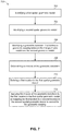
- FIG. 7 is a flow chart of a method for correcting warping in spatial audio in accordance with an implementation of the present disclosure
- FIG. 8 is a flow chart of a method for mapping a dynamic audio object in accordance with an implementation of the present disclosure
- FIGS. 10A and 10B illustrate example mapped values in accordance with an implementation of the present disclosure
- the systems and methods may compensate for geometric and velocity warping that may occur during rendering of spatial audio content authored due to a difference between the first spatial geometric model that the author uses to create the spatial audio content and the second spatial geometric model that represents how the sound will be produced when rendered.
- the systems and methods may compute a three dimensional (3D) transformation that defines a geometric warping resulting from the differences between spatial geometric models and may encode an inverse of the geometric warping into one of the spatial geometric models.
- 3D three dimensional
- the present solution may be utilized with any spatial audio rendering technology that uses physical speakers placed around the listener to achieve a specialization effect where the listener experiences the sound as originating from specified positions. Because the physical room geometry may not be known when the spatial audio content is authored, the content must be authored to a normalized room geometry that abstracts the room into a known layout.
- a static audio object represents a sound that will play back through a specific speaker (or audio channel).
- spatial audio content rendered to a static audio object defined as Front-Right will result in audio coming out of the Front-Right speaker, and only that speaker, if that speaker is present at the rendering stage. If the speaker is not present, the renderer will balance the sound across adjacent speakers, referred to as panning.
- the following criteria may be associated with a normalized room geometry in order to work as a spatial audio volumetric coordinate system.
- every static audio object supported by the spatial encoding format must be represented in the normalized room geometry. Because the normalized room geometry has no knowledge of what physical speaker may or may not be present in the physical room geometry, all speakers are assumed to be present.
- the conversion from a normalized room geometry to the physical room geometry results in a warping in geometric space, which, in turn, results in temporal warping of animated dynamic objects traversing the warped geometry over time.
- the normalized room geometry may specify a listener position at origin (0, 0, 0) and a front-left static object at position ( ⁇ 1, 1, 0).
- the listener is facing forward toward a front-center static object at position (0, ⁇ 1, 0) and the relative angle to the listener of the front-left static object is 45 degrees to the left relative to the listener, in the same horizontal plane as the listener.
- the front-left speaker corresponding to the front left static object in the normalized room geometry has a recommended placement of 30 degrees relative to the listener.
- variable warping may occur. If the author animated a sound in a perfect circle about the listener at a constant velocity, the result may not be a perfect circle and the velocity may not be constant.
- a warping in both space and time may occur (e.g., a space-time warping).
- the present solution compensates for this warping by applying an inverse of the warping to enable the spatial audio content to be rendered in the physical room geometry at the intended position relative to the listener as defined in the normalized room geometry that was used to author the spatial audio content.
- example views of a normalized room geometry 100 represent a room which is 2 units wide, 2 units deep, and 2 units tall, and having a listener 9 in the center of the room at geometric position (0,0,0). A distance to all “walls” of the room from listener is 1 unit.
- the model for the normalized room geometry 100 may include static audio objects such as one or more Front-Center (FC) speakers positioned at location (0,1,0), one or more Back-Center (BC) speakers positioned at location (0, ⁇ 1,0), one or more Left-Side (LS) speakers positioned at ( ⁇ 1,0,0), and one or more Right-Side (RS) speakers positioned at (1,0,0).
- static audio objects such as one or more Front-Left (FL) speakers in the corner at ( ⁇ 1,1,0) and one or more Front-Right (FR) speakers in the corner at (1,1,0), and so on.
- the model for the normalized room geometry 100 may also place static audio objects such as one or more upper and lower speakers (TopFrontLeft, TopFrontRight, TopBackLeft, TopBackRight, and corresponding four bottom speakers) at the center of each of the four ceiling and lower quadrants.
- the normalized room geometry 100 may vary from encoder to encoder.
- an example of a physical room geometry 200 (which may be referred to as a rendering model) in accordance with an implementation includes different positioning of each static audio object relative to the listener 9 , as compared to the normalized room geometry 100 of FIGS. 1A-1C .
- the geometric configuration of physical room geometry 200 demonstrate one of many possible differences in layout of the geometry between the physical room geometry and the normalized room geometry. In particular, any difference between any of the static audio objects between the two geometries can cause space and time warping of spatial audio content. For example, as compared to the normalized room geometry 100 of FIGS.
- the physical room geometry 200 may have static audio objects such as one or more front center speakers relatively closer to the listener 9 , and one or more front left speakers and front right speakers at different relative angles (e.g., placed at +/ ⁇ 30 degrees, respectively, relative to the listener 9 ), and one or more left side and right side speakers, respectively, in different relative positions with respect to the listener 9 .
- the physical room geometry 200 may have static audio objects such as one or more ceiling and floor speakers positioned closer to the listener 9 as compared to the normalized room geometry 100 of FIGS. 1A-1C .
- static audio objects such as one or more back speakers (e.g., back center (BC), back left, and back right) may be positioned physically further away from and/or at different angles relative to the listener 9 .
- the placement of each static audio object in the physical room geometry 200 may be based on, for example, recommended speaker positions and angles of speakers by a specific spatial audio encoder technology for an “optimal audio experience.”
- Geometric warping in the rendering of spatial audio content may be caused by the difference between the normalized room geometry 100 of FIGS. 1A-1C (e.g., the authoring model) and the physical room geometry 200 of FIGS. 2A-2C (the rendering model).
- the normalized room geometry 100 of FIGS. 1A-1C e.g., the authoring model
- the physical room geometry 200 of FIGS. 2A-2C the rendering model
- FIGS. 3A-3C For example, spatial audio content in the form of a sphere 300 about the listener 9 authored in the normalized room geometry 100 is illustrated in FIGS. 3A-3C .
- FIGS. 4A-4C illustrate an example of a geometric warping 400 that may occur when rendering the sphere 300 authored in the normalized room geometry 100 in a room with physical room geometry 200 .
- geometry warping may occur in order to guarantee that a location of each static audio object in the normalized room geometry 100 maps perfectly onto the corresponding static audio object in the physical room geometry 200 .
- rendering of this example of the spatial audio content in the physical room geometry 200 will result in the geometric warping 400 .
- FIG. 5A includes an example of a room with the expected physical room geometry 500 and an intended spatial audio content rendering 510 , e.g., a rendered sphere, representing a result of the present solution.
- FIGS. 5B and 5C includes the normalized room geometry 100 modified according to the present disclosure to include an inverse projection 520 (e.g., the 3D transformation, or the inverse of the geometric warping) of the intended spatial audio content rendering 510 , e.g., the sphere, into the normalized geometry 100 .
- This modification enables the expected physical room geometry 500 to properly and accurately render the intended spatial audio content rendering 510 , e.g., with a substantial reduction or elimination of time and/or space warping of the spatial audio content.
- the methods and systems of the present disclosure may compute the 3D transformation that defines the geometric warping that may occur between the expected physical room geometry and the normalized geometry and may encode the 3D transformation (e.g., an inverse of the geometric warping, or inverse geometric transform) into the normalized room geometry.
- the 3D transformation e.g., an inverse of the geometric warping, or inverse geometric transform
- an example computer device 602 for compensating for warping of 3D spatial audio may include an operating system 610 executed by processor 40 and/or memory 42 of computer device 602 .
- 3D spatial audio may include an ability to place audio sources about a listener in three dimensions, e.g., using x, y, z coordinates relative to the listener.
- Computer device 602 may include one or more applications 10 executed or processed by processor 40 and/or memory 42 of computer device 602 .
- Memory 42 of computer device 602 may be configured for storing data and/or computer-executable instructions defining and/or associated with operating system 610 , and processor 40 may execute operating system 610 .
- An example of memory 42 can include, but is not limited to, a type of memory usable by a computer, such as random access memory (RAM), read only memory (ROM), tapes, magnetic discs, optical discs, volatile memory, non-volatile memory, and any combination thereof.
- processor 40 can include, but is not limited to, any processor specially programmed as described herein, including a controller, microcontroller, application specific integrated circuit (ASIC), field programmable gate array (FPGA), system on chip (SoC), or other programmable logic or state machine.
- ASIC application specific integrated circuit
- FPGA field programmable gate array
- SoC system on chip
- Computer device 602 may include any mobile or fixed computer device, which may be connectable to a network.
- Computer device 602 may be, for example, a computer device such as a desktop or laptop or tablet computer, a cellular telephone, a gaming device, a mixed reality or virtual reality device, a music device, a television, a navigation system, a camera, a personal digital assistant (PDA), or a handheld device, or any other computer device having wired and/or wireless connection capability with one or more other devices.
- a computer device such as a desktop or laptop or tablet computer, a cellular telephone, a gaming device, a mixed reality or virtual reality device, a music device, a television, a navigation system, a camera, a personal digital assistant (PDA), or a handheld device, or any other computer device having wired and/or wireless connection capability with one or more other devices.
- PDA personal digital assistant
- An example user may include a developer writing a game.
- the developer may want an immersive audio experience and may use application 10 to access spatial audio API 20 to place sounds about a listener (e.g., a gamer playing the game) to improve an experience of the game.
- the developer may want the gamer to hear a gunshot off to the left on the horizon, or to hear footsteps of someone walking up behind them, or hear a voice of someone up on a balcony, and may use audio as the only cue (or in combination with a visual cue) to the gamer to look in the direction of the sound.
- the sound may have a 3-Dimensional position relative to the listener (e.g., a point of view of the gamer or a character playing the game).
- Application 10 may also allow a user to experience spatial audio.
- a user of application 10 may include a listener who experiences the immersive 3D audio during gameplay when listening on a device and/or environment that supports spatial 3D audio. The user may hear the gunshot on the ridge to the left, the footsteps walking behind them, the bad guy talking up on the balcony, and know exactly where that sound is coming from.
- VSS virtual surround sound
- HRTF head-related transfer function
- Other uses of application 10 may include virtual surround sound (VSS) using a head-related transfer function (HRTF) spatial encoder to place virtual speakers about a listener over headphones.
- the static objects may be virtualized into HRTF so the user may experience surround sound over headphones while watching a movie that was rendered in surround sound, or even full spatial audio of a movie with authored spatial audio or a game with spatial audio.
- Application 10 may communicate with at least one spatial audio application programming interface (API) 20 .
- Spatial audio API 20 may allow for the playback of audio via, for example, one or more speakers 12 , as either a static audio object assigned to any of the available static audio objects and/or dynamic audio objects generated by two or more static audio objects based on corresponding x, y, z position data.
- Spatial audio API 20 may expose any spatial geometry, such as normalized spatial geometry 100 and/or physical room spatial geometry 200 .
- Spatial geometries may include a specific layout of static audio objects relative to a listener as defined either by vertical and horizontal angles and distance to the listener, or by providing a room width, depth and height, along with x, y, z coordinates of the static audio objects within the volumetric space relative to the listener.
- Spatial geometries may be defined by requirements from an encoder. As such, a spatial geometry may vary from encoder to encoder.
- spatial audio API 20 may expose a common spatial geometry independent of any underlying spatial geometry requirements from encoders.
- Spatial audio API 20 may also expose a spatial geometry specified by a user (e.g., specifying the physical spatial geometry of the volumetric space which the audio will be consumed). When a user specifies a spatial geometry, spatial audio API 20 may also continue to expose a common spatial geometry and spatial audio API 20 may perform additional mapping between the common spatial geometry and the user defined spatial geometry prior to mapping to an encoder spatial geometry.
- a spatial geometry specified by a user e.g., specifying the physical spatial geometry of the volumetric space which the audio will be consumed.
- spatial audio API 20 may also continue to expose a common spatial geometry and spatial audio API 20 may perform additional mapping between the common spatial geometry and the user defined spatial geometry prior to mapping to an encoder spatial geometry.
- Spatial audio API 20 may accept room geometry input from one or more applications 10 and may process the room geometry input into a specific spatial audio encoder 38 .
- Spatial audio API 20 may communicate with a spatial audio encoder 38 that defines an encoder spatial geometry 26 .
- the encoder spatial geometry 26 may include a specific layout of a plurality of static audio objects 28 relative to a listener.
- the encoder spatial geometry 26 may be defined by vertical and horizontal angles of the static audio objects 28 and a relative distance from the static audio objects 28 to a listener.
- the encoder spatial geometry 26 may also be defined by providing a room width, depth, and height, and corresponding x, y, z coordinates of the static audio objects 28 within the volumetric space relative to a listener.
- Spatial audio API 20 may also determine an expected spatial geometry 30 of the room specified by application 10 .
- spatial audio API 20 may receive the geometry of the room from spatial audio API 20 .
- Spatial audio API 20 may have a mapping component 22 that maps the positions of the dynamic audio objects 32 of the expected spatial geometry 30 directly to positions of static audio object 28 in the encoder spatial geometry 26 when the x, y, z positions of the dynamic audio objects 32 align with the documented x, y, z positions of the static audio objects 28 .
- the mapping occurs regardless of any differences in spatial geometries between the encoder spatial geometry 26 and the expected spatial geometry 30 . Differences in static audio objects positions between geometries may cause stretching and compression (e.g., warping) of coordinate space between any various static audio objects, which may occur in three dimensional space as well.
- a geometric transform 35 may be identified that defines a geometric warping between the expected spatial geometry 30 and the encoder spatial geometry 26 .
- geometric transform 35 may be predicted by defining a geometry which corresponds to the encoder spatial geometry 26 .
- the space between them may be compressed during the mapping, however, those two static audio objects may also be further away from the listener, so the space may be stretched as well.
- Another example may include the distance remains the same where no stretching or compression occurs.
- Other examples may include one of the static audio objects is closer or further apart to the other, but at the same time one static object is closer to the listener while the other is further away.
- there may be a listener and two static objects with a potential for any combination of compression, stretching, and/or same on each of the line segments between the static objects and/or the static objects and the listener.
- each segment may stretch, compress, and/or stay the same.
- a complex 3D warping of the space contained within the mesh zone may be created.
- Warping may cause both spatial and temporal distortions when perceived over time. Spatial warping may be evidenced by a dynamic audio object placed at a specific distance and a specific angle from a listener in the first model and the dynamic audio object is also placed at the same x, y, z coordinates in the second model, but with different distance and/or angle than was originally authored in the first model.
- Temporal distortions may be evidenced by an animated path of a dynamic audio object over time, which in the first model may be authored on a path that traverses a perfect circle at a constant velocity and constant radius form a listener, but due to geometry warping, while still being placed at the same x, y, z positions over time, no longer has a constant velocity or a constant radius from the listener.
- spatial audio API 20 may also include a calculator component 24 that calculates an inverse geometric transform 34 that compensates for a geometric warping that may occur during the mapping of the dynamic audio objects 32 in the expected spatial geometry 30 to static audio objects 28 in the encoder spatial geometry 26 .
- Spatial audio API 20 may apply the inverse geometric transform 34 to the dynamic audio objects 32 and generate an expected rendered spatial geometry 36 .
- the expected rendered spatial geometry 36 may include new positions for the dynamic audio objects 32 in the expected rendered spatial geometry 36 so that the new positions are encoded based on the requirements of the encoder spatial geometry 26 .
- the expected rendered spatial geometry 36 may correct for geometric warping caused by differences between the encoder spatial geometry 26 and the expected spatial geometry 30 .
- a modeled sound may be created at static audio object 33 in an expected spatial geometry 30 .
- the actual sound outputted by one or more speakers 12 may differ from the modeled sound due to geometric warping that may have occurred because of differences between the encoder spatial geometry 26 and the expected spatial geometry 30 .
- the expected rendered spatial geometry 36 may be used by spatial audio API 20 when outputting the modeled sound, for example, through one or more speakers 12 so that the actual sound outputted by the speakers 12 corrects for the geometric warping between the encoder spatial geometry 26 and the expected spatial geometry 30 .
- Spatial audio API 20 may expose the expected rendered spatial geometry 36 to application 10 .
- application 10 may receive an expected rendered spatial geometry 36 that maintains an intent of the user while compensating for geometric warping based on the encoder spatial geometry 26 of the spatial audio encoder 38 .
- spatial audio rendering component 16 may render the spatial audio during playback of the rendered spatial geometry 36 .
- Spatial audio rendering component 16 may be on computer device 602 or another external device.
- a method 700 of correcting warping in spatial audio may be executed by an operating system 610 ( FIG. 1 ) on computer device 602 ( FIG. 1 ).
- method 700 may include identifying a first spatial geometric model.
- the first spatial geometric model may represent how sound may be produced in a first volumetric space.
- the first spatial geometric model may include a first set of static audio objects positioned relative to a fixed point.
- the front-left audio object might be at position ⁇ 10, ⁇ 15, 0, within a range of ⁇ 15 to 15 for each x, y, z coordinate.
- the first spatial geometric model may be the expected spatial geometry 30 ( FIG. 1 ) generated based on the received room geometry input from application 10 ( FIG. 1 ).
- a user of application 10 may define the range of the coordinate positions for the static audio objects and/or may define a geometry for the first spatial geometric model.
- method 700 may include identifying a second spatial geometric model.
- the second spatial geometric model may represent how sound may be produced in a second volumetric space that may be different from the first volumetric space.
- the second spatial geometric model may also include a second set of static audio objects positions relative to a fixed point.
- Each of the static audio objects within the second geometric model may be identified with coordinate positions within a second range of positions.
- the fixed point may be a listener represented at location (0, 0, 0) and the second geometric model may identify a range of valid positions for the second set of static audio objects relative to the listener.
- the range of valid positions for the second set of static audio objects may be different from the range of valid positions for the static audio objects in the first geometric model.
- the geometric relationship of the second geometric model may be different from the geometric relationship of the first geometric model.
- the fixed point may be a listener represented at location (0,0,0) and the first geometric model may identify a range of valid positions for the static audio objects relative to the listener.
- An example range may include ⁇ 1 to 1 for each x, y, z position for the static audio object, where one unit equals one meter.
- the second spatial geometric model may be the encoder spatial geometry 26 ( FIG. 1 ) specified by spatial audio encoder 38 ( FIG. 1 ).
- method 700 may include identify a geometric transform that defines a geometric warping between the first geometric model and the second geometric model.
- Spatial audio API 20 FIG. 1
- a front-left speaker in the first geometric model may be positioned at ⁇ 1, ⁇ 1, 0, with a range of ⁇ 1 to 1 for each x, y, z coordinate
- a front-left speaker in the second geometric model may be at position ⁇ 10, ⁇ 15, 0, with a range of ⁇ 15 to 15 for each x, y, z coordinate.
- the front-left speaker may be positioned at 45 degrees to the left of the listener and in the second geometric model, the front-left speaker may be positioned at 25 degrees.
- a warping may occur because the label speaker positions are aligned such that a point rendered at a same position of each speaker in the first geometric model will translate to the same position of that speaker in the second geometric model.
- the point ⁇ 1, 1, 0 in the first geometric model translates to point ⁇ 10, ⁇ 15, 0, in the example described, and the relative difference in position with respect to the listener defines one dimension of the warping, which is determined for all corresponding points between the models.
- method 700 may include determining an inverse of the geometric transform that compensates for the geometric transform.
- spatial audio API 20 may calculate an inverse of geometric transform 34 that compensates for a geometric warping that may occur between the first spatial geometric model and the second spatial geometric model.
- geometric transform 35 may be a prediction of the second spatial geometric model. The prediction may be based on, for example, user input or requirements from an encoder. Spatial audio API 20 may place points into the prediction of the second spatial geometric model and transform the placed points into the first spatial geometric model to calculate the inverse geometric transform 34 .
- method 700 may include defining a first location in the first spatial geometric model.
- the first location may relate to a dynamic audio object 32 ( FIG. 1 ) in the expected spatial geometry 30 .
- Spatial audio API 20 may identify the dynamic audio object 32 , for example, by room geometry input received by application 10 .
- a user of application 10 may place the dynamic audio object 32 in the expected spatial geometry 30 .
- method 700 may include applying the inverse of the geometric transform to the first location in the first spatial geometric model by mapping the first location to a second location in the second geometric model to correct for the geometric warping.
- spatial audio API 20 may map the position of the dynamic audio objects 32 of the first spatial geometric model directly to positions of static audio objects 28 in the second spatial geometric model when the dynamic audio objects 32 x, y, z positions align with the documented x, y, z positions of the static audio objects 28 .
- a method 800 for mapping a dynamic audio object between a first mesh ( FIG. 9A ) and a second mesh ( FIG. 9B ) associated with different spatial geometries may be executed by an operating system 610 ( FIG. 1 ) on computer device 602 ( FIG. 1 ).
- the method 800 is one example of a specific implementation of the present disclosure to compensate for warping between different spatial geometries in spatial audio.
- method 800 may include computing a first mesh of a first spatial geometric model.
- spatial audio API 20 FIG. 1
- spatial audio API 20 may determine a count of the static audio objects 28 in the encoder spatial geometry 26 and a count of the static audio objects 33 in the expected spatial geometry 30 and take the greater of the two. For any missing static audio objects in the encoder spatial geometry 26 and/or the expected spatial geometry 30 , spatial audio API 20 may generate positions which are symmetric to existing static audio objects in the corresponding geometry. For example, if one geometry has a center back static audio object, but the other geometry does not have a center back static audio object, spatial audio API 20 may generate a static audio object for the center back directly midpoint between back right and back left static objects for the geometry that does not have a center back static audio object.
- spatial audio API 20 may generate a mirror of the top speakers by reflecting the positions of the top speakers in the inverse plane.
- spatial audio API 20 is generating any additional static audio objects, symmetric angels and distances may be maintained.
- Spatial audio API 20 may generate a mesh for the expected spatial geometry 30 using all the static audio objects 33 in a listener plane to form a list of line segments.
- One implementation may include starting at any static object in listener plane, connect to next object.
- An example set of surround speakers may include, FrontLeft ⁇ FrontCenter ⁇ FrontRight ⁇ SideRight ⁇ BackRight ⁇ BackCenter ⁇ BackLeft ⁇ SideLeft ⁇ FrontLeft.
- spatial audio API 20 may connect to a corresponding upper speaker nearest the segment.
- segment FrontLeft ⁇ FrontCenter may connect to TopFrontLeft, which defines a single face of the mesh. If lower speakers are present, each segment may connect again to lower speakers, so Front ⁇ Left ⁇ FrontCenter ⁇ BottomFrontLeft.
- Top speakers may be connected to each other, or to a central generated center point to maintain polar symmetry, and down to surrounding speakers. By connecting the top and bottom speakers as described above, a solid mesh made up of just triangles may be created which completely surrounds the listener.
- An example mesh 910 of the expected spatial geometry 30 is illustrated in FIG. 9A .
- method 800 may include computing a second mesh of a second spatial geometric model.
- Spatial audio API 20 may compute a second mesh in the form of a surrounding mesh of the encoder spatial geometry 26 ( FIG. 1 ) for the static audio objects 28 in the encoder spatial geometry 26 .
- spatial audio API 20 may use all the static audio objects 28 in a listener plane to form a list of line segments. For example, spatial audio API 20 may start at any static audio object 28 in listener plane, connect to next object.
- An example set of surround speakers may include, FrontLeft ⁇ FrontCenter ⁇ FrontRight ⁇ SideRight ⁇ BackRight ⁇ BackCenter ⁇ BackLeft ⁇ SideLeft ⁇ FrontLeft.
- spatial audio API 20 may connect to a corresponding upper speaker nearest the segment.
- segment FrontLeft ⁇ FrontCenter may connect to TopFrontLeft, which defines a single face of the mesh. If lower speakers are present, each segment may connect again to lower speakers, so Front ⁇ Left ⁇ FrontCenter ⁇ BottomFrontLeft.
- Top speakers may be connected to each other, or to a central generated center point to maintain polar symmetry and down to surrounding speakers. By connecting the top and bottom speakers as described above, a solid mesh made up of just triangles may be created which completely surrounds the listener.
- An example mesh 920 of the encoder spatial geometry is illustrated in FIG. 9B .
- first mesh and the second mesh each have a same number of faces, which directly correspond to a same ordered mesh face on the other mesh.
- face 1 on mesh 1 is defined by FrontLeft, FrontCenter and TopFrontLeft
- face 1 on mesh 2 is defined the same by FrontLeft, FrontCenter and TopFrontLeft.
- method 800 may include mapping a dynamic audio object relative to the first mesh to a new translated point in the second mesh.
- spatial audio API 20 may map a dynamic audio object 32 from the expected spatial geometry 30 to a new translated point in the encoder spatial geometry 26 .
- One implementation for mapping a dynamic audio object 32 (D 1 ) from the first mesh to a new translated point (D 2 ) in the second mesh may include spatial audio API 20 defining a first line (L 1 ) in the first mesh from origin (0, 0, 0) to D 1 and computing an intersection face (face F 1 ) of the first mesh by using the first line L 1 and an intersection point P 1 .
- Spatial audio API 20 may also identify a second face (F 2 ) in the second mesh that directly corresponds to face F 1 in the first mesh.
- Spatial audio API 20 may map Point P 1 in face F 1 into a new mapped intersection point P 2 in face F 2 while maintaining relative position face F 1 and face F 2 .
- mapping point P 1 to P 2 may include spatial audio API 20 defining a triangle for first face in the first mesh as A 1 , B 1 , C 1 , where point P 1 is the intersection point contained within the triangle for the first face, as illustrated in FIG. 10A .
- Intersection point P 1 may be mapped to an intersection point P 2 and scaled to get point D 2 , as illustrated in FIG. 11B .
- Spatial audio API 20 may also define a triangle for second face in the second mesh as A 2 , B 2 , C 2 , as illustrated in FIG. 10B .
- Spatial audio API 20 may also define line A as point A 1 to point P 1 and line B as Point B 1 to point C 1 and may find the intersection of line A and line B at point M 1 , as illustrated in FIG. 11A .
- Line M 1 will line on the line segment B 1 ⁇ C 1 .
- Spatial audio API 20 may compute scaleB 1 as (magnitude(B 1 ⁇ M 1 )/(magnitude(B 1 ⁇ C 1 ).
- Spatial audio API 20 may compute scaleA 1 as (magnitude(A 1 ⁇ P 1 )/(magnitude(A 1 ⁇ M 1 ).
- computer device 602 may include processor 40 for carrying out processing functions associated with one or more of components and functions described herein.
- processor 40 can include a single or multiple set of processors or multi-core processors.
- processor 40 can be implemented as an integrated processing system and/or a distributed processing system.
- Computer device 602 may further include memory 42 , such as for storing local versions of applications being executed by processor 40 .
- Memory 42 can include a type of memory usable by a computer, such as random access memory (RAM), read only memory (ROM), tapes, magnetic discs, optical discs, volatile memory, non-volatile memory, and any combination thereof.
- processor 40 and memory 42 may include and execute operating system 610 ( FIG. 1 ).
- computer device 602 may include a communications component 46 that provides for establishing and maintaining communications with one or more parties utilizing hardware, software, and services as described herein.
- Communications component 46 may carry communications between components on computer device 602 , as well as between computer device 602 and external devices, such as devices located across a communications network and/or devices serially or locally connected to computer device 602 .
- communications component 46 may include one or more buses, and may further include transmit chain components and receive chain components associated with a transmitter and receiver, respectively, operable for interfacing with external devices.
- computer device 602 may include a data store 48 , which can be any suitable combination of hardware and/or software, that provides for mass storage of information, databases, and programs employed in connection with implementations described herein.
- data store 48 may be a data repository for applications 10 ( FIG. 1 ), spatial audio API 20 ( FIG. 1 ), spatial audio encoder 38 ( FIG. 1 ) and/or spatial audio rendering component 16 ( FIG. 1 ).
- Computer device 602 may also include a user interface component 50 operable to receive inputs from a user of computer device 602 and further operable to generate outputs for presentation to the user.
- User interface component 50 may include one or more input devices, including but not limited to a keyboard, a number pad, a mouse, a touch-sensitive display, a navigation key, a function key, a microphone, a voice recognition component, any other mechanism capable of receiving an input from a user, or any combination thereof.
- user interface component 50 may include one or more output devices, including but not limited to a display, a speaker, a haptic feedback mechanism, a printer, any other mechanism capable of presenting an output to a user, or any combination thereof.
- user interface component 50 may transmit and/or receive messages corresponding to the operation of applications 10 , spatial audio API 20 , spatial audio encoder 38 and/or spatial audio rendering component 16 .
- processor 40 executes applications 10 , spatial audio API 20 , spatial audio encoder 38 , and/or spatial audio rendering component 16 , and memory 42 or data store 48 may store them.
- a component may be, but is not limited to being, a process running on a processor, a processor, an object, an executable, a thread of execution, a program, and/or a computer.
- an application running on a computer device and the computer device can be a component.
- One or more components can reside within a process and/or thread of execution and a component may be localized on one computer and/or distributed between two or more computers.
- these components can execute from various computer readable media having various data structures stored thereon.
- the components may communicate by way of local and/or remote processes such as in accordance with a signal having one or more data packets, such as data from one component interacting with another component in a local system, distributed system, and/or across a network such as the Internet with other systems by way of the signal.
- a signal having one or more data packets, such as data from one component interacting with another component in a local system, distributed system, and/or across a network such as the Internet with other systems by way of the signal.
- a wireless device may be a cellular telephone, a satellite phone, a cordless telephone, a Session Initiation Protocol (SIP) phone, a wireless local loop (WLL) station, a personal digital assistant (PDA), a handheld device having wireless connection capability, a computer device, a mixed reality or virtual reality device, or other processing devices connected to a wireless modem.
- SIP Session Initiation Protocol
- WLL wireless local loop
- PDA personal digital assistant
- the term “or” is intended to mean an inclusive “or” rather than an exclusive “or.” That is, unless specified otherwise, or clear from the context, the phrase “X employs A or B” is intended to mean any of the natural inclusive permutations. That is, the phrase “X employs A or B” is satisfied by any of the following instances: X employs A; X employs B; or X employs both A and B.
- the articles “a” and “an” as used in this application and the appended claims should generally be construed to mean “one or more” unless specified otherwise or clear from the context to be directed to a singular form.
- DSP digital signal processor
- ASIC application specific integrated circuit
- FPGA field programmable gate array
- a general-purpose processor may be a microprocessor, but, in the alternative, the processor may be any conventional processor, controller, microcontroller, or state machine.
- a processor may also be implemented as a combination of computer devices, e.g., a combination of a DSP and a microprocessor, a plurality of microprocessors, one or more microprocessors in conjunction with a DSP core, or any other such configuration. Additionally, at least one processor may comprise one or more components operable to perform one or more of the steps and/or actions described above.
- a software module may reside in RAM memory, flash memory, ROM memory, EPROM memory, EEPROM memory, registers, a hard disk, a removable disk, a CD-ROM, or any other form of storage medium known in the art.
- An exemplary storage medium may be coupled to the processor, such that the processor can read information from, and write information to, the storage medium.
- the storage medium may be integral to the processor.
- the processor and the storage medium may reside in an ASIC. Additionally, the ASIC may reside in a user terminal.
- processor and the storage medium may reside as discrete components in a user terminal. Additionally, in some implementations, the steps and/or actions of a method or algorithm may reside as one or any combination or set of codes and/or instructions on a machine readable medium and/or computer readable medium, which may be incorporated into a computer program product.
- the functions described may be implemented in hardware, software, firmware, or any combination thereof. If implemented in software, the functions may be stored or transmitted as one or more instructions or code on a computer-readable medium.
- Computer-readable media includes both computer storage media and communication media including any medium that facilitates transfer of a computer program from one place to another.
- a storage medium may be any available media that can be accessed by a computer.
- such computer-readable media can comprise RAM, ROM, EEPROM, CD-ROM or other optical disk storage, magnetic disk storage or other magnetic storage devices, or any other medium that can be used to carry or store desired program code in the form of instructions or data structures and that can be accessed by a computer.
- Disk and disc includes compact disc (CD), laser disc, optical disc, digital versatile disc (DVD), floppy disk and Blu-ray disc where disks usually reproduce data magnetically, while discs usually reproduce data optically with lasers. Combinations of the above should also be included within the scope of computer-readable media.
Landscapes
- Engineering & Computer Science (AREA)
- Signal Processing (AREA)
- Physics & Mathematics (AREA)
- Acoustics & Sound (AREA)
- Stereophonic System (AREA)
- Multimedia (AREA)
- Computational Linguistics (AREA)
- Health & Medical Sciences (AREA)
- Audiology, Speech & Language Pathology (AREA)
- Human Computer Interaction (AREA)
Abstract
Description
Claims (20)
Priority Applications (2)
| Application Number | Priority Date | Filing Date | Title |
|---|---|---|---|
| US15/606,375 US10721578B2 (en) | 2017-01-06 | 2017-05-26 | Spatial audio warp compensator |
| PCT/US2017/068846 WO2018128911A1 (en) | 2017-01-06 | 2017-12-29 | Spatial audio warp compensator |
Applications Claiming Priority (2)
| Application Number | Priority Date | Filing Date | Title |
|---|---|---|---|
| US201762443328P | 2017-01-06 | 2017-01-06 | |
| US15/606,375 US10721578B2 (en) | 2017-01-06 | 2017-05-26 | Spatial audio warp compensator |
Publications (2)
| Publication Number | Publication Date |
|---|---|
| US20180197551A1 US20180197551A1 (en) | 2018-07-12 |
| US10721578B2 true US10721578B2 (en) | 2020-07-21 |
Family
ID=62783380
Family Applications (1)
| Application Number | Title | Priority Date | Filing Date |
|---|---|---|---|
| US15/606,375 Active 2037-06-19 US10721578B2 (en) | 2017-01-06 | 2017-05-26 | Spatial audio warp compensator |
Country Status (2)
| Country | Link |
|---|---|
| US (1) | US10721578B2 (en) |
| WO (1) | WO2018128911A1 (en) |
Families Citing this family (5)
| Publication number | Priority date | Publication date | Assignee | Title |
|---|---|---|---|---|
| US10327089B2 (en) * | 2015-04-14 | 2019-06-18 | Dsp4You Ltd. | Positioning an output element within a three-dimensional environment |
| BR112019021897A2 (en) * | 2017-04-25 | 2020-05-26 | Sony Corporation | SIGNAL PROCESSING DEVICE AND METHOD, AND, PROGRAM |
| US11393483B2 (en) * | 2018-01-26 | 2022-07-19 | Lg Electronics Inc. | Method for transmitting and receiving audio data and apparatus therefor |
| GB2612173A (en) * | 2021-09-21 | 2023-04-26 | Apple Inc | Determining a virtual listening environment |
| US20230188893A1 (en) * | 2021-12-10 | 2023-06-15 | Harman International Industries, Incorporated | Loudspeaker system for arbitrary sound direction rendering |
Citations (13)
| Publication number | Priority date | Publication date | Assignee | Title |
|---|---|---|---|---|
| US6694033B1 (en) | 1997-06-17 | 2004-02-17 | British Telecommunications Public Limited Company | Reproduction of spatialized audio |
| US20080025639A1 (en) * | 2006-07-31 | 2008-01-31 | Simon Widdowson | Image dominant line determination and use |
| US20080101711A1 (en) | 2006-10-26 | 2008-05-01 | Antonius Kalker | Rendering engine for forming an unwarped reproduction of stored content from warped content |
| US20090147975A1 (en) | 2007-12-06 | 2009-06-11 | Harman International Industries, Incorporated | Spatial processing stereo system |
| US7720212B1 (en) | 2004-07-29 | 2010-05-18 | Hewlett-Packard Development Company, L.P. | Spatial audio conferencing system |
| US20120194516A1 (en) * | 2011-01-31 | 2012-08-02 | Microsoft Corporation | Three-Dimensional Environment Reconstruction |
| US8374365B2 (en) | 2006-05-17 | 2013-02-12 | Creative Technology Ltd | Spatial audio analysis and synthesis for binaural reproduction and format conversion |
| US20130083173A1 (en) * | 2011-09-30 | 2013-04-04 | Kevin A. Geisner | Virtual spectator experience with a personal audio/visual apparatus |
| US20140016802A1 (en) * | 2012-07-16 | 2014-01-16 | Qualcomm Incorporated | Loudspeaker position compensation with 3d-audio hierarchical coding |
| US20140270320A1 (en) | 2013-03-15 | 2014-09-18 | Richard O'Polka | Portable sound system |
| US20150131824A1 (en) | 2012-04-02 | 2015-05-14 | Sonicemotion Ag | Method for high quality efficient 3d sound reproduction |
| US20150189455A1 (en) | 2013-12-30 | 2015-07-02 | Aliphcom | Transformation of multiple sound fields to generate a transformed reproduced sound field including modified reproductions of the multiple sound fields |
| US9338574B2 (en) | 2011-06-30 | 2016-05-10 | Thomson Licensing | Method and apparatus for changing the relative positions of sound objects contained within a Higher-Order Ambisonics representation |
-
2017
- 2017-05-26 US US15/606,375 patent/US10721578B2/en active Active
- 2017-12-29 WO PCT/US2017/068846 patent/WO2018128911A1/en active Application Filing
Patent Citations (13)
| Publication number | Priority date | Publication date | Assignee | Title |
|---|---|---|---|---|
| US6694033B1 (en) | 1997-06-17 | 2004-02-17 | British Telecommunications Public Limited Company | Reproduction of spatialized audio |
| US7720212B1 (en) | 2004-07-29 | 2010-05-18 | Hewlett-Packard Development Company, L.P. | Spatial audio conferencing system |
| US8374365B2 (en) | 2006-05-17 | 2013-02-12 | Creative Technology Ltd | Spatial audio analysis and synthesis for binaural reproduction and format conversion |
| US20080025639A1 (en) * | 2006-07-31 | 2008-01-31 | Simon Widdowson | Image dominant line determination and use |
| US20080101711A1 (en) | 2006-10-26 | 2008-05-01 | Antonius Kalker | Rendering engine for forming an unwarped reproduction of stored content from warped content |
| US20090147975A1 (en) | 2007-12-06 | 2009-06-11 | Harman International Industries, Incorporated | Spatial processing stereo system |
| US20120194516A1 (en) * | 2011-01-31 | 2012-08-02 | Microsoft Corporation | Three-Dimensional Environment Reconstruction |
| US9338574B2 (en) | 2011-06-30 | 2016-05-10 | Thomson Licensing | Method and apparatus for changing the relative positions of sound objects contained within a Higher-Order Ambisonics representation |
| US20130083173A1 (en) * | 2011-09-30 | 2013-04-04 | Kevin A. Geisner | Virtual spectator experience with a personal audio/visual apparatus |
| US20150131824A1 (en) | 2012-04-02 | 2015-05-14 | Sonicemotion Ag | Method for high quality efficient 3d sound reproduction |
| US20140016802A1 (en) * | 2012-07-16 | 2014-01-16 | Qualcomm Incorporated | Loudspeaker position compensation with 3d-audio hierarchical coding |
| US20140270320A1 (en) | 2013-03-15 | 2014-09-18 | Richard O'Polka | Portable sound system |
| US20150189455A1 (en) | 2013-12-30 | 2015-07-02 | Aliphcom | Transformation of multiple sound fields to generate a transformed reproduced sound field including modified reproductions of the multiple sound fields |
Non-Patent Citations (4)
| Title |
|---|
| "International Search Report and Written Opinion Issued in PCT Application No. PCT/US2017/068846", dated Mar. 9, 2018, 11 Pages. |
| Farina, et al., "Spatial Equalization of Sound Systems in Cars", In 15th International Conference on Audio Engineering Society, Oct. 1, 1998, 17 pages. |
| Gallo, et al., "3D-Audio Matting, Post-editing and Re-rendering from Field Recordings", In Journal of EURASIP Journal on Advances in Signal Processing, Dec. 1, 2007, pp. 1-14. |
| Mehra et al., "Wave-based sound propagation in large open scenes using an equivalent source formulation", Apr. 1, 2013 ACM Transactions on Graphics, vol. 32 Issue 2, Apr. 2013; Article No. 19. * |
Also Published As
| Publication number | Publication date |
|---|---|
| WO2018128911A1 (en) | 2018-07-12 |
| US20180197551A1 (en) | 2018-07-12 |
Similar Documents
| Publication | Publication Date | Title |
|---|---|---|
| US10721578B2 (en) | Spatial audio warp compensator | |
| US9197979B2 (en) | Object-based audio system using vector base amplitude panning | |
| US20200367008A1 (en) | System and method for rendering virtual sound sources | |
| US9888333B2 (en) | Three-dimensional audio rendering techniques | |
| CN110545887B (en) | Streaming of augmented/virtual reality space audio/video | |
| US10708707B2 (en) | Audio processing apparatus and method and program | |
| US11429340B2 (en) | Audio capture and rendering for extended reality experiences | |
| US10075797B2 (en) | Matrix decoder with constant-power pairwise panning | |
| US10278001B2 (en) | Multiple listener cloud render with enhanced instant replay | |
| US20220070606A1 (en) | Spatially-bounded audio elements with interior and exterior representations | |
| CN106448687B (en) | Audio production and decoded method and apparatus | |
| US10667074B2 (en) | Game streaming with spatial audio | |
| US11902769B2 (en) | Methods, apparatus and systems for representation, encoding, and decoding of discrete directivity data | |
| TW201937944A (en) | Apparatuses for converting an object position of an audio object, audio stream provider, audio content production system, audio playback apparatus, methods and computer programs | |
| US11750998B2 (en) | Controlling rendering of audio data | |
| US20240114312A1 (en) | Rendering interface for audio data in extended reality systems | |
| US20180220252A1 (en) | Spectator audio and video repositioning | |
| JP2023549758A (en) | Consistency of acoustic and visual scenes | |
| KR20090035894A (en) | Method and apparatus for genarating 3-dimensional image data | |
| Dantele et al. | Implementation of mpeg-4 audio nodes in an interactive virtual 3d environment | |
| CN114128312A (en) | Audio rendering for low frequency effects | |
| KR20240052967A (en) | Device and Method of Object-based Spatial Audio Mastering | |
| Schwark et al. | Audiovisual Virtual Environments: Enabling Realtime Rendering of Early Reflections by Scene Graph Simplification |
Legal Events
| Date | Code | Title | Description |
|---|---|---|---|
| AS | Assignment |
Owner name: MICROSOFT TECHNOLOGY LICENSING, LLC, WASHINGTON Free format text: ASSIGNMENT OF ASSIGNORS INTEREST;ASSIGNORS:MCDOWELL, BRIAN;EDRY, PHILIP ANDREW;HEITKAMP, ROBERT NORMAN;SIGNING DATES FROM 20170503 TO 20170525;REEL/FRAME:042516/0004 |
|
| STPP | Information on status: patent application and granting procedure in general |
Free format text: RESPONSE TO NON-FINAL OFFICE ACTION ENTERED AND FORWARDED TO EXAMINER |
|
| STPP | Information on status: patent application and granting procedure in general |
Free format text: FINAL REJECTION MAILED |
|
| STPP | Information on status: patent application and granting procedure in general |
Free format text: RESPONSE AFTER FINAL ACTION FORWARDED TO EXAMINER |
|
| STPP | Information on status: patent application and granting procedure in general |
Free format text: ADVISORY ACTION MAILED |
|
| STPP | Information on status: patent application and granting procedure in general |
Free format text: DOCKETED NEW CASE - READY FOR EXAMINATION |
|
| STPP | Information on status: patent application and granting procedure in general |
Free format text: NON FINAL ACTION MAILED |
|
| STPP | Information on status: patent application and granting procedure in general |
Free format text: RESPONSE TO NON-FINAL OFFICE ACTION ENTERED AND FORWARDED TO EXAMINER |
|
| STPP | Information on status: patent application and granting procedure in general |
Free format text: PUBLICATIONS -- ISSUE FEE PAYMENT RECEIVED |
|
| STCF | Information on status: patent grant |
Free format text: PATENTED CASE |
|
| MAFP | Maintenance fee payment |
Free format text: PAYMENT OF MAINTENANCE FEE, 4TH YEAR, LARGE ENTITY (ORIGINAL EVENT CODE: M1551); ENTITY STATUS OF PATENT OWNER: LARGE ENTITY Year of fee payment: 4 |