US10712005B2 - Ceramic matrix composite manufacturing - Google Patents
Ceramic matrix composite manufacturing Download PDFInfo
- Publication number
- US10712005B2 US10712005B2 US15/650,400 US201715650400A US10712005B2 US 10712005 B2 US10712005 B2 US 10712005B2 US 201715650400 A US201715650400 A US 201715650400A US 10712005 B2 US10712005 B2 US 10712005B2
- Authority
- US
- United States
- Prior art keywords
- chamber
- gaseous
- mitigation agent
- various embodiments
- introducing
- Prior art date
- Legal status (The legal status is an assumption and is not a legal conclusion. Google has not performed a legal analysis and makes no representation as to the accuracy of the status listed.)
- Active, expires
Links
- 238000004519 manufacturing process Methods 0.000 title claims abstract description 23
- 239000011153 ceramic matrix composite Substances 0.000 title claims abstract description 16
- 230000000116 mitigating effect Effects 0.000 claims abstract description 44
- 239000003795 chemical substances by application Substances 0.000 claims abstract description 43
- 239000002243 precursor Substances 0.000 claims abstract description 43
- JLUFWMXJHAVVNN-UHFFFAOYSA-N methyltrichlorosilane Chemical compound C[Si](Cl)(Cl)Cl JLUFWMXJHAVVNN-UHFFFAOYSA-N 0.000 claims abstract description 20
- 239000005055 methyl trichlorosilane Substances 0.000 claims abstract description 16
- UFHFLCQGNIYNRP-UHFFFAOYSA-N Hydrogen Chemical compound [H][H] UFHFLCQGNIYNRP-UHFFFAOYSA-N 0.000 claims abstract description 14
- 238000000034 method Methods 0.000 claims description 30
- 239000007789 gas Substances 0.000 claims description 20
- 239000000758 substrate Substances 0.000 claims description 7
- 238000011144 upstream manufacturing Methods 0.000 claims description 7
- 238000006243 chemical reaction Methods 0.000 abstract description 12
- 239000006227 byproduct Substances 0.000 abstract description 9
- 230000015572 biosynthetic process Effects 0.000 abstract description 8
- 238000000280 densification Methods 0.000 abstract description 2
- 238000005229 chemical vapour deposition Methods 0.000 description 7
- 239000000463 material Substances 0.000 description 7
- 230000008901 benefit Effects 0.000 description 6
- OKTJSMMVPCPJKN-UHFFFAOYSA-N Carbon Chemical compound [C] OKTJSMMVPCPJKN-UHFFFAOYSA-N 0.000 description 5
- 230000008569 process Effects 0.000 description 5
- HBMJWWWQQXIZIP-UHFFFAOYSA-N silicon carbide Chemical compound [Si+]#[C-] HBMJWWWQQXIZIP-UHFFFAOYSA-N 0.000 description 5
- 238000001764 infiltration Methods 0.000 description 4
- 230000008595 infiltration Effects 0.000 description 4
- 230000014759 maintenance of location Effects 0.000 description 4
- 125000006850 spacer group Chemical group 0.000 description 4
- 229910052799 carbon Inorganic materials 0.000 description 3
- 238000004891 communication Methods 0.000 description 3
- 239000002131 composite material Substances 0.000 description 3
- BUMGIEFFCMBQDG-UHFFFAOYSA-N dichlorosilicon Chemical compound Cl[Si]Cl BUMGIEFFCMBQDG-UHFFFAOYSA-N 0.000 description 3
- 239000011148 porous material Substances 0.000 description 3
- 238000010926 purge Methods 0.000 description 3
- 229910010271 silicon carbide Inorganic materials 0.000 description 3
- PPDADIYYMSXQJK-UHFFFAOYSA-N trichlorosilicon Chemical compound Cl[Si](Cl)Cl PPDADIYYMSXQJK-UHFFFAOYSA-N 0.000 description 3
- 229910004721 HSiCl3 Inorganic materials 0.000 description 2
- IJOOHPMOJXWVHK-UHFFFAOYSA-N chlorotrimethylsilane Chemical compound C[Si](C)(C)Cl IJOOHPMOJXWVHK-UHFFFAOYSA-N 0.000 description 2
- 238000000151 deposition Methods 0.000 description 2
- 230000008021 deposition Effects 0.000 description 2
- 238000005137 deposition process Methods 0.000 description 2
- 229910002804 graphite Inorganic materials 0.000 description 2
- 239000010439 graphite Substances 0.000 description 2
- 150000003254 radicals Chemical class 0.000 description 2
- 239000011435 rock Substances 0.000 description 2
- ZDHXKXAHOVTTAH-UHFFFAOYSA-N trichlorosilane Chemical compound Cl[SiH](Cl)Cl ZDHXKXAHOVTTAH-UHFFFAOYSA-N 0.000 description 2
- 229910015844 BCl3 Inorganic materials 0.000 description 1
- 238000009825 accumulation Methods 0.000 description 1
- 230000006978 adaptation Effects 0.000 description 1
- 238000000429 assembly Methods 0.000 description 1
- 230000000712 assembly Effects 0.000 description 1
- 239000000969 carrier Substances 0.000 description 1
- 239000003153 chemical reaction reagent Substances 0.000 description 1
- 238000004140 cleaning Methods 0.000 description 1
- 150000001875 compounds Chemical class 0.000 description 1
- 230000006835 compression Effects 0.000 description 1
- 238000007906 compression Methods 0.000 description 1
- 238000010276 construction Methods 0.000 description 1
- 230000008878 coupling Effects 0.000 description 1
- 238000010168 coupling process Methods 0.000 description 1
- 238000005859 coupling reaction Methods 0.000 description 1
- 125000004122 cyclic group Chemical group 0.000 description 1
- 230000007423 decrease Effects 0.000 description 1
- 230000001627 detrimental effect Effects 0.000 description 1
- 238000010586 diagram Methods 0.000 description 1
- LIKFHECYJZWXFJ-UHFFFAOYSA-N dimethyldichlorosilane Chemical compound C[Si](C)(Cl)Cl LIKFHECYJZWXFJ-UHFFFAOYSA-N 0.000 description 1
- 238000009826 distribution Methods 0.000 description 1
- 239000000835 fiber Substances 0.000 description 1
- 231100001261 hazardous Toxicity 0.000 description 1
- 238000010438 heat treatment Methods 0.000 description 1
- 230000003137 locomotive effect Effects 0.000 description 1
- 230000037361 pathway Effects 0.000 description 1
- 239000000376 reactant Substances 0.000 description 1
- 230000004044 response Effects 0.000 description 1
- 239000000126 substance Substances 0.000 description 1
- FAQYAMRNWDIXMY-UHFFFAOYSA-N trichloroborane Chemical compound ClB(Cl)Cl FAQYAMRNWDIXMY-UHFFFAOYSA-N 0.000 description 1
- 239000005051 trimethylchlorosilane Substances 0.000 description 1
- XLYOFNOQVPJJNP-UHFFFAOYSA-N water Chemical compound O XLYOFNOQVPJJNP-UHFFFAOYSA-N 0.000 description 1
Images


Classifications
-
- C—CHEMISTRY; METALLURGY
- C04—CEMENTS; CONCRETE; ARTIFICIAL STONE; CERAMICS; REFRACTORIES
- C04B—LIME, MAGNESIA; SLAG; CEMENTS; COMPOSITIONS THEREOF, e.g. MORTARS, CONCRETE OR LIKE BUILDING MATERIALS; ARTIFICIAL STONE; CERAMICS; REFRACTORIES; TREATMENT OF NATURAL STONE
- C04B35/00—Shaped ceramic products characterised by their composition; Ceramics compositions; Processing powders of inorganic compounds preparatory to the manufacturing of ceramic products
- C04B35/71—Ceramic products containing macroscopic reinforcing agents
- C04B35/78—Ceramic products containing macroscopic reinforcing agents containing non-metallic materials
- C04B35/80—Fibres, filaments, whiskers, platelets, or the like
-
- C—CHEMISTRY; METALLURGY
- C04—CEMENTS; CONCRETE; ARTIFICIAL STONE; CERAMICS; REFRACTORIES
- C04B—LIME, MAGNESIA; SLAG; CEMENTS; COMPOSITIONS THEREOF, e.g. MORTARS, CONCRETE OR LIKE BUILDING MATERIALS; ARTIFICIAL STONE; CERAMICS; REFRACTORIES; TREATMENT OF NATURAL STONE
- C04B35/00—Shaped ceramic products characterised by their composition; Ceramics compositions; Processing powders of inorganic compounds preparatory to the manufacturing of ceramic products
- C04B35/515—Shaped ceramic products characterised by their composition; Ceramics compositions; Processing powders of inorganic compounds preparatory to the manufacturing of ceramic products based on non-oxide ceramics
- C04B35/56—Shaped ceramic products characterised by their composition; Ceramics compositions; Processing powders of inorganic compounds preparatory to the manufacturing of ceramic products based on non-oxide ceramics based on carbides or oxycarbides
- C04B35/565—Shaped ceramic products characterised by their composition; Ceramics compositions; Processing powders of inorganic compounds preparatory to the manufacturing of ceramic products based on non-oxide ceramics based on carbides or oxycarbides based on silicon carbide
-
- C—CHEMISTRY; METALLURGY
- C04—CEMENTS; CONCRETE; ARTIFICIAL STONE; CERAMICS; REFRACTORIES
- C04B—LIME, MAGNESIA; SLAG; CEMENTS; COMPOSITIONS THEREOF, e.g. MORTARS, CONCRETE OR LIKE BUILDING MATERIALS; ARTIFICIAL STONE; CERAMICS; REFRACTORIES; TREATMENT OF NATURAL STONE
- C04B35/00—Shaped ceramic products characterised by their composition; Ceramics compositions; Processing powders of inorganic compounds preparatory to the manufacturing of ceramic products
- C04B35/622—Forming processes; Processing powders of inorganic compounds preparatory to the manufacturing of ceramic products
- C04B35/626—Preparing or treating the powders individually or as batches ; preparing or treating macroscopic reinforcing agents for ceramic products, e.g. fibres; mechanical aspects section B
- C04B35/628—Coating the powders or the macroscopic reinforcing agents
- C04B35/62802—Powder coating materials
- C04B35/62828—Non-oxide ceramics
-
- C04B35/806—
-
- C—CHEMISTRY; METALLURGY
- C04—CEMENTS; CONCRETE; ARTIFICIAL STONE; CERAMICS; REFRACTORIES
- C04B—LIME, MAGNESIA; SLAG; CEMENTS; COMPOSITIONS THEREOF, e.g. MORTARS, CONCRETE OR LIKE BUILDING MATERIALS; ARTIFICIAL STONE; CERAMICS; REFRACTORIES; TREATMENT OF NATURAL STONE
- C04B35/00—Shaped ceramic products characterised by their composition; Ceramics compositions; Processing powders of inorganic compounds preparatory to the manufacturing of ceramic products
- C04B35/71—Ceramic products containing macroscopic reinforcing agents
- C04B35/78—Ceramic products containing macroscopic reinforcing agents containing non-metallic materials
- C04B35/80—Fibres, filaments, whiskers, platelets, or the like
- C04B35/83—Carbon fibres in a carbon matrix
-
- C—CHEMISTRY; METALLURGY
- C23—COATING METALLIC MATERIAL; COATING MATERIAL WITH METALLIC MATERIAL; CHEMICAL SURFACE TREATMENT; DIFFUSION TREATMENT OF METALLIC MATERIAL; COATING BY VACUUM EVAPORATION, BY SPUTTERING, BY ION IMPLANTATION OR BY CHEMICAL VAPOUR DEPOSITION, IN GENERAL; INHIBITING CORROSION OF METALLIC MATERIAL OR INCRUSTATION IN GENERAL
- C23C—COATING METALLIC MATERIAL; COATING MATERIAL WITH METALLIC MATERIAL; SURFACE TREATMENT OF METALLIC MATERIAL BY DIFFUSION INTO THE SURFACE, BY CHEMICAL CONVERSION OR SUBSTITUTION; COATING BY VACUUM EVAPORATION, BY SPUTTERING, BY ION IMPLANTATION OR BY CHEMICAL VAPOUR DEPOSITION, IN GENERAL
- C23C16/00—Chemical coating by decomposition of gaseous compounds, without leaving reaction products of surface material in the coating, i.e. chemical vapour deposition [CVD] processes
- C23C16/04—Coating on selected surface areas, e.g. using masks
- C23C16/045—Coating cavities or hollow spaces, e.g. interior of tubes; Infiltration of porous substrates
-
- C—CHEMISTRY; METALLURGY
- C23—COATING METALLIC MATERIAL; COATING MATERIAL WITH METALLIC MATERIAL; CHEMICAL SURFACE TREATMENT; DIFFUSION TREATMENT OF METALLIC MATERIAL; COATING BY VACUUM EVAPORATION, BY SPUTTERING, BY ION IMPLANTATION OR BY CHEMICAL VAPOUR DEPOSITION, IN GENERAL; INHIBITING CORROSION OF METALLIC MATERIAL OR INCRUSTATION IN GENERAL
- C23C—COATING METALLIC MATERIAL; COATING MATERIAL WITH METALLIC MATERIAL; SURFACE TREATMENT OF METALLIC MATERIAL BY DIFFUSION INTO THE SURFACE, BY CHEMICAL CONVERSION OR SUBSTITUTION; COATING BY VACUUM EVAPORATION, BY SPUTTERING, BY ION IMPLANTATION OR BY CHEMICAL VAPOUR DEPOSITION, IN GENERAL
- C23C16/00—Chemical coating by decomposition of gaseous compounds, without leaving reaction products of surface material in the coating, i.e. chemical vapour deposition [CVD] processes
- C23C16/22—Chemical coating by decomposition of gaseous compounds, without leaving reaction products of surface material in the coating, i.e. chemical vapour deposition [CVD] processes characterised by the deposition of inorganic material, other than metallic material
- C23C16/30—Deposition of compounds, mixtures or solid solutions, e.g. borides, carbides, nitrides
- C23C16/32—Carbides
- C23C16/325—Silicon carbide
-
- C—CHEMISTRY; METALLURGY
- C23—COATING METALLIC MATERIAL; COATING MATERIAL WITH METALLIC MATERIAL; CHEMICAL SURFACE TREATMENT; DIFFUSION TREATMENT OF METALLIC MATERIAL; COATING BY VACUUM EVAPORATION, BY SPUTTERING, BY ION IMPLANTATION OR BY CHEMICAL VAPOUR DEPOSITION, IN GENERAL; INHIBITING CORROSION OF METALLIC MATERIAL OR INCRUSTATION IN GENERAL
- C23C—COATING METALLIC MATERIAL; COATING MATERIAL WITH METALLIC MATERIAL; SURFACE TREATMENT OF METALLIC MATERIAL BY DIFFUSION INTO THE SURFACE, BY CHEMICAL CONVERSION OR SUBSTITUTION; COATING BY VACUUM EVAPORATION, BY SPUTTERING, BY ION IMPLANTATION OR BY CHEMICAL VAPOUR DEPOSITION, IN GENERAL
- C23C16/00—Chemical coating by decomposition of gaseous compounds, without leaving reaction products of surface material in the coating, i.e. chemical vapour deposition [CVD] processes
- C23C16/44—Chemical coating by decomposition of gaseous compounds, without leaving reaction products of surface material in the coating, i.e. chemical vapour deposition [CVD] processes characterised by the method of coating
- C23C16/4401—Means for minimising impurities, e.g. dust, moisture or residual gas, in the reaction chamber
-
- C—CHEMISTRY; METALLURGY
- C23—COATING METALLIC MATERIAL; COATING MATERIAL WITH METALLIC MATERIAL; CHEMICAL SURFACE TREATMENT; DIFFUSION TREATMENT OF METALLIC MATERIAL; COATING BY VACUUM EVAPORATION, BY SPUTTERING, BY ION IMPLANTATION OR BY CHEMICAL VAPOUR DEPOSITION, IN GENERAL; INHIBITING CORROSION OF METALLIC MATERIAL OR INCRUSTATION IN GENERAL
- C23C—COATING METALLIC MATERIAL; COATING MATERIAL WITH METALLIC MATERIAL; SURFACE TREATMENT OF METALLIC MATERIAL BY DIFFUSION INTO THE SURFACE, BY CHEMICAL CONVERSION OR SUBSTITUTION; COATING BY VACUUM EVAPORATION, BY SPUTTERING, BY ION IMPLANTATION OR BY CHEMICAL VAPOUR DEPOSITION, IN GENERAL
- C23C16/00—Chemical coating by decomposition of gaseous compounds, without leaving reaction products of surface material in the coating, i.e. chemical vapour deposition [CVD] processes
- C23C16/44—Chemical coating by decomposition of gaseous compounds, without leaving reaction products of surface material in the coating, i.e. chemical vapour deposition [CVD] processes characterised by the method of coating
- C23C16/4412—Details relating to the exhausts, e.g. pumps, filters, scrubbers, particle traps
-
- F—MECHANICAL ENGINEERING; LIGHTING; HEATING; WEAPONS; BLASTING
- F23—COMBUSTION APPARATUS; COMBUSTION PROCESSES
- F23R—GENERATING COMBUSTION PRODUCTS OF HIGH PRESSURE OR HIGH VELOCITY, e.g. GAS-TURBINE COMBUSTION CHAMBERS
- F23R3/00—Continuous combustion chambers using liquid or gaseous fuel
- F23R3/007—Continuous combustion chambers using liquid or gaseous fuel constructed mainly of ceramic components
-
- C—CHEMISTRY; METALLURGY
- C04—CEMENTS; CONCRETE; ARTIFICIAL STONE; CERAMICS; REFRACTORIES
- C04B—LIME, MAGNESIA; SLAG; CEMENTS; COMPOSITIONS THEREOF, e.g. MORTARS, CONCRETE OR LIKE BUILDING MATERIALS; ARTIFICIAL STONE; CERAMICS; REFRACTORIES; TREATMENT OF NATURAL STONE
- C04B2111/00—Mortars, concrete or artificial stone or mixtures to prepare them, characterised by specific function, property or use
- C04B2111/00241—Physical properties of the materials not provided for elsewhere in C04B2111/00
- C04B2111/00362—Friction materials, e.g. used as brake linings, anti-skid materials
-
- C—CHEMISTRY; METALLURGY
- C04—CEMENTS; CONCRETE; ARTIFICIAL STONE; CERAMICS; REFRACTORIES
- C04B—LIME, MAGNESIA; SLAG; CEMENTS; COMPOSITIONS THEREOF, e.g. MORTARS, CONCRETE OR LIKE BUILDING MATERIALS; ARTIFICIAL STONE; CERAMICS; REFRACTORIES; TREATMENT OF NATURAL STONE
- C04B2235/00—Aspects relating to ceramic starting mixtures or sintered ceramic products
- C04B2235/02—Composition of constituents of the starting material or of secondary phases of the final product
- C04B2235/30—Constituents and secondary phases not being of a fibrous nature
- C04B2235/46—Gases other than oxygen used as reactant, e.g. nitrogen used to make a nitride phase
-
- C—CHEMISTRY; METALLURGY
- C04—CEMENTS; CONCRETE; ARTIFICIAL STONE; CERAMICS; REFRACTORIES
- C04B—LIME, MAGNESIA; SLAG; CEMENTS; COMPOSITIONS THEREOF, e.g. MORTARS, CONCRETE OR LIKE BUILDING MATERIALS; ARTIFICIAL STONE; CERAMICS; REFRACTORIES; TREATMENT OF NATURAL STONE
- C04B2235/00—Aspects relating to ceramic starting mixtures or sintered ceramic products
- C04B2235/02—Composition of constituents of the starting material or of secondary phases of the final product
- C04B2235/50—Constituents or additives of the starting mixture chosen for their shape or used because of their shape or their physical appearance
- C04B2235/52—Constituents or additives characterised by their shapes
- C04B2235/5208—Fibers
- C04B2235/5216—Inorganic
- C04B2235/524—Non-oxidic, e.g. borides, carbides, silicides or nitrides
- C04B2235/5244—Silicon carbide
-
- C—CHEMISTRY; METALLURGY
- C04—CEMENTS; CONCRETE; ARTIFICIAL STONE; CERAMICS; REFRACTORIES
- C04B—LIME, MAGNESIA; SLAG; CEMENTS; COMPOSITIONS THEREOF, e.g. MORTARS, CONCRETE OR LIKE BUILDING MATERIALS; ARTIFICIAL STONE; CERAMICS; REFRACTORIES; TREATMENT OF NATURAL STONE
- C04B2235/00—Aspects relating to ceramic starting mixtures or sintered ceramic products
- C04B2235/60—Aspects relating to the preparation, properties or mechanical treatment of green bodies or pre-forms
- C04B2235/614—Gas infiltration of green bodies or pre-forms
-
- F—MECHANICAL ENGINEERING; LIGHTING; HEATING; WEAPONS; BLASTING
- F16—ENGINEERING ELEMENTS AND UNITS; GENERAL MEASURES FOR PRODUCING AND MAINTAINING EFFECTIVE FUNCTIONING OF MACHINES OR INSTALLATIONS; THERMAL INSULATION IN GENERAL
- F16D—COUPLINGS FOR TRANSMITTING ROTATION; CLUTCHES; BRAKES
- F16D2200/00—Materials; Production methods therefor
- F16D2200/0034—Materials; Production methods therefor non-metallic
- F16D2200/0039—Ceramics
- F16D2200/0047—Ceramic composite, e.g. C/C composite infiltrated with Si or B, or ceramic matrix infiltrated with metal
-
- F—MECHANICAL ENGINEERING; LIGHTING; HEATING; WEAPONS; BLASTING
- F23—COMBUSTION APPARATUS; COMBUSTION PROCESSES
- F23M—CASINGS, LININGS, WALLS OR DOORS SPECIALLY ADAPTED FOR COMBUSTION CHAMBERS, e.g. FIREBRIDGES; DEVICES FOR DEFLECTING AIR, FLAMES OR COMBUSTION PRODUCTS IN COMBUSTION CHAMBERS; SAFETY ARRANGEMENTS SPECIALLY ADAPTED FOR COMBUSTION APPARATUS; DETAILS OF COMBUSTION CHAMBERS, NOT OTHERWISE PROVIDED FOR
- F23M2900/00—Special features of, or arrangements for combustion chambers
- F23M2900/05004—Special materials for walls or lining
Definitions
- the present disclosure relates to composite manufacturing, and more specifically, to ceramic matrix composite manufacturing systems and methods that inhibit the formation of detrimental byproducts.
- Carbon/carbon (C/C) composites are used in the aerospace industry for aircraft brake heat sink materials, among other applications.
- Silicon carbide (SiC) based ceramic matrix composites (CMCs) have found use as brake materials and other components in automotive and locomotive industries. These composites are typically produced using, for example, chemical vapor infiltration (CVI) or chemical vapor deposition (CVD).
- CVI chemical vapor infiltration
- CVD chemical vapor deposition
- Such processes generally include placing porous preforms into a reactor and introducing a gaseous precursor to form silicon carbide depositions within the pores of the preform.
- the present disclosure provides a method of manufacturing a ceramic matrix composite component.
- the method may include introducing a gaseous precursor into an inlet portion of a chamber that houses a porous preform and introducing a gaseous mitigation agent into an outlet portion of the chamber that is downstream of the inlet portion of the chamber.
- the gaseous precursor includes methyltrichlorosilane (MTS) and the gaseous mitigation agent includes hydrogen gas.
- MTS methyltrichlorosilane
- the gaseous precursor may be mixed with hydrogen gas.
- introducing the gaseous precursor is via a first stream (e.g., at a first molar flow rate) and introducing the gaseous mitigation agent is via a second stream (e.g., at a second molar flow rate).
- the second molar flow rate is greater than the first molar flow rate.
- the second stream may have a greater flow rate than the gaseous precursor flow rate in the first stream.
- the second molar flow rate may be between 50% and 300% higher than the first gases precursor flow rate.
- the second molar flow rate is between 100% and 200% higher than the gaseous precursor flow rate.
- the first stream e.g., the gaseous precursor
- the first stream also includes hydrogen gas.
- the methyltrichlorosilane constitutes about 5% of the gaseous precursor.
- the gaseous mitigation agent is introduced into an upstream side of the outlet portion of the chamber.
- the system may include a chamber having an inlet portion and an outlet portion.
- the inlet portion may be configured to house a porous preform.
- the system may also include a first inlet for introducing a gaseous precursor into the inlet portion of the chamber and a second inlet for introducing a gaseous mitigation agent into the outlet portion of the chamber.
- the system may include an exhaust conduit coupled in fluidic communication with the outlet portion of the chamber.
- the inlet portion includes retention spacers for retaining multiple, distributed porous preforms in place within the inlet portion of the chamber.
- the second inlet of the outlet portion may be disposed and configured to introduce the gaseous mitigation agent into an upstream side of the outlet portion of the chamber.
- the second inlet may be disposed in a side wall of the outlet portion of the chamber and/or the second inlet may include (i.e., may be supplied by) a conduit that extends through the first inlet and through the inlet portion of the chamber.
- the outlet portion houses a gas mixing space which may include a gas mixing substrate.
- the gas mixing substrate may be volcanic rock or graphite, among other materials.
- a chemical vapor deposition apparatus that includes a reactor furnace and an exhaust conduit.
- the reactor furnace may include an inlet portion and an outlet portion, wherein the inlet portion is configured to house a porous preform.
- the reactor furnace may also include a first inlet for introducing a gaseous precursor into the inlet portion of the reactor furnace and a second inlet for introducing a gaseous mitigation agent into the outlet portion of the reactor furnace.
- the exhaust conduit may be coupled in fluidic communication with the outlet portion of the reactor furnace.
- the chemical vapor deposition apparatus further includes a first supply conduit coupled to the first inlet and a first valve coupled to the first supply conduit to control flow of the gaseous precursor, wherein the gaseous precursor comprises methyltrichlorosilane (MTS).
- the chemical vapor deposition apparatus further includes a second supply conduit coupled to the second inlet and a second valve coupled to the second supply conduit to control flow of the gaseous mitigation agent, wherein the gaseous mitigation agent comprises hydrogen gas.
- FIG. 1A illustrates an exemplary aircraft having a brake system, in accordance with various embodiments
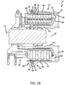
- FIG. 1B illustrates a cross-sectional view of a brake assembly, in accordance with various embodiments
- FIG. 2 is a schematic flow chart diagram of a method of manufacturing a ceramic matrix composite, in accordance with various embodiments.
- FIG. 3 is a schematic view of a ceramic matrix composite manufacturing system, in accordance with various embodiments.
- a manufacturing system(s) and associated method(s) for fabricating ceramic matrix composite components while mitigating the formation and accumulation of harmful/hazardous byproduct deposits While numerous details are included herein pertaining to aircraft components, such as brake components, the manufacturing system(s) and method(s) disclosed herein can be applied to fabricate other ceramic matrix composite components.
- an aircraft 10 may include landing gear such as left main landing gear 12 , right main landing gear 14 and nose landing gear 16 .
- Left main landing gear 12 , right main landing gear 14 , and nose landing gear 16 may generally support aircraft 10 when aircraft 10 is not flying, allowing aircraft 10 to taxi, take off and land without damage.
- Left main landing gear 12 may include wheel 13 A and wheel 13 B coupled by an axle 20 .
- Right main landing gear 14 may include wheel 15 A and wheel 15 B coupled by an axle 22 .
- Nose landing gear 16 may include nose wheel 17 A and nose wheel 17 B coupled by an axle 24 .
- aircraft 10 may comprise any number of landing gears and each landing gear may comprise any number of wheels.
- Left main landing gear 12 , right main landing gear 14 , and nose landing gear 16 may each be retracted for flight.
- the landing gear may extend from an underside 28 of the fuselage or from an underside of the wings 30 .
- Aircraft 10 may also include a brake system which may be applied to a wheel of a landing gear.
- the brake system of aircraft 10 may comprise a collection of units, assemblies, and subsystems that produce output signals for controlling the braking force and/or torque applied at each wheel (e.g., wheel 13 A, wheel 13 B, wheel 15 A, wheel 15 B, etc.).
- the brake system may communicate with the brakes of each landing gear (e.g., left main landing gear 12 , right main landing gear 14 , and/or nose landing gear 16 ), and each brake may be mounted to each wheel to apply and release braking force on one or more wheels.
- the brakes of an aircraft 10 may include a non-rotatable wheel support, a wheel (e.g., wheel 13 A, wheel 13 B, wheel 15 A, wheel 15 B, wheel 17 A, and/or wheel 17 B) mounted to the wheel support for rotation, and a brake disk stack.
- a wheel e.g., wheel 13 A, wheel 13 B, wheel 15 A, wheel 15 B, wheel 17 A, and/or wheel 17 B mounted to the wheel support for rotation
- a brake disk stack e.g., brake disk stack.
- brake assembly 110 may be found on an aircraft, in accordance with various embodiments.
- Brake assembly 110 may comprise a bogie axle 112 , a wheel 114 including a hub 116 and a wheel well 118 , a web 120 , a torque take-out assembly 122 , one or more torque bars 124 , a wheel rotational axis 126 , a wheel well recess 128 , an actuator 130 , multiple brake rotors 32 , multiple brake stators 34 , a pressure plate 36 , an end plate 38 , a heat shield 140 , multiple heat shield sections 142 , multiple heat shield carriers 144 , an air gap 146 , multiple torque bar bolts 148 , a torque bar pin 151 , a wheel web hole 152 , multiple heat shield fasteners 153 , multiple rotor lugs 154 , and multiple stator slots 156 .
- Brake disks e.g., interleaved rotors 32 and stators 34
- Rotors 32 are secured to torque bars 124 for rotation with wheel 114
- stators 34 are engaged with torque take-out assembly 122 .
- At least one actuator 130 is operable to compress interleaved rotors 32 and stators 34 for stopping the aircraft.
- actuator 130 is shown as a hydraulically actuated piston.
- Pressure plate 36 and end plate 38 are disposed at opposite ends of the interleaved rotors 32 and stators 34 .
- Torque take-out assembly 122 is secured to a stationary portion of the landing gear truck such as a bogie beam or other landing gear strut, such that torque take-out assembly 122 and stators 34 are prevented from rotating during braking of the aircraft.
- Rotors 32 and stators 34 may be fabricated from various materials, such as ceramic matrix composites. The brake disks may withstand and dissipate the heat generated from contact between the brake disks during braking.
- a method 200 of manufacturing a ceramic matrix composite component such as a brake disk
- the method 200 may include utilizing the manufacturing apparatus and manufacturing system 305 disclosed herein, as described in greater detail below with reference to FIG. 3 .
- the method 200 includes introducing a gaseous precursor into an inlet portion 312 of a chamber 310 at step 202 and introducing a gaseous mitigation agent into an outlet portion 313 of the chamber 310 at step 204 , according to various embodiments.
- One or more porous preforms 315 may be loaded into the inlet portion 312 of the chamber 310 , which may be a reactor furnace or other reaction compartment.
- the introduction of the gaseous precursor at step 202 results in densification of the porous preforms 315 and the introduction of the gaseous mitigation agent at step 204 shifts the reaction equilibrium to disfavor the formation of harmful and/or pyrophoric deposits, which can accumulate in the exhaust conduit 340 that is coupled in fluidic communication to the outlet portion of the chamber 310 , as described in greater detail below.
- the gaseous precursor may be introduced via a first inlet 320 into the inlet portion 312 of the chamber 310 and the gaseous mitigation agent may be introduced via a second inlet 330 into the outlet portion 313 of the chamber 310 .
- these two steps 202 , 204 are performed simultaneously to fabricate ceramic matrix composite components.
- both the gaseous precursor and the gaseous mitigation agent may be flowing into the respective portions 312 , 313 of the chamber 310 during fabrication.
- the inlet portion 312 of the chamber 310 is upstream of the outlet portion 313 of the chamber 310 .
- the gaseous precursor is introduced via the first inlet 320 at an inlet upstream side 311 of the inlet portion 312 of the chamber 310 and the gaseous mitigation agent is introduced via the second inlet 330 into an outlet upstream side 314 of the outlet portion 313 of the chamber 310 .
- the gaseous mitigation agent may not directly interact with the fibrous/porous preforms 315 and thus may not directly affect the reaction chemistry, as described below, in the inlet portion 312 of the chamber 310 .
- the gaseous mitigation agent generally conditions the effluent gas flowing from the inlet portion 312 to inhibit and/or mitigate the formation of harmful byproduct deposits in the exhaust piping (e.g., exhaust conduit 340 ), according to various embodiments.
- the respective flow rates of gaseous precursor and gaseous mitigation agent are different.
- Introducing the gaseous precursor at step 202 is performed at a first flow rate (e.g., a first molar flow rate) and introducing the gaseous mitigation agent at step 204 is performed at a second flow rate (e.g., a second molar flow rate).
- the second molar flow rate is between about 50% and about 300% higher than the gaseous precursor flow rate in the first stream.
- the second molar flow rate is between about 100% and about 200% higher than the gaseous precursor flow rate in the first stream.
- the method 200 includes controlling the temperature and pressure within pressurizing the chamber 310 to specific values.
- the method 200 may include heating the chamber 310 to above 1,000 degrees Celsius and may include maintaining the chamber 310 at 10 torr (1.33 kilopascal).
- the gaseous precursor includes, according to various embodiments, one or more reactants/reagents that react within the inlet portion 312 of the chamber 310 and infiltrate the pores of the porous preforms 315 to densify the porous preforms 315 .
- the gaseous precursor may include methyltrichlorosilane (MTS).
- MTS may dissociate in response to being introduced via the first inlet 320 into the inlet portion 312 of the chamber 310 and, via various intermediate reactions, may result in SiC deposits forming in the pores of the porous preforms 315 . Additional details pertaining to illustrative reactions that occur during the infiltration and deposition process are included below.
- the gaseous precursor stream may also include hydrogen gas, according to various embodiments.
- the MTS constitutes about 5% of the gaseous precursor stream.
- the gaseous mitigation agent is hydrogen gas.
- the reaction pathway that occurs within the chamber 310 includes the following reactions: CH 3 SiCl 3 ⁇ .SiCl 3 +.CH 3 Equation (1) .SiCl 3 +.CH 3 ⁇ SiC+3HCl Equation (2) .CH 3 +H 2 ⁇ CH 4 +.H Equation (3) .SiCl 3 +CH 3 SiCl 3 ⁇ HSiCl 3 +Cl 3 SiCH 2 .
- the gaseous mitigation agent introduced at step 204 of the method 200 interacts with the effluent from the inlet portion 312 of the chamber 310 (i.e., interacts with the gaseous stream exiting the inlet portion 312 after passing over and through the porous preforms 315 ).
- the gaseous mitigation agent shifts the reaction equilibrium of the above listed equations to disfavor the formation of harmful and/or pyrophoric deposits in the exhaust conduit 340 . That is, the gaseous mitigation agent alters the stoichiometric ratios of the various/intermediate reactions to mitigate the formation of harmful byproducts which can accumulate within the exhaust conduit 340 of the system 305 .
- the harmful byproduct deposits that conventionally form in the exhaust conduit are, for example, polychlorosilanes and cyclic carbosilanes that result from the free radicals and double bonded intermediate species produced in the equations above.
- the “extra” hydrogen gas introduced at step 204 into the outlet portion 313 of the chamber 310 may drive production of HCl via Equation (9), and which may shift the reaction equilibrium to disfavor the formation of the free radical and double bond intermediate species formed in Equations (5), (6), and (8).
- the gaseous precursor may be dimethyldichlorosilane or trimethylchlorosilane, among others.
- the gaseous mitigation agent may include water vapor, NH 3 gas, BCl 3 gas, or air, among others.
- the system 305 may include a first supply conduit 322 and a second supply conduit 323 .
- the first supply conduit 322 may deliver the gaseous precursor from a source to the inlet portion 312 of the chamber 310 via the first inlet 320 .
- the second supply conduit 323 may deliver the gaseous mitigation agent from a source to the outlet portion 313 of the chamber 310 via the second inlet 330 .
- a first valve 327 may be coupled to the first supply conduit 322 to control flow of the gaseous precursor and a second valve 328 may be coupled to the second supply conduit 323 to control flow of the gaseous mitigation agent.
- the system 305 may also include a purge valve 329 that is configured to control flow of a purge gas, through one or both of the first and second supply conduits 322 , 323 , into the chamber 310 for purging the chamber after a completed CVD process.
- a purge valve 329 that is configured to control flow of a purge gas, through one or both of the first and second supply conduits 322 , 323 , into the chamber 310 for purging the chamber after a completed CVD process.
- the second supply conduit 323 may extend into and through the inlet portion 312 of the chamber 310 to deliver the gaseous mitigation agent to the outlet portion 313 of the chamber 310 . That is, the second inlet 330 may be an outlet end of the second supply conduit 323 . In various embodiments, the second supply conduit 323 extends through the first inlet 320 . For example, the second supply conduit 323 may extend into the chamber 310 so as to deliver the gaseous mitigation agent to a central, upstream section of the outlet portion 313 of the chamber 310 . In various embodiments, the second inlet 330 is defined and disposed in a side wall of the chamber 310 .
- the inlet portion 312 of the chamber 310 of the manufacturing system 305 may include one or more retention spacers 316 for retaining one or of the porous preforms 315 .
- the retention spacers 316 may facilitate distributing the porous preforms 315 throughout the inlet portion 312 of the chamber 310 .
- the retention spacers 316 may be porous themselves, thus further allowing sufficient infiltration and deposition.
- the chamber 310 may include one or more gas distributors 318 that facilitate the mixing and distribution of the gaseous precursor flowing through the housed porous preforms 315 .
- the gas distributors 318 may also function to divide the inlet portion 312 into sub-compartments.
- the outlet portion 313 of the chamber 310 may define a gas mixing space 319 that may house a gas mixing substrate (e.g., a reaction sub-chamber).
- the gas mixing space 319 may facilitate mixing of the effluent gas from the inlet portion 312 with the gaseous mitigation agent introduced into the outlet portion 313 via the second inlet 330 .
- the gas mixing space 319 may include a porous substrate.
- the gas mixing space 319 may be loaded with a gas mixing substrate, such as volcanic rock or graphite, among other materials.
- any of the method or process descriptions may be executed in any order and are not necessarily limited to the order presented.
- any reference to singular includes plural embodiments, and any reference to more than one component or step may include a singular embodiment or step.
- Elements and steps in the figures are illustrated for simplicity and clarity and have not necessarily been rendered according to any particular sequence. For example, steps that may be performed concurrently or in different order are illustrated in the figures to help to improve understanding of embodiments of the present disclosure.
- Any reference to attached, fixed, connected or the like may include permanent, removable, temporary, partial, full and/or any other possible attachment option. Additionally, any reference to without contact (or similar phrases) may also include reduced contact or minimal contact. Surface shading lines may be used throughout the figures to denote different parts or areas but not necessarily to denote the same or different materials. In some cases, reference coordinates may be specific to each figure.
- references to “one embodiment,” “an embodiment,” “various embodiments,” etc. indicate that the embodiment described may include a particular feature, structure, or characteristic, but every embodiment may not necessarily include the particular feature, structure, or characteristic. Moreover, such phrases are not necessarily referring to the same embodiment. Further, when a particular feature, structure, or characteristic is described in connection with an embodiment, it is submitted that it is within the knowledge of one skilled in the art to affect such feature, structure, or characteristic in connection with other embodiments whether or not explicitly described. After reading the description, it will be apparent to one skilled in the relevant art(s) how to implement the disclosure in alternative embodiments.
Abstract
Description
CH3SiCl3→.SiCl3+.CH3 Equation (1)
.SiCl3+.CH3→SiC+3HCl Equation (2)
.CH3+H2→CH4+.H Equation (3)
.SiCl3+CH3SiCl3→HSiCl3+Cl3SiCH2. Equation (4)
CH3SiCl3→Cl2Si═CH2+HCl Equation (5)
HSiCl3→:SiCl2+HCl Equation (6)
CH3SiCl3→ClCH3+:SiCl2 Equation (7)
:SiCl2+CH4→:ClSiCH3+HCl Equation (8)
ClCH3+H2→CH4+HCl Equation (9)
Claims (9)
Priority Applications (3)
| Application Number | Priority Date | Filing Date | Title |
|---|---|---|---|
| US15/650,400 US10712005B2 (en) | 2017-07-14 | 2017-07-14 | Ceramic matrix composite manufacturing |
| EP18183737.8A EP3428310A1 (en) | 2017-07-14 | 2018-07-16 | Ceramic matrix composite manufacturing |
| US16/893,745 US11286209B2 (en) | 2017-07-14 | 2020-06-05 | Ceramic matrix composite manufacturing |
Applications Claiming Priority (1)
| Application Number | Priority Date | Filing Date | Title |
|---|---|---|---|
| US15/650,400 US10712005B2 (en) | 2017-07-14 | 2017-07-14 | Ceramic matrix composite manufacturing |
Related Child Applications (1)
| Application Number | Title | Priority Date | Filing Date |
|---|---|---|---|
| US16/893,745 Division US11286209B2 (en) | 2017-07-14 | 2020-06-05 | Ceramic matrix composite manufacturing |
Publications (2)
| Publication Number | Publication Date |
|---|---|
| US20190017704A1 US20190017704A1 (en) | 2019-01-17 |
| US10712005B2 true US10712005B2 (en) | 2020-07-14 |
Family
ID=63103758
Family Applications (2)
| Application Number | Title | Priority Date | Filing Date |
|---|---|---|---|
| US15/650,400 Active 2038-01-26 US10712005B2 (en) | 2017-07-14 | 2017-07-14 | Ceramic matrix composite manufacturing |
| US16/893,745 Active 2037-08-30 US11286209B2 (en) | 2017-07-14 | 2020-06-05 | Ceramic matrix composite manufacturing |
Family Applications After (1)
| Application Number | Title | Priority Date | Filing Date |
|---|---|---|---|
| US16/893,745 Active 2037-08-30 US11286209B2 (en) | 2017-07-14 | 2020-06-05 | Ceramic matrix composite manufacturing |
Country Status (2)
| Country | Link |
|---|---|
| US (2) | US10712005B2 (en) |
| EP (1) | EP3428310A1 (en) |
Citations (18)
| Publication number | Priority date | Publication date | Assignee | Title |
|---|---|---|---|---|
| US4340636A (en) * | 1980-07-30 | 1982-07-20 | Avco Corporation | Coated stoichiometric silicon carbide |
| JPH03257167A (en) | 1990-03-06 | 1991-11-15 | Hitachi Electron Eng Co Ltd | Reaction gas flow mechanism of atmospheric batch operated cvd device |
| US5527747A (en) | 1991-10-04 | 1996-06-18 | Georgia Tech Research Corporation | Rapid process for the preparation of diamond articles |
| US5609721A (en) | 1994-03-11 | 1997-03-11 | Fujitsu Limited | Semiconductor device manufacturing apparatus and its cleaning method |
| US5738908A (en) * | 1993-12-16 | 1998-04-14 | Societe Europeenne De Propulsion | Method of densifying porous substrates by chemical vapor infiltration of silicon carbide |
| US6197374B1 (en) | 1996-11-08 | 2001-03-06 | Sintec Keramik Gmbh & Co Kg | Method for chemical vapor infiltration of refractory substances, especially carbon and silicon carbide |
| US20020006478A1 (en) | 2000-07-12 | 2002-01-17 | Katsuhisa Yuda | Method of forming silicon oxide film and forming apparatus thereof |
| US6630029B2 (en) * | 2000-12-04 | 2003-10-07 | General Electric Company | Fiber coating method and reactor |
| US20040050328A1 (en) | 2002-09-17 | 2004-03-18 | Akira Kumagai | Film-forming system and film-forming method |
| US20050183666A1 (en) | 2004-02-20 | 2005-08-25 | Asm Japan K.K. | Shower plate having projections and plasma CVD apparatus using same |
| US20060060138A1 (en) | 2004-09-20 | 2006-03-23 | Applied Materials, Inc. | Diffuser gravity support |
| US20070272154A1 (en) | 2003-10-23 | 2007-11-29 | Manabu Amikura | Shower Head and Film-Forming Device Using the Same |
| US20110206585A1 (en) | 2008-08-09 | 2011-08-25 | Tokyo Electron Limited | Metal recovery method, metal recovery apparatus, gas exhaust system and film forming device using same |
| US20150353371A1 (en) | 2012-12-18 | 2015-12-10 | Invista North America S.A R.L. | Processes for producing hydrogen cyanide using static mixer |
| US20160225619A1 (en) * | 2015-02-02 | 2016-08-04 | Aixtron Se | Method and apparatus for deposition of a iii-v semiconductor layer |
| US20160229758A1 (en) * | 2015-02-11 | 2016-08-11 | United Technologies Corporation | Continuous chemical vapor deposition/infiltration coater |
| US20160297716A1 (en) | 2014-02-25 | 2016-10-13 | Ihi Corporation | Heat-resistant composite material production method and production device |
| US20160305015A1 (en) | 2014-02-17 | 2016-10-20 | Ihi Corporation | Heat-resistant composite material production method and production device |
Family Cites Families (7)
| Publication number | Priority date | Publication date | Assignee | Title |
|---|---|---|---|---|
| JPS5998295A (en) | 1982-11-27 | 1984-06-06 | 能美防災工業株式会社 | Alarm and controller for semiconductor plant or the like |
| FR2671797B1 (en) | 1991-01-18 | 1994-02-25 | Propulsion Ste Europeenne | METHOD FOR DENSIFICATION OF A POROUS SUBSTRATE BY A MATRIX CONTAINING CARBON. |
| GB0516695D0 (en) | 2005-08-15 | 2005-09-21 | Boc Group Plc | Microwave plasma reactor |
| KR100849929B1 (en) | 2006-09-16 | 2008-08-26 | 주식회사 피에조닉스 | Apparatus of chemical vapor deposition with a showerhead regulating the injection velocity of reactive gases positively and a method thereof |
| WO2010075467A1 (en) | 2008-12-23 | 2010-07-01 | Mks Instruments, Inc. | Reactive chemical containment system |
| JP2012069635A (en) * | 2010-09-22 | 2012-04-05 | Hitachi Kokusai Electric Inc | Deposition device, wafer holder and deposition method |
| US9852936B2 (en) * | 2015-01-29 | 2017-12-26 | Taiwan Semiconductor Manufacturing Co., Ltd. | Load port and method for loading and unloading cassette |
-
2017
- 2017-07-14 US US15/650,400 patent/US10712005B2/en active Active
-
2018
- 2018-07-16 EP EP18183737.8A patent/EP3428310A1/en active Pending
-
2020
- 2020-06-05 US US16/893,745 patent/US11286209B2/en active Active
Patent Citations (18)
| Publication number | Priority date | Publication date | Assignee | Title |
|---|---|---|---|---|
| US4340636A (en) * | 1980-07-30 | 1982-07-20 | Avco Corporation | Coated stoichiometric silicon carbide |
| JPH03257167A (en) | 1990-03-06 | 1991-11-15 | Hitachi Electron Eng Co Ltd | Reaction gas flow mechanism of atmospheric batch operated cvd device |
| US5527747A (en) | 1991-10-04 | 1996-06-18 | Georgia Tech Research Corporation | Rapid process for the preparation of diamond articles |
| US5738908A (en) * | 1993-12-16 | 1998-04-14 | Societe Europeenne De Propulsion | Method of densifying porous substrates by chemical vapor infiltration of silicon carbide |
| US5609721A (en) | 1994-03-11 | 1997-03-11 | Fujitsu Limited | Semiconductor device manufacturing apparatus and its cleaning method |
| US6197374B1 (en) | 1996-11-08 | 2001-03-06 | Sintec Keramik Gmbh & Co Kg | Method for chemical vapor infiltration of refractory substances, especially carbon and silicon carbide |
| US20020006478A1 (en) | 2000-07-12 | 2002-01-17 | Katsuhisa Yuda | Method of forming silicon oxide film and forming apparatus thereof |
| US6630029B2 (en) * | 2000-12-04 | 2003-10-07 | General Electric Company | Fiber coating method and reactor |
| US20040050328A1 (en) | 2002-09-17 | 2004-03-18 | Akira Kumagai | Film-forming system and film-forming method |
| US20070272154A1 (en) | 2003-10-23 | 2007-11-29 | Manabu Amikura | Shower Head and Film-Forming Device Using the Same |
| US20050183666A1 (en) | 2004-02-20 | 2005-08-25 | Asm Japan K.K. | Shower plate having projections and plasma CVD apparatus using same |
| US20060060138A1 (en) | 2004-09-20 | 2006-03-23 | Applied Materials, Inc. | Diffuser gravity support |
| US20110206585A1 (en) | 2008-08-09 | 2011-08-25 | Tokyo Electron Limited | Metal recovery method, metal recovery apparatus, gas exhaust system and film forming device using same |
| US20150353371A1 (en) | 2012-12-18 | 2015-12-10 | Invista North America S.A R.L. | Processes for producing hydrogen cyanide using static mixer |
| US20160305015A1 (en) | 2014-02-17 | 2016-10-20 | Ihi Corporation | Heat-resistant composite material production method and production device |
| US20160297716A1 (en) | 2014-02-25 | 2016-10-13 | Ihi Corporation | Heat-resistant composite material production method and production device |
| US20160225619A1 (en) * | 2015-02-02 | 2016-08-04 | Aixtron Se | Method and apparatus for deposition of a iii-v semiconductor layer |
| US20160229758A1 (en) * | 2015-02-11 | 2016-08-11 | United Technologies Corporation | Continuous chemical vapor deposition/infiltration coater |
Non-Patent Citations (14)
| Title |
|---|
| Application as filed U.S. Appl. No. 15/709,338, filed Sep. 18, 2017 and entitled "Gas Distribution for Chemical Vapor Deposition/Infiltration." |
| European Patent Office, European Search Report dated Aug. 21, 2019 in Application No. 18183737.8. |
| European Patent Office, European Search Report dated Dec. 13, 2018 in Application No. 18183737.8. |
| European Patent Office, European Search Report dated Feb. 19, 2019 18194913.2. |
| European Patent Office, European Search Report dated May 23, 2019 in Application No. 18194913.2. |
| J. Schlichting; Review 13 Chemical Vapor Deposition of Silicon Carbide*; Powder Metallurgy International vol. 12, No. 4, 1980, pp. 196-200. |
| J. Schlichting; Review 13 Chemical Vapor Deposition of Silicon Carbide; Powder Metallurgy International vol. 12, No. 3, 1980, pp. 141-147. |
| K. Brennfleck, et al.; In-situ-spectroscopic monitoring for SIC-CVD process control; Journal de Physique IV, 1999, pp. Pr8-1041-Pr8-1048. |
| USPTO, Advisory Action dated May 23, 2019 in U.S. Appl. No. 15/709,338. |
| USPTO, Final Office Action dated Mar. 14, 2019 in U.S. Appl. No. 15/709,338. |
| USPTO, Non-Final Office Action dated Dec. 13, 2018 in U.S. Appl. No. 15/709,338. |
| USPTO, Notice of Allowance dated Aug. 14, 2019 in U.S. Appl. No. 15/709,338. |
| USPTO, Restriction/Election Requirement dated Jul. 13, 2018 in U.S. Appl. No. 15/709,338. |
| Weigang G. Zhang and Klaus J. Huttinger; CVD of SiC from Methyltrichlorosinae. Part II: Compositionof the Gas Phase and the Deposit**; Chem. Vap. Deposition 2001, 7, No. 4, pp. 173-181. |
Also Published As
| Publication number | Publication date |
|---|---|
| US20200300470A1 (en) | 2020-09-24 |
| US11286209B2 (en) | 2022-03-29 |
| US20190017704A1 (en) | 2019-01-17 |
| EP3428310A1 (en) | 2019-01-16 |
Similar Documents
| Publication | Publication Date | Title |
|---|---|---|
| US11713281B2 (en) | Mitigating pyrophoric deposits during SiC CVI/CVD processes by introducing a mitigation agent into an exhaust conduit downstream of a reaction chamber | |
| EP3712122A1 (en) | Systems and methods for additively manufactured ceramic composites | |
| US11286209B2 (en) | Ceramic matrix composite manufacturing | |
| EP3228728B1 (en) | System and method for enhancing a diffusion limited cvi/cvd process | |
| US10975467B2 (en) | Gas distribution for chemical vapor deposition/infiltration | |
| EP3543222A1 (en) | Systems and methods for carbon structures incorporating silicon carbide | |
| Chawla et al. | Carbon fiber/carbon matrix composites | |
| US20210388876A1 (en) | Compliant interlayer | |
| EP1260729B1 (en) | Refractory-carbon composite brake friction elements | |
| EP3072864B1 (en) | Method of making a self-coating carbon/carbon composite member | |
| EP2933353B1 (en) | Method for producing fiber-reinforced composites | |
| EP3650424B1 (en) | Accelerated cvi densification of cmc through infiltration | |
| US20190389774A1 (en) | A method of chemical vapor infiltration or deposition | |
| WO2008075055A1 (en) | Method for forming a carbon-containing material for a brake disc | |
| EP3321243B1 (en) | Method of applying oxidation protection coating to carbon fibers | |
| EP3321244B1 (en) | Oxidation protection for carbon-carbon composites | |
| KR19990088072A (en) | A composite material of the carbon/carbon type having increased resistance to oxidation | |
| US20240051885A1 (en) | Hybrid high and low temperature coating | |
| US20230242451A1 (en) | Tools and methods for their formation and use | |
| US20230373868A1 (en) | Oxidation protection of composites |
Legal Events
| Date | Code | Title | Description |
|---|---|---|---|
| AS | Assignment |
Owner name: GOODRICH CORPORATION, NORTH CAROLINA Free format text: ASSIGNMENT OF ASSIGNORS INTEREST;ASSIGNORS:SHE, YING;DARDAS, ZISSIS A.;MENON, NAVEEN G.;AND OTHERS;SIGNING DATES FROM 20170713 TO 20170714;REEL/FRAME:043010/0272 |
|
| STPP | Information on status: patent application and granting procedure in general |
Free format text: DOCKETED NEW CASE - READY FOR EXAMINATION |
|
| STPP | Information on status: patent application and granting procedure in general |
Free format text: NON FINAL ACTION MAILED |
|
| STPP | Information on status: patent application and granting procedure in general |
Free format text: RESPONSE TO NON-FINAL OFFICE ACTION ENTERED AND FORWARDED TO EXAMINER |
|
| STPP | Information on status: patent application and granting procedure in general |
Free format text: PRE-INTERVIEW COMMUNICATION MAILED |
|
| STPP | Information on status: patent application and granting procedure in general |
Free format text: RESPONSE TO NON-FINAL OFFICE ACTION ENTERED AND FORWARDED TO EXAMINER |
|
| STPP | Information on status: patent application and granting procedure in general |
Free format text: FINAL REJECTION MAILED |
|
| STPP | Information on status: patent application and granting procedure in general |
Free format text: RESPONSE AFTER FINAL ACTION FORWARDED TO EXAMINER |
|
| STPP | Information on status: patent application and granting procedure in general |
Free format text: ADVISORY ACTION MAILED |
|
| STPP | Information on status: patent application and granting procedure in general |
Free format text: NOTICE OF ALLOWANCE MAILED -- APPLICATION RECEIVED IN OFFICE OF PUBLICATIONS |
|
| STPP | Information on status: patent application and granting procedure in general |
Free format text: PUBLICATIONS -- ISSUE FEE PAYMENT VERIFIED |
|
| STCF | Information on status: patent grant |
Free format text: PATENTED CASE |
|
| MAFP | Maintenance fee payment |
Free format text: PAYMENT OF MAINTENANCE FEE, 4TH YEAR, LARGE ENTITY (ORIGINAL EVENT CODE: M1551); ENTITY STATUS OF PATENT OWNER: LARGE ENTITY Year of fee payment: 4 |