US10710309B2 - Sonic label welding unit and method of manufacturing a multi-layered care label - Google Patents
Sonic label welding unit and method of manufacturing a multi-layered care label Download PDFInfo
- Publication number
- US10710309B2 US10710309B2 US15/492,370 US201715492370A US10710309B2 US 10710309 B2 US10710309 B2 US 10710309B2 US 201715492370 A US201715492370 A US 201715492370A US 10710309 B2 US10710309 B2 US 10710309B2
- Authority
- US
- United States
- Prior art keywords
- sonic
- label
- welding device
- labels
- welding
- Prior art date
- Legal status (The legal status is an assumption and is not a legal conclusion. Google has not performed a legal analysis and makes no representation as to the accuracy of the status listed.)
- Active, expires
Links
- 238000003466 welding Methods 0.000 title claims abstract description 115
- 238000004519 manufacturing process Methods 0.000 title abstract description 6
- 238000005520 cutting process Methods 0.000 claims description 12
- 239000000463 material Substances 0.000 description 39
- 238000000034 method Methods 0.000 description 11
- 238000009958 sewing Methods 0.000 description 11
- 230000008569 process Effects 0.000 description 8
- 239000004744 fabric Substances 0.000 description 6
- 239000004033 plastic Substances 0.000 description 4
- 229920003023 plastic Polymers 0.000 description 4
- 230000008859 change Effects 0.000 description 3
- 230000006870 function Effects 0.000 description 3
- 238000003825 pressing Methods 0.000 description 3
- 230000008901 benefit Effects 0.000 description 2
- 229920000139 polyethylene terephthalate Polymers 0.000 description 2
- 239000005020 polyethylene terephthalate Substances 0.000 description 2
- 238000005406 washing Methods 0.000 description 2
- 239000004677 Nylon Substances 0.000 description 1
- NIXOWILDQLNWCW-UHFFFAOYSA-N acrylic acid group Chemical group C(C=C)(=O)O NIXOWILDQLNWCW-UHFFFAOYSA-N 0.000 description 1
- 230000004075 alteration Effects 0.000 description 1
- 239000011248 coating agent Substances 0.000 description 1
- 238000000576 coating method Methods 0.000 description 1
- 238000001816 cooling Methods 0.000 description 1
- 230000003247 decreasing effect Effects 0.000 description 1
- 238000010586 diagram Methods 0.000 description 1
- 238000005108 dry cleaning Methods 0.000 description 1
- 239000000975 dye Substances 0.000 description 1
- 239000000835 fiber Substances 0.000 description 1
- 239000000155 melt Substances 0.000 description 1
- 238000012986 modification Methods 0.000 description 1
- 230000004048 modification Effects 0.000 description 1
- 229920001778 nylon Polymers 0.000 description 1
- 238000004806 packaging method and process Methods 0.000 description 1
- 229920000728 polyester Polymers 0.000 description 1
- -1 polyethylene terephthalate Polymers 0.000 description 1
- 230000008707 rearrangement Effects 0.000 description 1
- 230000003068 static effect Effects 0.000 description 1
- 239000000758 substrate Substances 0.000 description 1
- 239000012815 thermoplastic material Substances 0.000 description 1
- 238000013519 translation Methods 0.000 description 1
- 230000014616 translation Effects 0.000 description 1
- 238000013024 troubleshooting Methods 0.000 description 1
Images


Classifications
-
- B—PERFORMING OPERATIONS; TRANSPORTING
- B29—WORKING OF PLASTICS; WORKING OF SUBSTANCES IN A PLASTIC STATE IN GENERAL
- B29C—SHAPING OR JOINING OF PLASTICS; SHAPING OF MATERIAL IN A PLASTIC STATE, NOT OTHERWISE PROVIDED FOR; AFTER-TREATMENT OF THE SHAPED PRODUCTS, e.g. REPAIRING
- B29C65/00—Joining or sealing of preformed parts, e.g. welding of plastics materials; Apparatus therefor
- B29C65/02—Joining or sealing of preformed parts, e.g. welding of plastics materials; Apparatus therefor by heating, with or without pressure
- B29C65/08—Joining or sealing of preformed parts, e.g. welding of plastics materials; Apparatus therefor by heating, with or without pressure using ultrasonic vibrations
-
- B—PERFORMING OPERATIONS; TRANSPORTING
- B29—WORKING OF PLASTICS; WORKING OF SUBSTANCES IN A PLASTIC STATE IN GENERAL
- B29C—SHAPING OR JOINING OF PLASTICS; SHAPING OF MATERIAL IN A PLASTIC STATE, NOT OTHERWISE PROVIDED FOR; AFTER-TREATMENT OF THE SHAPED PRODUCTS, e.g. REPAIRING
- B29C65/00—Joining or sealing of preformed parts, e.g. welding of plastics materials; Apparatus therefor
- B29C65/74—Joining or sealing of preformed parts, e.g. welding of plastics materials; Apparatus therefor by welding and severing, or by joining and severing, the severing being performed in the area to be joined, next to the area to be joined, in the joint area or next to the joint area
- B29C65/745—Joining or sealing of preformed parts, e.g. welding of plastics materials; Apparatus therefor by welding and severing, or by joining and severing, the severing being performed in the area to be joined, next to the area to be joined, in the joint area or next to the joint area using a single unit having both a severing tool and a welding tool
- B29C65/7451—Joining or sealing of preformed parts, e.g. welding of plastics materials; Apparatus therefor by welding and severing, or by joining and severing, the severing being performed in the area to be joined, next to the area to be joined, in the joint area or next to the joint area using a single unit having both a severing tool and a welding tool the severing tool and the welding tool being movable with respect to one-another
-
- B—PERFORMING OPERATIONS; TRANSPORTING
- B29—WORKING OF PLASTICS; WORKING OF SUBSTANCES IN A PLASTIC STATE IN GENERAL
- B29C—SHAPING OR JOINING OF PLASTICS; SHAPING OF MATERIAL IN A PLASTIC STATE, NOT OTHERWISE PROVIDED FOR; AFTER-TREATMENT OF THE SHAPED PRODUCTS, e.g. REPAIRING
- B29C65/00—Joining or sealing of preformed parts, e.g. welding of plastics materials; Apparatus therefor
- B29C65/76—Making non-permanent or releasable joints
-
- B—PERFORMING OPERATIONS; TRANSPORTING
- B29—WORKING OF PLASTICS; WORKING OF SUBSTANCES IN A PLASTIC STATE IN GENERAL
- B29C—SHAPING OR JOINING OF PLASTICS; SHAPING OF MATERIAL IN A PLASTIC STATE, NOT OTHERWISE PROVIDED FOR; AFTER-TREATMENT OF THE SHAPED PRODUCTS, e.g. REPAIRING
- B29C66/00—General aspects of processes or apparatus for joining preformed parts
- B29C66/01—General aspects dealing with the joint area or with the area to be joined
- B29C66/05—Particular design of joint configurations
- B29C66/10—Particular design of joint configurations particular design of the joint cross-sections
- B29C66/11—Joint cross-sections comprising a single joint-segment, i.e. one of the parts to be joined comprising a single joint-segment in the joint cross-section
- B29C66/112—Single lapped joints
- B29C66/1122—Single lap to lap joints, i.e. overlap joints
-
- B—PERFORMING OPERATIONS; TRANSPORTING
- B29—WORKING OF PLASTICS; WORKING OF SUBSTANCES IN A PLASTIC STATE IN GENERAL
- B29C—SHAPING OR JOINING OF PLASTICS; SHAPING OF MATERIAL IN A PLASTIC STATE, NOT OTHERWISE PROVIDED FOR; AFTER-TREATMENT OF THE SHAPED PRODUCTS, e.g. REPAIRING
- B29C66/00—General aspects of processes or apparatus for joining preformed parts
- B29C66/01—General aspects dealing with the joint area or with the area to be joined
- B29C66/05—Particular design of joint configurations
- B29C66/306—Applying a mark during joining
- B29C66/3062—Applying a mark during joining in the form of letters or numbers
- B29C66/30621—Applying a mark during joining in the form of letters or numbers in the form of letters
-
- B—PERFORMING OPERATIONS; TRANSPORTING
- B29—WORKING OF PLASTICS; WORKING OF SUBSTANCES IN A PLASTIC STATE IN GENERAL
- B29C—SHAPING OR JOINING OF PLASTICS; SHAPING OF MATERIAL IN A PLASTIC STATE, NOT OTHERWISE PROVIDED FOR; AFTER-TREATMENT OF THE SHAPED PRODUCTS, e.g. REPAIRING
- B29C66/00—General aspects of processes or apparatus for joining preformed parts
- B29C66/40—General aspects of joining substantially flat articles, e.g. plates, sheets or web-like materials; Making flat seams in tubular or hollow articles; Joining single elements to substantially flat surfaces
- B29C66/41—Joining substantially flat articles ; Making flat seams in tubular or hollow articles
- B29C66/43—Joining a relatively small portion of the surface of said articles
-
- B—PERFORMING OPERATIONS; TRANSPORTING
- B29—WORKING OF PLASTICS; WORKING OF SUBSTANCES IN A PLASTIC STATE IN GENERAL
- B29C—SHAPING OR JOINING OF PLASTICS; SHAPING OF MATERIAL IN A PLASTIC STATE, NOT OTHERWISE PROVIDED FOR; AFTER-TREATMENT OF THE SHAPED PRODUCTS, e.g. REPAIRING
- B29C66/00—General aspects of processes or apparatus for joining preformed parts
- B29C66/40—General aspects of joining substantially flat articles, e.g. plates, sheets or web-like materials; Making flat seams in tubular or hollow articles; Joining single elements to substantially flat surfaces
- B29C66/41—Joining substantially flat articles ; Making flat seams in tubular or hollow articles
- B29C66/45—Joining of substantially the whole surface of the articles
-
- B—PERFORMING OPERATIONS; TRANSPORTING
- B29—WORKING OF PLASTICS; WORKING OF SUBSTANCES IN A PLASTIC STATE IN GENERAL
- B29C—SHAPING OR JOINING OF PLASTICS; SHAPING OF MATERIAL IN A PLASTIC STATE, NOT OTHERWISE PROVIDED FOR; AFTER-TREATMENT OF THE SHAPED PRODUCTS, e.g. REPAIRING
- B29C66/00—General aspects of processes or apparatus for joining preformed parts
- B29C66/70—General aspects of processes or apparatus for joining preformed parts characterised by the composition, physical properties or the structure of the material of the parts to be joined; Joining with non-plastics material
- B29C66/72—General aspects of processes or apparatus for joining preformed parts characterised by the composition, physical properties or the structure of the material of the parts to be joined; Joining with non-plastics material characterised by the structure of the material of the parts to be joined
- B29C66/729—Textile or other fibrous material made from plastics
-
- B—PERFORMING OPERATIONS; TRANSPORTING
- B29—WORKING OF PLASTICS; WORKING OF SUBSTANCES IN A PLASTIC STATE IN GENERAL
- B29C—SHAPING OR JOINING OF PLASTICS; SHAPING OF MATERIAL IN A PLASTIC STATE, NOT OTHERWISE PROVIDED FOR; AFTER-TREATMENT OF THE SHAPED PRODUCTS, e.g. REPAIRING
- B29C66/00—General aspects of processes or apparatus for joining preformed parts
- B29C66/70—General aspects of processes or apparatus for joining preformed parts characterised by the composition, physical properties or the structure of the material of the parts to be joined; Joining with non-plastics material
- B29C66/73—General aspects of processes or apparatus for joining preformed parts characterised by the composition, physical properties or the structure of the material of the parts to be joined; Joining with non-plastics material characterised by the intensive physical properties of the material of the parts to be joined, by the optical properties of the material of the parts to be joined, by the extensive physical properties of the parts to be joined, by the state of the material of the parts to be joined or by the material of the parts to be joined being a thermoplastic or a thermoset
- B29C66/739—General aspects of processes or apparatus for joining preformed parts characterised by the composition, physical properties or the structure of the material of the parts to be joined; Joining with non-plastics material characterised by the intensive physical properties of the material of the parts to be joined, by the optical properties of the material of the parts to be joined, by the extensive physical properties of the parts to be joined, by the state of the material of the parts to be joined or by the material of the parts to be joined being a thermoplastic or a thermoset characterised by the material of the parts to be joined being a thermoplastic or a thermoset
- B29C66/7392—General aspects of processes or apparatus for joining preformed parts characterised by the composition, physical properties or the structure of the material of the parts to be joined; Joining with non-plastics material characterised by the intensive physical properties of the material of the parts to be joined, by the optical properties of the material of the parts to be joined, by the extensive physical properties of the parts to be joined, by the state of the material of the parts to be joined or by the material of the parts to be joined being a thermoplastic or a thermoset characterised by the material of the parts to be joined being a thermoplastic or a thermoset characterised by the material of at least one of the parts being a thermoplastic
- B29C66/73921—General aspects of processes or apparatus for joining preformed parts characterised by the composition, physical properties or the structure of the material of the parts to be joined; Joining with non-plastics material characterised by the intensive physical properties of the material of the parts to be joined, by the optical properties of the material of the parts to be joined, by the extensive physical properties of the parts to be joined, by the state of the material of the parts to be joined or by the material of the parts to be joined being a thermoplastic or a thermoset characterised by the material of the parts to be joined being a thermoplastic or a thermoset characterised by the material of at least one of the parts being a thermoplastic characterised by the materials of both parts being thermoplastics
-
- B—PERFORMING OPERATIONS; TRANSPORTING
- B29—WORKING OF PLASTICS; WORKING OF SUBSTANCES IN A PLASTIC STATE IN GENERAL
- B29C—SHAPING OR JOINING OF PLASTICS; SHAPING OF MATERIAL IN A PLASTIC STATE, NOT OTHERWISE PROVIDED FOR; AFTER-TREATMENT OF THE SHAPED PRODUCTS, e.g. REPAIRING
- B29C66/00—General aspects of processes or apparatus for joining preformed parts
- B29C66/80—General aspects of machine operations or constructions and parts thereof
- B29C66/81—General aspects of the pressing elements, i.e. the elements applying pressure on the parts to be joined in the area to be joined, e.g. the welding jaws or clamps
- B29C66/814—General aspects of the pressing elements, i.e. the elements applying pressure on the parts to be joined in the area to be joined, e.g. the welding jaws or clamps characterised by the design of the pressing elements, e.g. of the welding jaws or clamps
- B29C66/8141—General aspects of the pressing elements, i.e. the elements applying pressure on the parts to be joined in the area to be joined, e.g. the welding jaws or clamps characterised by the design of the pressing elements, e.g. of the welding jaws or clamps characterised by the surface geometry of the part of the pressing elements, e.g. welding jaws or clamps, coming into contact with the parts to be joined
- B29C66/81433—General aspects of the pressing elements, i.e. the elements applying pressure on the parts to be joined in the area to be joined, e.g. the welding jaws or clamps characterised by the design of the pressing elements, e.g. of the welding jaws or clamps characterised by the surface geometry of the part of the pressing elements, e.g. welding jaws or clamps, coming into contact with the parts to be joined being toothed, i.e. comprising several teeth or pins, or being patterned
-
- B—PERFORMING OPERATIONS; TRANSPORTING
- B29—WORKING OF PLASTICS; WORKING OF SUBSTANCES IN A PLASTIC STATE IN GENERAL
- B29C—SHAPING OR JOINING OF PLASTICS; SHAPING OF MATERIAL IN A PLASTIC STATE, NOT OTHERWISE PROVIDED FOR; AFTER-TREATMENT OF THE SHAPED PRODUCTS, e.g. REPAIRING
- B29C66/00—General aspects of processes or apparatus for joining preformed parts
- B29C66/80—General aspects of machine operations or constructions and parts thereof
- B29C66/81—General aspects of the pressing elements, i.e. the elements applying pressure on the parts to be joined in the area to be joined, e.g. the welding jaws or clamps
- B29C66/816—General aspects of the pressing elements, i.e. the elements applying pressure on the parts to be joined in the area to be joined, e.g. the welding jaws or clamps characterised by the mounting of the pressing elements, e.g. of the welding jaws or clamps
- B29C66/8161—General aspects of the pressing elements, i.e. the elements applying pressure on the parts to be joined in the area to be joined, e.g. the welding jaws or clamps characterised by the mounting of the pressing elements, e.g. of the welding jaws or clamps said pressing elements being supported or backed-up by springs or by resilient material
-
- B—PERFORMING OPERATIONS; TRANSPORTING
- B29—WORKING OF PLASTICS; WORKING OF SUBSTANCES IN A PLASTIC STATE IN GENERAL
- B29C—SHAPING OR JOINING OF PLASTICS; SHAPING OF MATERIAL IN A PLASTIC STATE, NOT OTHERWISE PROVIDED FOR; AFTER-TREATMENT OF THE SHAPED PRODUCTS, e.g. REPAIRING
- B29C66/00—General aspects of processes or apparatus for joining preformed parts
- B29C66/80—General aspects of machine operations or constructions and parts thereof
- B29C66/82—Pressure application arrangements, e.g. transmission or actuating mechanisms for joining tools or clamps
- B29C66/824—Actuating mechanisms
- B29C66/8242—Pneumatic or hydraulic drives
-
- B—PERFORMING OPERATIONS; TRANSPORTING
- B29—WORKING OF PLASTICS; WORKING OF SUBSTANCES IN A PLASTIC STATE IN GENERAL
- B29C—SHAPING OR JOINING OF PLASTICS; SHAPING OF MATERIAL IN A PLASTIC STATE, NOT OTHERWISE PROVIDED FOR; AFTER-TREATMENT OF THE SHAPED PRODUCTS, e.g. REPAIRING
- B29C66/00—General aspects of processes or apparatus for joining preformed parts
- B29C66/80—General aspects of machine operations or constructions and parts thereof
- B29C66/83—General aspects of machine operations or constructions and parts thereof characterised by the movement of the joining or pressing tools
- B29C66/832—Reciprocating joining or pressing tools
- B29C66/8322—Joining or pressing tools reciprocating along one axis
-
- B—PERFORMING OPERATIONS; TRANSPORTING
- B29—WORKING OF PLASTICS; WORKING OF SUBSTANCES IN A PLASTIC STATE IN GENERAL
- B29C—SHAPING OR JOINING OF PLASTICS; SHAPING OF MATERIAL IN A PLASTIC STATE, NOT OTHERWISE PROVIDED FOR; AFTER-TREATMENT OF THE SHAPED PRODUCTS, e.g. REPAIRING
- B29C66/00—General aspects of processes or apparatus for joining preformed parts
- B29C66/90—Measuring or controlling the joining process
- B29C66/92—Measuring or controlling the joining process by measuring or controlling the pressure, the force, the mechanical power or the displacement of the joining tools
- B29C66/922—Measuring or controlling the joining process by measuring or controlling the pressure, the force, the mechanical power or the displacement of the joining tools by measuring the pressure, the force, the mechanical power or the displacement of the joining tools
- B29C66/9221—Measuring or controlling the joining process by measuring or controlling the pressure, the force, the mechanical power or the displacement of the joining tools by measuring the pressure, the force, the mechanical power or the displacement of the joining tools by measuring the pressure, the force or the mechanical power
-
- B—PERFORMING OPERATIONS; TRANSPORTING
- B29—WORKING OF PLASTICS; WORKING OF SUBSTANCES IN A PLASTIC STATE IN GENERAL
- B29C—SHAPING OR JOINING OF PLASTICS; SHAPING OF MATERIAL IN A PLASTIC STATE, NOT OTHERWISE PROVIDED FOR; AFTER-TREATMENT OF THE SHAPED PRODUCTS, e.g. REPAIRING
- B29C66/00—General aspects of processes or apparatus for joining preformed parts
- B29C66/90—Measuring or controlling the joining process
- B29C66/92—Measuring or controlling the joining process by measuring or controlling the pressure, the force, the mechanical power or the displacement of the joining tools
- B29C66/924—Measuring or controlling the joining process by measuring or controlling the pressure, the force, the mechanical power or the displacement of the joining tools by controlling or regulating the pressure, the force, the mechanical power or the displacement of the joining tools
- B29C66/9241—Measuring or controlling the joining process by measuring or controlling the pressure, the force, the mechanical power or the displacement of the joining tools by controlling or regulating the pressure, the force, the mechanical power or the displacement of the joining tools by controlling or regulating the pressure, the force or the mechanical power
-
- B—PERFORMING OPERATIONS; TRANSPORTING
- B29—WORKING OF PLASTICS; WORKING OF SUBSTANCES IN A PLASTIC STATE IN GENERAL
- B29C—SHAPING OR JOINING OF PLASTICS; SHAPING OF MATERIAL IN A PLASTIC STATE, NOT OTHERWISE PROVIDED FOR; AFTER-TREATMENT OF THE SHAPED PRODUCTS, e.g. REPAIRING
- B29C66/00—General aspects of processes or apparatus for joining preformed parts
- B29C66/90—Measuring or controlling the joining process
- B29C66/93—Measuring or controlling the joining process by measuring or controlling the speed
- B29C66/934—Measuring or controlling the joining process by measuring or controlling the speed by controlling or regulating the speed
-
- B—PERFORMING OPERATIONS; TRANSPORTING
- B29—WORKING OF PLASTICS; WORKING OF SUBSTANCES IN A PLASTIC STATE IN GENERAL
- B29C—SHAPING OR JOINING OF PLASTICS; SHAPING OF MATERIAL IN A PLASTIC STATE, NOT OTHERWISE PROVIDED FOR; AFTER-TREATMENT OF THE SHAPED PRODUCTS, e.g. REPAIRING
- B29C66/00—General aspects of processes or apparatus for joining preformed parts
- B29C66/90—Measuring or controlling the joining process
- B29C66/94—Measuring or controlling the joining process by measuring or controlling the time
- B29C66/944—Measuring or controlling the joining process by measuring or controlling the time by controlling or regulating the time
-
- B—PERFORMING OPERATIONS; TRANSPORTING
- B29—WORKING OF PLASTICS; WORKING OF SUBSTANCES IN A PLASTIC STATE IN GENERAL
- B29C—SHAPING OR JOINING OF PLASTICS; SHAPING OF MATERIAL IN A PLASTIC STATE, NOT OTHERWISE PROVIDED FOR; AFTER-TREATMENT OF THE SHAPED PRODUCTS, e.g. REPAIRING
- B29C66/00—General aspects of processes or apparatus for joining preformed parts
- B29C66/90—Measuring or controlling the joining process
- B29C66/96—Measuring or controlling the joining process characterised by the method for implementing the controlling of the joining process
- B29C66/967—Measuring or controlling the joining process characterised by the method for implementing the controlling of the joining process involving special data inputs or special data outputs, e.g. for monitoring purposes
- B29C66/9672—Measuring or controlling the joining process characterised by the method for implementing the controlling of the joining process involving special data inputs or special data outputs, e.g. for monitoring purposes involving special data inputs, e.g. involving barcodes, RFID tags
-
- B—PERFORMING OPERATIONS; TRANSPORTING
- B29—WORKING OF PLASTICS; WORKING OF SUBSTANCES IN A PLASTIC STATE IN GENERAL
- B29C—SHAPING OR JOINING OF PLASTICS; SHAPING OF MATERIAL IN A PLASTIC STATE, NOT OTHERWISE PROVIDED FOR; AFTER-TREATMENT OF THE SHAPED PRODUCTS, e.g. REPAIRING
- B29C66/00—General aspects of processes or apparatus for joining preformed parts
- B29C66/90—Measuring or controlling the joining process
- B29C66/96—Measuring or controlling the joining process characterised by the method for implementing the controlling of the joining process
- B29C66/967—Measuring or controlling the joining process characterised by the method for implementing the controlling of the joining process involving special data inputs or special data outputs, e.g. for monitoring purposes
- B29C66/9674—Measuring or controlling the joining process characterised by the method for implementing the controlling of the joining process involving special data inputs or special data outputs, e.g. for monitoring purposes involving special data outputs, e.g. special data display means
-
- B—PERFORMING OPERATIONS; TRANSPORTING
- B29—WORKING OF PLASTICS; WORKING OF SUBSTANCES IN A PLASTIC STATE IN GENERAL
- B29C—SHAPING OR JOINING OF PLASTICS; SHAPING OF MATERIAL IN A PLASTIC STATE, NOT OTHERWISE PROVIDED FOR; AFTER-TREATMENT OF THE SHAPED PRODUCTS, e.g. REPAIRING
- B29C66/00—General aspects of processes or apparatus for joining preformed parts
- B29C66/90—Measuring or controlling the joining process
- B29C66/98—Determining the joining area by using markings on at least one of the parts to be joined
-
- B—PERFORMING OPERATIONS; TRANSPORTING
- B29—WORKING OF PLASTICS; WORKING OF SUBSTANCES IN A PLASTIC STATE IN GENERAL
- B29C—SHAPING OR JOINING OF PLASTICS; SHAPING OF MATERIAL IN A PLASTIC STATE, NOT OTHERWISE PROVIDED FOR; AFTER-TREATMENT OF THE SHAPED PRODUCTS, e.g. REPAIRING
- B29C69/00—Combinations of shaping techniques not provided for in a single one of main groups B29C39/00 - B29C67/00, e.g. associations of moulding and joining techniques; Apparatus therefore
- B29C69/001—Combinations of shaping techniques not provided for in a single one of main groups B29C39/00 - B29C67/00, e.g. associations of moulding and joining techniques; Apparatus therefore a shaping technique combined with cutting, e.g. in parts or slices combined with rearranging and joining the cut parts
-
- B—PERFORMING OPERATIONS; TRANSPORTING
- B29—WORKING OF PLASTICS; WORKING OF SUBSTANCES IN A PLASTIC STATE IN GENERAL
- B29C—SHAPING OR JOINING OF PLASTICS; SHAPING OF MATERIAL IN A PLASTIC STATE, NOT OTHERWISE PROVIDED FOR; AFTER-TREATMENT OF THE SHAPED PRODUCTS, e.g. REPAIRING
- B29C2793/00—Shaping techniques involving a cutting or machining operation
- B29C2793/0081—Shaping techniques involving a cutting or machining operation before shaping
-
- B—PERFORMING OPERATIONS; TRANSPORTING
- B29—WORKING OF PLASTICS; WORKING OF SUBSTANCES IN A PLASTIC STATE IN GENERAL
- B29C—SHAPING OR JOINING OF PLASTICS; SHAPING OF MATERIAL IN A PLASTIC STATE, NOT OTHERWISE PROVIDED FOR; AFTER-TREATMENT OF THE SHAPED PRODUCTS, e.g. REPAIRING
- B29C2795/00—Printing on articles made from plastics or substances in a plastic state
- B29C2795/002—Printing on articles made from plastics or substances in a plastic state before shaping
-
- B—PERFORMING OPERATIONS; TRANSPORTING
- B29—WORKING OF PLASTICS; WORKING OF SUBSTANCES IN A PLASTIC STATE IN GENERAL
- B29C—SHAPING OR JOINING OF PLASTICS; SHAPING OF MATERIAL IN A PLASTIC STATE, NOT OTHERWISE PROVIDED FOR; AFTER-TREATMENT OF THE SHAPED PRODUCTS, e.g. REPAIRING
- B29C65/00—Joining or sealing of preformed parts, e.g. welding of plastics materials; Apparatus therefor
- B29C65/56—Joining or sealing of preformed parts, e.g. welding of plastics materials; Apparatus therefor using mechanical means or mechanical connections, e.g. form-fits
- B29C65/562—Joining or sealing of preformed parts, e.g. welding of plastics materials; Apparatus therefor using mechanical means or mechanical connections, e.g. form-fits using extra joining elements, i.e. which are not integral with the parts to be joined
-
- B—PERFORMING OPERATIONS; TRANSPORTING
- B29—WORKING OF PLASTICS; WORKING OF SUBSTANCES IN A PLASTIC STATE IN GENERAL
- B29C—SHAPING OR JOINING OF PLASTICS; SHAPING OF MATERIAL IN A PLASTIC STATE, NOT OTHERWISE PROVIDED FOR; AFTER-TREATMENT OF THE SHAPED PRODUCTS, e.g. REPAIRING
- B29C65/00—Joining or sealing of preformed parts, e.g. welding of plastics materials; Apparatus therefor
- B29C65/56—Joining or sealing of preformed parts, e.g. welding of plastics materials; Apparatus therefor using mechanical means or mechanical connections, e.g. form-fits
- B29C65/62—Stitching
-
- B—PERFORMING OPERATIONS; TRANSPORTING
- B29—WORKING OF PLASTICS; WORKING OF SUBSTANCES IN A PLASTIC STATE IN GENERAL
- B29C—SHAPING OR JOINING OF PLASTICS; SHAPING OF MATERIAL IN A PLASTIC STATE, NOT OTHERWISE PROVIDED FOR; AFTER-TREATMENT OF THE SHAPED PRODUCTS, e.g. REPAIRING
- B29C65/00—Joining or sealing of preformed parts, e.g. welding of plastics materials; Apparatus therefor
- B29C65/72—Joining or sealing of preformed parts, e.g. welding of plastics materials; Apparatus therefor by combined operations or combined techniques, e.g. welding and stitching
-
- B—PERFORMING OPERATIONS; TRANSPORTING
- B29—WORKING OF PLASTICS; WORKING OF SUBSTANCES IN A PLASTIC STATE IN GENERAL
- B29C—SHAPING OR JOINING OF PLASTICS; SHAPING OF MATERIAL IN A PLASTIC STATE, NOT OTHERWISE PROVIDED FOR; AFTER-TREATMENT OF THE SHAPED PRODUCTS, e.g. REPAIRING
- B29C66/00—General aspects of processes or apparatus for joining preformed parts
- B29C66/01—General aspects dealing with the joint area or with the area to be joined
- B29C66/05—Particular design of joint configurations
- B29C66/306—Applying a mark during joining
-
- B—PERFORMING OPERATIONS; TRANSPORTING
- B29—WORKING OF PLASTICS; WORKING OF SUBSTANCES IN A PLASTIC STATE IN GENERAL
- B29C—SHAPING OR JOINING OF PLASTICS; SHAPING OF MATERIAL IN A PLASTIC STATE, NOT OTHERWISE PROVIDED FOR; AFTER-TREATMENT OF THE SHAPED PRODUCTS, e.g. REPAIRING
- B29C66/00—General aspects of processes or apparatus for joining preformed parts
- B29C66/70—General aspects of processes or apparatus for joining preformed parts characterised by the composition, physical properties or the structure of the material of the parts to be joined; Joining with non-plastics material
- B29C66/71—General aspects of processes or apparatus for joining preformed parts characterised by the composition, physical properties or the structure of the material of the parts to be joined; Joining with non-plastics material characterised by the composition of the plastics material of the parts to be joined
-
- B—PERFORMING OPERATIONS; TRANSPORTING
- B29—WORKING OF PLASTICS; WORKING OF SUBSTANCES IN A PLASTIC STATE IN GENERAL
- B29C—SHAPING OR JOINING OF PLASTICS; SHAPING OF MATERIAL IN A PLASTIC STATE, NOT OTHERWISE PROVIDED FOR; AFTER-TREATMENT OF THE SHAPED PRODUCTS, e.g. REPAIRING
- B29C66/00—General aspects of processes or apparatus for joining preformed parts
- B29C66/70—General aspects of processes or apparatus for joining preformed parts characterised by the composition, physical properties or the structure of the material of the parts to be joined; Joining with non-plastics material
- B29C66/72—General aspects of processes or apparatus for joining preformed parts characterised by the composition, physical properties or the structure of the material of the parts to be joined; Joining with non-plastics material characterised by the structure of the material of the parts to be joined
- B29C66/729—Textile or other fibrous material made from plastics
- B29C66/7294—Non woven mats, e.g. felt
-
- B—PERFORMING OPERATIONS; TRANSPORTING
- B29—WORKING OF PLASTICS; WORKING OF SUBSTANCES IN A PLASTIC STATE IN GENERAL
- B29C—SHAPING OR JOINING OF PLASTICS; SHAPING OF MATERIAL IN A PLASTIC STATE, NOT OTHERWISE PROVIDED FOR; AFTER-TREATMENT OF THE SHAPED PRODUCTS, e.g. REPAIRING
- B29C66/00—General aspects of processes or apparatus for joining preformed parts
- B29C66/80—General aspects of machine operations or constructions and parts thereof
- B29C66/87—Auxiliary operations or devices
- B29C66/872—Starting or stopping procedures
-
- B—PERFORMING OPERATIONS; TRANSPORTING
- B29—WORKING OF PLASTICS; WORKING OF SUBSTANCES IN A PLASTIC STATE IN GENERAL
- B29C—SHAPING OR JOINING OF PLASTICS; SHAPING OF MATERIAL IN A PLASTIC STATE, NOT OTHERWISE PROVIDED FOR; AFTER-TREATMENT OF THE SHAPED PRODUCTS, e.g. REPAIRING
- B29C66/00—General aspects of processes or apparatus for joining preformed parts
- B29C66/90—Measuring or controlling the joining process
- B29C66/92—Measuring or controlling the joining process by measuring or controlling the pressure, the force, the mechanical power or the displacement of the joining tools
- B29C66/929—Measuring or controlling the joining process by measuring or controlling the pressure, the force, the mechanical power or the displacement of the joining tools characterized by specific pressure, force, mechanical power or displacement values or ranges
-
- B—PERFORMING OPERATIONS; TRANSPORTING
- B29—WORKING OF PLASTICS; WORKING OF SUBSTANCES IN A PLASTIC STATE IN GENERAL
- B29K—INDEXING SCHEME ASSOCIATED WITH SUBCLASSES B29B, B29C OR B29D, RELATING TO MOULDING MATERIALS OR TO MATERIALS FOR MOULDS, REINFORCEMENTS, FILLERS OR PREFORMED PARTS, e.g. INSERTS
- B29K2033/00—Use of polymers of unsaturated acids or derivatives thereof as moulding material
- B29K2033/04—Polymers of esters
-
- B—PERFORMING OPERATIONS; TRANSPORTING
- B29—WORKING OF PLASTICS; WORKING OF SUBSTANCES IN A PLASTIC STATE IN GENERAL
- B29K—INDEXING SCHEME ASSOCIATED WITH SUBCLASSES B29B, B29C OR B29D, RELATING TO MOULDING MATERIALS OR TO MATERIALS FOR MOULDS, REINFORCEMENTS, FILLERS OR PREFORMED PARTS, e.g. INSERTS
- B29K2067/00—Use of polyesters or derivatives thereof, as moulding material
- B29K2067/003—PET, i.e. poylethylene terephthalate
-
- B—PERFORMING OPERATIONS; TRANSPORTING
- B29—WORKING OF PLASTICS; WORKING OF SUBSTANCES IN A PLASTIC STATE IN GENERAL
- B29K—INDEXING SCHEME ASSOCIATED WITH SUBCLASSES B29B, B29C OR B29D, RELATING TO MOULDING MATERIALS OR TO MATERIALS FOR MOULDS, REINFORCEMENTS, FILLERS OR PREFORMED PARTS, e.g. INSERTS
- B29K2077/00—Use of PA, i.e. polyamides, e.g. polyesteramides or derivatives thereof, as moulding material
-
- B—PERFORMING OPERATIONS; TRANSPORTING
- B29—WORKING OF PLASTICS; WORKING OF SUBSTANCES IN A PLASTIC STATE IN GENERAL
- B29L—INDEXING SCHEME ASSOCIATED WITH SUBCLASS B29C, RELATING TO PARTICULAR ARTICLES
- B29L2031/00—Other particular articles
- B29L2031/48—Wearing apparel
-
- B—PERFORMING OPERATIONS; TRANSPORTING
- B29—WORKING OF PLASTICS; WORKING OF SUBSTANCES IN A PLASTIC STATE IN GENERAL
- B29L—INDEXING SCHEME ASSOCIATED WITH SUBCLASS B29C, RELATING TO PARTICULAR ARTICLES
- B29L2031/00—Other particular articles
- B29L2031/744—Labels, badges, e.g. marker sleeves
Definitions
- Product and other compliance labels play an important role in educating a user, such as a consumer, about a particular product and are well known in the art. Oftentimes it is necessary to attach multiple labels to a product, or include multiple labels within the product packaging. For example, sewing contractors, sewing operators, and other users typically sew multiple labels and other articles simultaneously into a garment so that the necessary labels are provided with a garment when sold to a consumer. However, it is difficult to keep the multiple labels or other articles aligned, which results in a decrease to their production capabilities, as the sewing operator has to align the individual units prior to affixing the labels to the garment. Additionally, multiple labels are difficult to handle at one time resulting in continuous adjustment and rearrangement of the position and alignment of the labels, and a decrease in sewing speed.
- the present invention discloses a sonic label welding unit that welds multiple labels together into one packet or stack with the individual labels aligned in the stack prior to bonding.
- the labels in the packet will be aligned and will be easier to handle for the sewing contractor or operator, and will increase sewing speed as well as the speed of garment production in the factory.
- the weld will hold the multiple labels together, 2 or more and preferably 4 or more, and keep the labels aligned during the sewing operation.
- the weld can be adjusted for strength such that the top and bottom label can be torn off without destroying the other labels.
- the welding unit will allow users to install a label packet into a garment without having to continuously adjust and rearrange the position and alignment of the labels.
- the present invention further discloses a method for manufacturing a multi-layered care label utilizing the sonic label welding unit described herein.
- the subject matter disclosed and claimed herein in one aspect thereof, comprises a sonic welding unit for welding multiple labels or other articles together using ultrasonic welding.
- the device may use a sonic horn or cold knife in connection with the provision of ultrasonic energy, especially when cutting coated materials.
- the device may also use a sonic or hot knife, especially when cutting uncoated materials.
- the sonic welding unit includes a digital controls main menu screen which has touch screen buttons that are utilized to go to specific screens.
- a user can press the registration button if using a registration mark on the product, the user can press the cut to length button if wanting to cut to a specific length, the user can press the printer screen button to use this screen while running product, and the user can press the timer button and enter a code to use manual functions, override the automatic features.
- the main menu screen also comprises, but is not limited to, controls such as start cycle, stop cycle, move registration number to the right or left by one index, or escape (go back a screen).
- the sonic welding device comprises an anvil and a textured or knurled head.
- the anvil is where the labels or other articles are placed on the welding device and allows the high frequency vibration from the welding device to be directed to the proper interfaces of the labels or other articles.
- the head allows the multiple labels or other articles to be assembled under pressure.
- the label welding device comprises a converter, a cold knife, sonic horn or sonotrode and a power supply to seal the multiple labels together via ultrasonic welding.
- the power supply delivers a high power AC signal with frequency matching the resonance frequency of the converter and sonic horn or cold knife.
- the converter converts the electrical signal into a mechanical vibration, and the sonic horn or cold knife applies the mechanical vibration to the labels to be welded.
- FIG. 1 illustrates a perspective view of a main menu touch screen for the sonic label welding device in accordance with the disclosed architecture
- FIG. 2 illustrates a perspective view of a printer screen touch screen for the sonic label welding device in accordance with the disclosed architecture
- FIG. 3 illustrates a perspective view of a cut to length screen touch screen for the sonic label welding device in accordance with the disclosed architecture
- FIG. 4 illustrates a perspective view of a registration screen touch screen for the sonic label welding device in accordance with the disclosed architecture
- FIG. 5A illustrates a perspective view of a manual sonic welding device in accordance with the disclosed architecture
- FIG. 5B illustrates a elevational view of the knurled or textured head of a sonic welding device with a trademark image thereon in accordance with the disclosed architecture
- FIG. 5C illustrates a perspective view of the image of the knurled or textured head of a sonic welding device with a trademark image thereon onto a multi-layer care label
- FIG. 6 illustrates a perspective view of the pressure settings of the sonic label welding device in accordance with the disclosed architecture
- FIG. 7A and FIG. 7B illustrate a perspective view of the cutting knife of the sonic label welding device in accordance with the disclosed architecture.
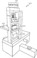
- FIG. 8 illustrates a perspective view of the welding station of the sonic label welding device in accordance with the disclosed architecture
- FIG. 9 illustrates a perspective view of the outfeed conveyor and hopper of the sonic label welding device in accordance with the disclosed architecture
- FIG. 10A and FIG. 10B illustrate a perspective view of the ultrasonic units of the sonic label welding device in accordance with the disclosed architecture
- FIG. 11A and FIG. 11B illustrate a perspective view of the ultrasonic air cooling of the sonic label welding device in accordance with the disclosed architecture
- FIG. 12 illustrates a perspective view of the sensors of the sonic label welding device in accordance with the disclosed architecture
- FIGS. 13-19 illustrate a perspective view of a stack of labels welded together via the sonic label welding device in accordance with the disclosed architecture
- FIGS. 20-26 illustrate a perspective view of the set up operations of the sonic label welding device in accordance with the disclosed architecture
- FIG. 27 illustrates the set-up process of the sonic label welding device in accordance with the disclosed architecture.
- the present invention discloses a sonic label welding device that welds multiple labels together into one packet or stack and a method for manufacturing a multi-layer care label using said sonic label welding device.
- the weld will hold the multiple labels together and keep the labels aligned during the sewing operation.
- the weld can be adjusted for strength such that the top and bottom label can be torn off without destroying the other labels.
- the labels Once the weld function is complete, the labels will be joined perfectly straight and aligned in a single packet, ready for the sew-in process.
- the sonic label welding unit comprises a digital controls main menu screen 100 which includes touch screen buttons that are utilized to go to specific screens. For example, a user can press the registration button 102 if using a registration mark on the product, the user can press the cut to length button 104 if wanting to cut to the label panels to a specific length, the user can press the printer screen button 106 to use this screen while running product, and the user can press the timers button 108 and enter a code to use manual functions.
- Main menu screen 100 also comprises, but is not limited to, controls such as a start cycle 110 , a stop cycle 112 , a move registration number to the left 114 or right 116 by one index, or escape 118 (to go back a screen).
- Printer screen 200 when printer screen button 106 is pressed, the printer screen 200 is activated which is typically used during normal runs.
- Printer screen 200 has multiple controls for controlling the run cycle of the welding unit. For example, but not limited to, a ‘reset weld’ button 202 which resets the weld count, a ‘label length’ button 204 which cuts the label to a desired length, a ‘speed’ button 206 which runs the cycle at a desired speed wherein the higher the number the faster the machine cycles, an ‘actual’ button 208 refers to the actual cycle speed, a ‘label weld count’ button 210 refers to the amount of labels that will be welded together, a ‘registration’ button 212 refers to the registration length, a ‘weld on’ button 214 that may be one color (e.g., red) when the unit is welding the labels together and a different color (e.g., blue) when the welding unit is shut off, a ‘main’ button 216 that sends the user back to main menu screen
- the cut to length screen 300 is activated which is used during set up when running a product to a desired length.
- the cut to length screen 300 has multiple controls for controlling the desired length of a product label.
- the ‘cut to length’ button refers to the current screen
- a ‘label length’ button 302 refers to the desired length of the label (i.e., cut to a certain length)
- an ‘actual’ button 304 refers to the actual cycle speed
- a ‘speed’ button 306 refers to the desired speed where the higher the number, the faster the unit cycles
- a ‘weld on’ button 308 that may be one color (e.g., red) when the unit is welding the labels together and a different color (e.g., blue) when the welding unit is shut off
- a ‘label weld count’ button 310 that refers to the amount of labels that will be welded together
- a ‘main’ button 312 that sends the user back to main menu screen 100
- a “registration” button 314 that send the user to a registration screen 400
- a plurality of buttons 316 that are used to change the values associated with the various buttons described above.
- Registration screen 400 when registration buttons 102 or 314 is pressed by the user, registration screen 400 is activated which is used during set up of the product.
- Registration screen 400 has multiple controls for using a registration mark on the product. For example, but not limited to, a ‘reset weld’ button 402 which resets the weld count, a ‘registration’ button which refers to the current screen, a ‘label length’ button 404 refers to the desired length of a label (i.e., cut to length), a ‘label weld count’ button 406 refers to the amount of labels welded together or cycles before the welding unit welds the labels together, a ‘registration length’ button 408 refers to the size of the label including the registration mark on a side of the label roll, a ‘weld on’ button 410 that may be one color (e.g., red) when the unit is welding the labels together and a different color (e.g., blue) when the welding unit is shut off, a ‘speed’ button
- FIG. 5A illustrates one embodiment of a sonic label welding device 500 for welding multiple labels or other articles together using ultrasonic welding.
- the sonic label welding device 500 comprises an anvil 502 and a head or press 504 .
- the anvil 502 is where the labels or other articles are placed on the welding device 500 and allows the high frequency vibration from the welding device 500 to be directed to the proper interfaces of the labels or other articles being joined.
- the head or press 504 of sonic welding device 500 allows the multiple labels or other articles to be assembled under pressure.
- the surface of head 504 is knurled or textured which influences the strength of the weld and helps to secure the labels or other articles in place on anvil 502 .
- pressure of the head 504 can be controlled pneumatically.
- a user can utilize an air cylinder 512 which will drive the head 504 downward against the labels.
- the air cylinder 512 is controlled by a solenoid valve (not shown) or any other suitable device as is known in the art.
- the welding device 500 has an input voltage to the solenoid valve of approximately between 100 to 120 Volts.
- the user can adjust the air pressure of the air cylinder 512 via an air pressure gauge (not shown) and other controls as is known in the art. Users can also adjust the pressure of the head 504 via manually adjusting a nut pressure control 516 , which influences the strength of the weld.
- the welding device 500 utilizes approximately 60 to 100 psi (pounds per square inch) input air pressure for air cylinder operation. Notwithstanding, it is contemplated that other known systems, such as hydraulic pressure systems, could also be used without affecting the overall concept of the present invention. Further detail on welding device 500 and its operation is included in U.S. Published Patent Application US2013/0122235 owned by Avery Dennison Corporation, which is hereby incorporated herein by reference.
- FIG. 5B illustrates a elevational view of the knurled or textured surface of head or press 504 of a sonic welding device with a trademark image 506 thereon in accordance with the disclosed architecture. Utilizing a trademark image on a label or any other sort of consumable good that can be utilized with the present invention, allows for indication of a supplier or source of the good.
- FIG. 5C illustrates a perspective view of the image 508 on a multi-layer care label 510 by the knurled or textured head or press 509 of a sonic welding device.
- the pressure setting controls the amount of pressure applied during the cutting or welding process;
- the depth setting controls how deep the head penetrates the material;
- the heat or energy setting controls how much heat or energy is applied (ultra-sonic supplies heat through vibration);
- the time setting controls the amount of time the heat and pressure are applied to the material.
- woven satin care labels it has been found that between 1.5 and 6 pounds of sonic weld force will result in a suitable weld that does not irritate the skin of the individual wearing a garment with the label attached thereto, and is soft enough to be easily penetrated by a sewing needle or plastic staple that is used to attached the care label to the garment.
- coated tape care labels it has been found that between 0.2 and 3 pounds of sonic weld force will result in a suitable weld that does not irritate the skin of the individual wearing a garment with the label attached thereto, and is soft enough to be easily penetrated by a sewing needle or plastic staple that is used to attached the care label to the garment.
- the sonic label welding unit also comprises a cutting knife or cold knife 700 with a guard, a stop adjustment, and an upper stroke limit.
- Cutting knife 700 is positioned after the nip roller and cycles down under air pressure. When cutting knife 700 reaches the bottom of its stroke, the ultrasonic horn (not shown) below the knife turns on and vibrates and generates the heat required to cut the label.
- a cold knife can be used with coated materials, for example with care labels, since the label may be next to the skin of a wearer, the coating can be applied to make the label smooth so it does not irritate the wearer of the garment.
- a hot or sonic knife can be used with uncoated materials without affecting the overall scope of the invention.
- a user can loosen the set screw on the stop adjustment 702 . More specifically, to increase the depth of the knife stroke, the user loosens or turns the stop adjustment 702 up; and to decrease the depth of the knife stroke, the user lowers or tightens the stop adjustment 702 . Thus, moving the stop adjustment 702 up means a deeper cut and lowering the stop adjustment will make a shallower cut.
- the welding station 800 comprises a welding cylinder 802 , a welding bar 804 , a hopper 806 , a gate 808 , and a gate cylinder 810 .
- the welding station 800 four pieces of label material (not shown) get staged in hopper 806 .
- welding bar 804 presses down on the label materials.
- the ultrasonic unit (not shown) turns on and welds the four pieces of label material together.
- the gate 808 then lowers and allows the stack of label materials to move to the outfeed conveyor (not shown). Then, gate 808 raises and starts the cycle again.
- an outfeed conveyor and hopper 900 comprise an exit conveyor 902 , an outfeed hopper 904 , and a back guide 906 .
- the stack of four labels are transported to the hopper by this conveyor. While the number of labels used in the present invention has been suggested to be four labels, it should be understood that more than four labels can be welded together and, likewise, fewer than four labels can be welded together without affecting the overall scope of the invention. Increasing or decreasing the number of labels to be secured or welded together will normally require an increase or decrease in the amount of pressure applied to the label stack, and adjustment of the other elements of the welding unit. Also, different types of materials may require different settings if, for example, the same number of labels are being secured in a set.
- the sonic welding device 500 also includes a converter (not shown), a sonic horn or sonotrode 518 and a power supply to seal the multiple labels together via ultrasonic welding.
- the converter and the sonic horn 518 are specifically tuned to resonate at the same ultrasonic frequency, such as approximately 20, 30, 35 or 40 kHz (kilohertz).
- the power supply or electronic ultrasonic generator delivers a high power AC signal with frequency matching the resonance frequency of the converter and sonic horn 518 .
- the converter converts the electrical signal into a mechanical vibration.
- the sonic horn 518 applies the high-frequency, mechanical vibrations to the labels to be welded.
- the sonic horn 518 operates perpendicular to the labels and fuses the labels together in the pattern of the stationary anvil 502 . Specifically, welding occurs as the result of heat generated at the interface between the surfaces of the labels.
- the ultrasonic energy melts the point of contact between the labels, which creates a bond or weld when cool. Welding times can vary, but typically the welds are formed in approximately between about 0.25 to about 0.5 seconds.
- the sonic horn 518 requires an input voltage of approximately between 207 to 253 Volts for ultrasonic power. Typically, the sonic horn 518 outputs approximately 36 kHz and approximately between 500 to 1200 Watts.
- the ultrasonic units 1000 comprise a horn connection 1010 , a pin connector 1020 , a test switch 1030 , and an amplitude adjustment 1040 .
- the two ultrasonic units are located under the machine, such that when you open the doors, they are visible.
- the pin connector 1020 of the ultrasonic units 1000 communicates with the PLC and the horn connection 1010 sends energy to the horn when called for.
- the ultrasonic units 1000 are powered via a power cord which provides voltage to the units.
- the test switch 1030 may be used to determine if the horn is working, and the amplitude adjustment 1040 may be used to increase or decrease the frequency. As shown in FIGS.
- the ultrasonic horns have to be cooled in order not to fail.
- a valve 1100 located in FIGS. 11A-11B supplies air to cool both of the horns. A user would open the valve 1100 for more air and close it for less.
- ultrasonic units 1000 further comprise sensors 1200 .
- the two sensors 1200 detect both the material and the registration mark.
- the mark may be placed on the material to allow the machine to accurately cut the label to its desired length. Both sensors should be lit and should be looking at the edges of the material.
- FIGS. 13-19 illustrate multiple labels 1300 welded together using the sonic welding device (shown in FIG. 5 ).
- the labels 1300 or other articles used with the sonic welding device are typically made of fabric (either woven or non-woven), thermoplastic material or a film-like material, such as acrylic, nylon, polyester, polyethylene terephthalate (PET), etc. which is essentially unreceptive to colored dyes.
- any other suitable material can be used as is known in the art for ultrasonic welding, without affecting the overall concept of the invention.
- the labels 1300 are utilized on a fabric garment, such as a shirt, shorts, pants, etc.
- the labels 1300 can be attached to substrates other than garments without affecting the overall concept of the invention.
- both sides of the labels 1300 can bear indicia, either printed or woven.
- indicia either printed or woven.
- each of the label plies may be provided with identical information but each label ply in a different language, e.g. English, Spanish, French, German, etc.
- Indicia may not only include text but also graphic symbols such as symbols designating the type of washing to be performed.
- Care labels 1300 can be of any size, but the typical dimensions of a care label are between 25-40 mm wide and 90-100 mm long. Care labels are typically constructed of a satin material, though other materials can also be used without affecting the overall concept of the present invention. Care labels 1300 typically include anywhere from two to six layers or panels, which are then sonically welded together to form a single multi-layer care label.
- the weld 1302 produced by the sonic welding device adheres the labels 1300 together, and can be adjusted for strength such that the top or bottom layers can be peeled or torn off without significantly damaging the labels below or above the label being removed.
- the labels 1300 are shown to be generally rectangular and to be separately releasably adhered together by the weld 1302 .
- the connection of the labels 1300 via the weld 1302 is preferably strong enough to keep the labels adhered together during repeated washings or dry cleanings, yet the weld is weak enough so that either one or multiple labels 1300 can be manually pulled or stripped away from the stack without destroying the other labels of the stack, or the garment or product bearing the labels.
- weld 1302 produced by the sonic welding device is preferably made perpendicular to the web travel, but generally parallel to the print appearing on the label. Nonetheless, it is also contemplated that weld 1302 could be made perpendicular to the print without affecting the overall concept of the present invention.
- Welds 1302 preferably run edge to edge of the label material (i.e., the width of the label material), though it is also contemplated that sonic welding device could be set up to “tack” weld in preselected areas (e.g., a spot weld at each edge of the label material, each edge and the center of the label material, center only, etc.) to suit user preference.
- the area of the multi-layered label containing the weld 1302 does not necessarily contain printed information therein, as this is typically where the label will be attached to the object or garment, but it may have printed information therein such as sewing instructions, brand information, security information, etc.
- the sonic weld process uses a combination of acoustic vibration and pressure to join the various labels together.
- the number of layers or labels being joined together will dictate the amount of pressure and weld time needed to successfully complete the sonic weld process.
- the more labels that are being joined the more pressure and/or weld time that is needed.
- the user would use less pressure and/or less weld time.
- tighter weaves or coated fabric labels will typically require more pressure and/or weld time than uncoated fabric labels.
- a user opens the nip roller clamp 2000 by lifting the arm 2002 , and winds the material 2004 (fabric, whether coated or uncoated, synthetic or natural fibers) back up on the old roll 2006 and removes the old roll 2006 from the holder.
- the user places a new label roll 2008 on the holder and adjusts the side guide by turning the adjustment knob 2010 , and threads through the unwind rollers 2012 , as shown in FIGS. 21A-21B .
- the user threads material 2004 up to the side guides and adjusts width of the guides to the material width using the adjustment knob 2014 shown in FIGS. 22A-22B .
- the user lifts the roller gate 2016 and opens the out-feed rollers after the material passes the knife and moves into the out-feed section.
- the user then closes the nip roller by pushing down on the lever and closes upper gate rollers 2018 until they touch the material 2004 .
- the user sets a length in the panel if using length only on the cutting, and also sets a stack count.
- the user uses the screen shown in FIGS. 24A-24B to cut the material 2004 to length, and sets the length by pressing the button 2020 and entering the number desired. If using registration marks, the user sets the panel to registration.
- the user uses the registration screen shown in FIGS. 24A-24B for registration marks, and sets the registration length by pressing the button 2022 and entering the value desired, and uses keys for incremental changes.
- the user sets the registration sensor if using registration marks 2024 , and sets the registration sensor to detect the registration mark 2024 on each side of the material 2004 .
- the user adjusts the welding hopper guide 2026 to the width of material 2004 , by loosening the four locking bolts 2028 , setting the width and then tightening the bolts 2028 .
- the user adjusts the exit hopper to the label width. The user sets the exit hopper by loosening the bolts shown and adjusting the width. Also, the user moves the back stop 2030 by placing it in a different hole. Then, the user starts device, tests the same and adjusts as necessary.
- the user would start the device, recheck set up, verify the material has correct dimensions, ensure cut is clean, ensure weld is good, adjust device speed to run consistently, and then run material.
- a web is fed into the cutter (i.e., a hot/sonic knife or a cold knife depending on the materials type as described more fully supra), the labels are cut, collected and assembled into a care label intermediate (i.e., a stack of pre-welded labels), sonically welded, collected and affixed to an object such as a garment.
- the care label is attached to a garment using plastic staples, such as Swiftach® plastic staples manufactured and sold by Avery Dennison Corporation.
- the web of labels can be preprinted or a printer can be installed inline just prior to the step of cutting the web into individual label panels.
- the printer is a SNAP® thermal printer manufactured and sold by Avery Dennison Corporation.
- An RFID inlay can also be added to the labels prior to the sonic welding of the same, or affixed to the label packet after welding.
- the user can run various trouble shooting options. For example, if the ultra-sonics of the unit are not functioning, the user may elect to test the generator. If more frequency or more air pressure is needed, the user should consider adjusting the knife depth and/or changing the knife. If the sonic label welding unit is not feeding properly, the user should check (i) to see if the web material is threaded incorrectly, (ii) if the nip roller is not down, (iii) if the nip roller needs replacement, and/or (iv) if the exit rollers are not pressing against the web material. If the sonic label welding unit jams, the user should check to see if both the welding hopper and the exit hopper are set correctly, and/or check to see if there is too much static or curl in the web material.
- FIG. 27 illustrates the set-up process of the sonic label welding device in accordance with the disclosed architecture. More specifically, at step 3000 , the user enters the welder setup and can elect to proceed to either the main menu 3010 or to make manual adjustments 3020 . If the user elects to proceed to the main menu 3010 , the user can then proceed to enter the desired settings or adjustments to one or more of the following: (i) registration 3012 ; (ii) cut to length 3014 ; (iii) printer screen 3016 ; and/or (iv) timers 3018 , each of which is described more fully supra.
- the user can then manually adjust one or more of the following: (i) pneumatic pressure 3022 ; (ii) cutting knife 3024 ; (iii) weld station 3026 ; (iv) ultrasonic box 3028 ; and/or (v) activate sensors 3029 .
- variable data made be included within the weld may include the source of consumable goods such as labels or the final destination or customer of the consumable goods.
- the variable data may also include, but is not limited to, a factory code of a specific vendor. This embodiment may be achieved by creating a chase or plate that has at least one patterned surface in which the RF horn presses against the chase or plate.
Landscapes
- Engineering & Computer Science (AREA)
- Mechanical Engineering (AREA)
- Physics & Mathematics (AREA)
- Fluid Mechanics (AREA)
- Textile Engineering (AREA)
- Labeling Devices (AREA)
- Lining Or Joining Of Plastics Or The Like (AREA)
- Making Paper Articles (AREA)
Abstract
Description
Claims (16)
Priority Applications (1)
| Application Number | Priority Date | Filing Date | Title |
|---|---|---|---|
| US15/492,370 US10710309B2 (en) | 2016-04-20 | 2017-04-20 | Sonic label welding unit and method of manufacturing a multi-layered care label |
Applications Claiming Priority (2)
| Application Number | Priority Date | Filing Date | Title |
|---|---|---|---|
| US201662325062P | 2016-04-20 | 2016-04-20 | |
| US15/492,370 US10710309B2 (en) | 2016-04-20 | 2017-04-20 | Sonic label welding unit and method of manufacturing a multi-layered care label |
Publications (2)
| Publication Number | Publication Date |
|---|---|
| US20170305068A1 US20170305068A1 (en) | 2017-10-26 |
| US10710309B2 true US10710309B2 (en) | 2020-07-14 |
Family
ID=58708004
Family Applications (1)
| Application Number | Title | Priority Date | Filing Date |
|---|---|---|---|
| US15/492,370 Active 2038-02-17 US10710309B2 (en) | 2016-04-20 | 2017-04-20 | Sonic label welding unit and method of manufacturing a multi-layered care label |
Country Status (5)
| Country | Link |
|---|---|
| US (1) | US10710309B2 (en) |
| EP (2) | EP3445563B1 (en) |
| CN (1) | CN109311236B (en) |
| BR (1) | BR112018071377A2 (en) |
| WO (1) | WO2017184833A1 (en) |
Families Citing this family (7)
| Publication number | Priority date | Publication date | Assignee | Title |
|---|---|---|---|---|
| CN113228053A (en) * | 2018-10-30 | 2021-08-06 | 艾利丹尼森零售信息服务有限公司 | Ultrasonic label welding system and method |
| US11443160B2 (en) | 2019-09-18 | 2022-09-13 | Sensormatic Electronics, LLC | Systems and methods for laser tuning and attaching RFID tags to products |
| US10970613B1 (en) | 2019-09-18 | 2021-04-06 | Sensormatic Electronics, LLC | Systems and methods for providing tags adapted to be incorporated with or in items |
| US11055588B2 (en) | 2019-11-27 | 2021-07-06 | Sensormatic Electronics, LLC | Flexible water-resistant sensor tag |
| US11755874B2 (en) | 2021-03-03 | 2023-09-12 | Sensormatic Electronics, LLC | Methods and systems for heat applied sensor tag |
| CN114055783A (en) * | 2021-12-02 | 2022-02-18 | 上海珂明注塑系统科技有限公司 | Ultrasonic welding process for injection molding |
| US11869324B2 (en) | 2021-12-23 | 2024-01-09 | Sensormatic Electronics, LLC | Securing a security tag into an article |
Citations (19)
| Publication number | Priority date | Publication date | Assignee | Title |
|---|---|---|---|---|
| US2752703A (en) | 1955-09-14 | 1956-07-03 | Edward F Halperin | Combination garment label |
| US3647599A (en) | 1969-06-16 | 1972-03-07 | Eastman Kodak Co | Ultrasonic film splicing apparatus |
| US3813021A (en) | 1972-11-06 | 1974-05-28 | Branson Instr | Electronic safety control circuit |
| EP0032703A1 (en) | 1980-01-17 | 1981-07-29 | Giuseppe Gorini | Apparatus for ultrasonically welding sheet materials |
| EP0043044A1 (en) | 1980-06-27 | 1982-01-06 | Otto Brand GmbH | Label and label manufacturing machine |
| US4313778A (en) | 1980-09-22 | 1982-02-02 | Branson Ultrasonics Corporation | Ultrasonic seaming apparatus |
| EP0081690A1 (en) | 1981-12-10 | 1983-06-22 | A. Mion S.P.A. Nastrificio | Method and apparatus for cutting woven labels |
| EP0786323A1 (en) | 1996-01-26 | 1997-07-30 | Emerson Electric Co. | Welding system and method of setting welding machine parameters |
| US6309490B1 (en) | 2000-05-10 | 2001-10-30 | Branson Ultrasonics Corporation | Air actuated ultrasonic tool |
| US20020176730A1 (en) | 2001-05-14 | 2002-11-28 | Frederick Bleckmann | Method and apparatus for production of labels |
| US20020183183A1 (en) | 2001-06-01 | 2002-12-05 | Turvey Robert R. | Method of and apparatus for producing plastic bags |
| JP2008156424A (en) | 2006-12-21 | 2008-07-10 | Shibaura Mechatronics Corp | Acf tape-sticking device, acf tape-pasting device and acf tape-sticking method |
| US20080263919A1 (en) | 2007-04-25 | 2008-10-30 | Halliday Brian L | Composite label and method of labeling |
| US7681378B2 (en) | 2005-12-08 | 2010-03-23 | Haver & Boecker Ohg | Method and apparatus for filling bags |
| US20110108184A1 (en) | 2009-11-09 | 2011-05-12 | Gm Global Technology Operations, Inc. | Active material-augmented vibration welding system and method of use |
| US8096339B2 (en) | 2008-03-27 | 2012-01-17 | Herrmann Ultraschalltechnik Gmbh & Co. Kg | Ultrasonic welding tool with fluid drive |
| JP3175127U (en) | 2012-02-10 | 2012-04-19 | 有限会社コスモシステム | Superposition care label and manufacturing apparatus thereof |
| US20130122235A1 (en) | 2011-11-15 | 2013-05-16 | Avery Dennison Corporation | Manual Sonic Welding Machine |
| US20150336272A1 (en) * | 2014-04-25 | 2015-11-26 | Gary Lee Drew | Machine for aligning items in a pattern and a method of use |
Family Cites Families (1)
| Publication number | Priority date | Publication date | Assignee | Title |
|---|---|---|---|---|
| JP3175127B2 (en) * | 1992-01-24 | 2001-06-11 | ニプロ株式会社 | Infusion container |
-
2017
- 2017-04-20 CN CN201780038000.2A patent/CN109311236B/en active Active
- 2017-04-20 BR BR112018071377A patent/BR112018071377A2/en not_active Application Discontinuation
- 2017-04-20 EP EP17723551.2A patent/EP3445563B1/en active Active
- 2017-04-20 US US15/492,370 patent/US10710309B2/en active Active
- 2017-04-20 EP EP19192293.9A patent/EP3587083B8/en active Active
- 2017-04-20 WO PCT/US2017/028557 patent/WO2017184833A1/en active Application Filing
Patent Citations (21)
| Publication number | Priority date | Publication date | Assignee | Title |
|---|---|---|---|---|
| US2752703A (en) | 1955-09-14 | 1956-07-03 | Edward F Halperin | Combination garment label |
| US3647599A (en) | 1969-06-16 | 1972-03-07 | Eastman Kodak Co | Ultrasonic film splicing apparatus |
| US3813021A (en) | 1972-11-06 | 1974-05-28 | Branson Instr | Electronic safety control circuit |
| FR2205762A1 (en) | 1972-11-06 | 1974-05-31 | Branson Instr | |
| EP0032703A1 (en) | 1980-01-17 | 1981-07-29 | Giuseppe Gorini | Apparatus for ultrasonically welding sheet materials |
| EP0043044A1 (en) | 1980-06-27 | 1982-01-06 | Otto Brand GmbH | Label and label manufacturing machine |
| US4313778A (en) | 1980-09-22 | 1982-02-02 | Branson Ultrasonics Corporation | Ultrasonic seaming apparatus |
| EP0081690A1 (en) | 1981-12-10 | 1983-06-22 | A. Mion S.P.A. Nastrificio | Method and apparatus for cutting woven labels |
| US4500372A (en) | 1981-12-10 | 1985-02-19 | A. Mion S.P.A. Nastrificio | Method and apparatus for cutting woven labels |
| EP0786323A1 (en) | 1996-01-26 | 1997-07-30 | Emerson Electric Co. | Welding system and method of setting welding machine parameters |
| US6309490B1 (en) | 2000-05-10 | 2001-10-30 | Branson Ultrasonics Corporation | Air actuated ultrasonic tool |
| US20020176730A1 (en) | 2001-05-14 | 2002-11-28 | Frederick Bleckmann | Method and apparatus for production of labels |
| US20020183183A1 (en) | 2001-06-01 | 2002-12-05 | Turvey Robert R. | Method of and apparatus for producing plastic bags |
| US7681378B2 (en) | 2005-12-08 | 2010-03-23 | Haver & Boecker Ohg | Method and apparatus for filling bags |
| JP2008156424A (en) | 2006-12-21 | 2008-07-10 | Shibaura Mechatronics Corp | Acf tape-sticking device, acf tape-pasting device and acf tape-sticking method |
| US20080263919A1 (en) | 2007-04-25 | 2008-10-30 | Halliday Brian L | Composite label and method of labeling |
| US8096339B2 (en) | 2008-03-27 | 2012-01-17 | Herrmann Ultraschalltechnik Gmbh & Co. Kg | Ultrasonic welding tool with fluid drive |
| US20110108184A1 (en) | 2009-11-09 | 2011-05-12 | Gm Global Technology Operations, Inc. | Active material-augmented vibration welding system and method of use |
| US20130122235A1 (en) | 2011-11-15 | 2013-05-16 | Avery Dennison Corporation | Manual Sonic Welding Machine |
| JP3175127U (en) | 2012-02-10 | 2012-04-19 | 有限会社コスモシステム | Superposition care label and manufacturing apparatus thereof |
| US20150336272A1 (en) * | 2014-04-25 | 2015-11-26 | Gary Lee Drew | Machine for aligning items in a pattern and a method of use |
Non-Patent Citations (1)
| Title |
|---|
| International Search Report and Written Opinion of ISA/EPO prepared for PCT/US17/28557 dated Jul. 21, 2017. |
Also Published As
| Publication number | Publication date |
|---|---|
| EP3445563A1 (en) | 2019-02-27 |
| EP3445563B1 (en) | 2023-10-04 |
| EP3587083B1 (en) | 2022-06-01 |
| EP3587083B8 (en) | 2022-08-10 |
| BR112018071377A2 (en) | 2019-02-05 |
| WO2017184833A1 (en) | 2017-10-26 |
| EP3587083A1 (en) | 2020-01-01 |
| US20170305068A1 (en) | 2017-10-26 |
| CN109311236A (en) | 2019-02-05 |
| CN109311236B (en) | 2022-05-10 |
Similar Documents
| Publication | Publication Date | Title |
|---|---|---|
| US10710309B2 (en) | Sonic label welding unit and method of manufacturing a multi-layered care label | |
| NO20053700L (en) | Process for bonding structural elements in paper machines and industrial fabrics to each other and to fabrics made in this way | |
| US20210009291A1 (en) | Cross seal devices for package forming systems and related methods | |
| US20030111184A1 (en) | Apparatus for transferring a discrete portion of first web onto a second web | |
| US20110083787A1 (en) | Method of impulse welding non-waterproof, digitally printable fabrics | |
| US5304266A (en) | Continuous loop ribbon welding system | |
| CN108883626A (en) | Laminating machine and for the method at least one coating | |
| JPH0356227A (en) | Adhering device for thermal adhesion film | |
| JP2018002284A (en) | Packaging bag and method for producing packaging bag | |
| US20040238098A1 (en) | Method and apparatus for production of RF labels | |
| JP2005529012A (en) | Device for bonding two packaging material webs | |
| US20120038088A1 (en) | Method and system for creating an apertured web-shaped material | |
| JP2006027814A (en) | Web joining method, web removing and joining method, and jointer | |
| US9902521B2 (en) | Manual sonic welding machine | |
| CN108890747A (en) | A kind of severing sensing device of cutting machine | |
| DE602005014223D1 (en) | Method for laying out and cutting limp sheet material | |
| KR101815221B1 (en) | Device for seamless join and seamline coating | |
| US6818084B2 (en) | Method and apparatus for bonding an additional layer of fabric to a label | |
| CN208841553U (en) | A kind of severing sensing device of cutting machine | |
| EP2439133B1 (en) | Method for manufacturing a membrane material | |
| EP1633921B1 (en) | Process for obtaining a fused seam for pieces of fabric | |
| KR200448660Y1 (en) | Return type machine for producing motif for use in accessoriessetting | |
| WO2005003432A1 (en) | Seaming apparatus | |
| Rödel | Ready-made technologies for fiber-reinforced plastic composites | |
| CN109878144A (en) | A kind of safety-type outer baffle type three tears the production technology of infusion bag |
Legal Events
| Date | Code | Title | Description |
|---|---|---|---|
| STPP | Information on status: patent application and granting procedure in general |
Free format text: NON FINAL ACTION MAILED |
|
| STPP | Information on status: patent application and granting procedure in general |
Free format text: RESPONSE TO NON-FINAL OFFICE ACTION ENTERED AND FORWARDED TO EXAMINER |
|
| STPP | Information on status: patent application and granting procedure in general |
Free format text: NON FINAL ACTION MAILED |
|
| STPP | Information on status: patent application and granting procedure in general |
Free format text: RESPONSE TO NON-FINAL OFFICE ACTION ENTERED AND FORWARDED TO EXAMINER |
|
| AS | Assignment |
Owner name: AVERY DENNISON RETAIL INFORMATION SERVICES, LLC, OHIO Free format text: ASSIGNMENT OF ASSIGNORS INTEREST;ASSIGNORS:CALDWELL, CHRISTOPHER T.;CHAMANDY, PAUL A.;HARRISON, DERRICK;SIGNING DATES FROM 20181119 TO 20200609;REEL/FRAME:052897/0441 |
|
| STPP | Information on status: patent application and granting procedure in general |
Free format text: PUBLICATIONS -- ISSUE FEE PAYMENT VERIFIED |
|
| STCF | Information on status: patent grant |
Free format text: PATENTED CASE |
|
| MAFP | Maintenance fee payment |
Free format text: PAYMENT OF MAINTENANCE FEE, 4TH YEAR, LARGE ENTITY (ORIGINAL EVENT CODE: M1551); ENTITY STATUS OF PATENT OWNER: LARGE ENTITY Year of fee payment: 4 |