US10698872B2 - Data collection management system, method, and recording medium encoded with a program for managing collection of data of plurality of machines - Google Patents
Data collection management system, method, and recording medium encoded with a program for managing collection of data of plurality of machines Download PDFInfo
- Publication number
- US10698872B2 US10698872B2 US15/922,075 US201815922075A US10698872B2 US 10698872 B2 US10698872 B2 US 10698872B2 US 201815922075 A US201815922075 A US 201815922075A US 10698872 B2 US10698872 B2 US 10698872B2
- Authority
- US
- United States
- Prior art keywords
- measurement
- machine tools
- data collection
- data
- setting
- Prior art date
- Legal status (The legal status is an assumption and is not a legal conclusion. Google has not performed a legal analysis and makes no representation as to the accuracy of the status listed.)
- Active
Links
Images


Classifications
-
- G—PHYSICS
- G06—COMPUTING OR CALCULATING; COUNTING
- G06F—ELECTRIC DIGITAL DATA PROCESSING
- G06F16/00—Information retrieval; Database structures therefor; File system structures therefor
- G06F16/20—Information retrieval; Database structures therefor; File system structures therefor of structured data, e.g. relational data
- G06F16/22—Indexing; Data structures therefor; Storage structures
- G06F16/221—Column-oriented storage; Management thereof
-
- G—PHYSICS
- G05—CONTROLLING; REGULATING
- G05B—CONTROL OR REGULATING SYSTEMS IN GENERAL; FUNCTIONAL ELEMENTS OF SUCH SYSTEMS; MONITORING OR TESTING ARRANGEMENTS FOR SUCH SYSTEMS OR ELEMENTS
- G05B19/00—Program-control systems
- G05B19/02—Program-control systems electric
- G05B19/18—Numerical control [NC], i.e. automatically operating machines, in particular machine tools, e.g. in a manufacturing environment, so as to execute positioning, movement or co-ordinated operations by means of program data in numerical form
- G05B19/408—Numerical control [NC], i.e. automatically operating machines, in particular machine tools, e.g. in a manufacturing environment, so as to execute positioning, movement or co-ordinated operations by means of program data in numerical form characterised by data handling or data format, e.g. reading, buffering or conversion of data
-
- G—PHYSICS
- G05—CONTROLLING; REGULATING
- G05B—CONTROL OR REGULATING SYSTEMS IN GENERAL; FUNCTIONAL ELEMENTS OF SUCH SYSTEMS; MONITORING OR TESTING ARRANGEMENTS FOR SUCH SYSTEMS OR ELEMENTS
- G05B19/00—Program-control systems
- G05B19/02—Program-control systems electric
- G05B19/418—Total factory control, i.e. centrally controlling a plurality of machines, e.g. direct or distributed numerical control [DNC], flexible manufacturing systems [FMS], integrated manufacturing systems [IMS] or computer integrated manufacturing [CIM]
- G05B19/4183—Total factory control, i.e. centrally controlling a plurality of machines, e.g. direct or distributed numerical control [DNC], flexible manufacturing systems [FMS], integrated manufacturing systems [IMS] or computer integrated manufacturing [CIM] characterised by data acquisition, e.g. workpiece identification
-
- G—PHYSICS
- G06—COMPUTING OR CALCULATING; COUNTING
- G06F—ELECTRIC DIGITAL DATA PROCESSING
- G06F16/00—Information retrieval; Database structures therefor; File system structures therefor
- G06F16/20—Information retrieval; Database structures therefor; File system structures therefor of structured data, e.g. relational data
- G06F16/22—Indexing; Data structures therefor; Storage structures
- G06F16/2282—Tablespace storage structures; Management thereof
-
- G—PHYSICS
- G05—CONTROLLING; REGULATING
- G05B—CONTROL OR REGULATING SYSTEMS IN GENERAL; FUNCTIONAL ELEMENTS OF SUCH SYSTEMS; MONITORING OR TESTING ARRANGEMENTS FOR SUCH SYSTEMS OR ELEMENTS
- G05B19/00—Program-control systems
- G05B19/02—Program-control systems electric
- G05B19/18—Numerical control [NC], i.e. automatically operating machines, in particular machine tools, e.g. in a manufacturing environment, so as to execute positioning, movement or co-ordinated operations by means of program data in numerical form
- G05B19/4093—Numerical control [NC], i.e. automatically operating machines, in particular machine tools, e.g. in a manufacturing environment, so as to execute positioning, movement or co-ordinated operations by means of program data in numerical form characterised by part programming, e.g. entry of geometrical information as taken from a technical drawing, combining this with machining and material information to obtain control information, named part program, for the NC machine
- G05B19/40937—Numerical control [NC], i.e. automatically operating machines, in particular machine tools, e.g. in a manufacturing environment, so as to execute positioning, movement or co-ordinated operations by means of program data in numerical form characterised by part programming, e.g. entry of geometrical information as taken from a technical drawing, combining this with machining and material information to obtain control information, named part program, for the NC machine concerning programming of machining or material parameters, pocket machining
- G05B19/40938—Tool management
-
- G—PHYSICS
- G05—CONTROLLING; REGULATING
- G05B—CONTROL OR REGULATING SYSTEMS IN GENERAL; FUNCTIONAL ELEMENTS OF SUCH SYSTEMS; MONITORING OR TESTING ARRANGEMENTS FOR SUCH SYSTEMS OR ELEMENTS
- G05B2219/00—Program-control systems
- G05B2219/30—Nc systems
- G05B2219/31—From computer integrated manufacturing till monitoring
- G05B2219/31288—Archive collected data into history file
-
- Y—GENERAL TAGGING OF NEW TECHNOLOGICAL DEVELOPMENTS; GENERAL TAGGING OF CROSS-SECTIONAL TECHNOLOGIES SPANNING OVER SEVERAL SECTIONS OF THE IPC; TECHNICAL SUBJECTS COVERED BY FORMER USPC CROSS-REFERENCE ART COLLECTIONS [XRACs] AND DIGESTS
- Y02—TECHNOLOGIES OR APPLICATIONS FOR MITIGATION OR ADAPTATION AGAINST CLIMATE CHANGE
- Y02P—CLIMATE CHANGE MITIGATION TECHNOLOGIES IN THE PRODUCTION OR PROCESSING OF GOODS
- Y02P90/00—Enabling technologies with a potential contribution to greenhouse gas [GHG] emissions mitigation
- Y02P90/02—Total factory control, e.g. smart factories, flexible manufacturing systems [FMS] or integrated manufacturing systems [IMS]
-
- Y—GENERAL TAGGING OF NEW TECHNOLOGICAL DEVELOPMENTS; GENERAL TAGGING OF CROSS-SECTIONAL TECHNOLOGIES SPANNING OVER SEVERAL SECTIONS OF THE IPC; TECHNICAL SUBJECTS COVERED BY FORMER USPC CROSS-REFERENCE ART COLLECTIONS [XRACs] AND DIGESTS
- Y02—TECHNOLOGIES OR APPLICATIONS FOR MITIGATION OR ADAPTATION AGAINST CLIMATE CHANGE
- Y02P—CLIMATE CHANGE MITIGATION TECHNOLOGIES IN THE PRODUCTION OR PROCESSING OF GOODS
- Y02P90/00—Enabling technologies with a potential contribution to greenhouse gas [GHG] emissions mitigation
- Y02P90/30—Computing systems specially adapted for manufacturing
Definitions
- the present invention relates to a data collection management system, method, and recording medium encoded with a program for managing collection of data of a plurality of machines.
- a system that manages a plurality of machines using one management device is known.
- a monitoring system disclosed in Patent Document 1 a plurality of data collection PCs are connected to a plurality of semiconductor manufacturing apparatuses in one-to-one correspondence.
- Each data collection PC collects processing state data of each semiconductor manufacturing apparatus.
- one monitoring PC monitors the processing state data collected by the plurality of data collection PCs.
- Patent Document describes that information (an IP address or the like) on the data collection PC and monitoring items (temperature and the like) of the semiconductor manufacturing apparatus are registered in the monitoring PC.
- Patent Document 1 makes no description relating to the monitoring PC performing setting of a monitoring target machine, such as setting of monitoring items.
- a monitoring target machine such as setting of monitoring items.
- it may be necessary to set a measurement item or the like serving as a data collection target for respective machines.
- An object of the present invention is to alleviate the work load of managing a plurality of machines more appropriately.
- a data collection management system (for example, a data collection management system 1 to be described later) of the present invention is
- a data collection management system including a data collection management device (for example, a data collection management device 10 to be described later) that manages acquisition of measurement data of a plurality of machine tools (for example, a machine tool 20 to be described later), wherein the data collection management device includes: a setting storage unit (for example, a storage unit 16 to be described later) that stores connection settings with the plurality of machine tools and setting of types of measurement data measured in each of the machine tools; a setting unit (for example, a setting management unit 11 b to be described later) that sets the connection settings and the types of the measurement data to a measurement tool corresponding to each of the machine tools; and an execution management unit (for example, a measurement tool execution management unit 11 c to be described later) that executes measurement of each of the machine tools using the measurement tool according to the settings performed by the setting unit.
- a setting storage unit for example, a storage unit 16 to be described later
- a setting unit for example, a setting management unit 11 b to be described later
- an execution management unit for
- the data collection management device may include:
- a measurement data acquisition unit (for example, a measurement tool execution management unit lic to be described later) that acquires the measurement data on the machine tool.
- the data collection management device may include the measurement tool corresponding to each of the machine tools.
- the data collection management system according to (1) or (2) may further include an information processing device (for example, information processing devices 10 - 1 to 10 - n to be described later) that manages acquisition of the measurement data on one or some of the machine tools among the plurality of machine tools, and the information processing device may include the measurement tool corresponding to one or some of the machine tools among the plurality of machine tools.
- an information processing device for example, information processing devices 10 - 1 to 10 - n to be described later
- the information processing device may include the measurement tool corresponding to one or some of the machine tools among the plurality of machine tools.
- the data collection management device may include:
- a display control unit (for example, a UI display control unit 11 a to be described later) that displays an interface screen for controlling the setting unit performing the connection settings and the setting of the types of the measurement data to the measurement tool and controlling the measurement tool executing measurement on the respective machine tools
- the display control unit may display the machine tools serving as measurement targets on the interface screen as a list, and when an item of the machine tools displayed as the list is selected, processes related to setting on the measurement tool corresponding to the machine tool, connection by communication with the machine tool, or measurement on the machine tool may be executed.
- the display control unit may receive addition and deletion of the machine tool serving as the measurement target on the interface screen.
- a data collection management method of the present invention is
- a data collection management method executed in a data collection management system including a data collection management device that manages acquisition of measurement data of a plurality of machine tools, wherein
- the data collection management device executes:
- a program of the present invention is a program for causing a computer that forms a data collection management device that manages acquisition of measurement data on a plurality of machine tools to realize:
- FIG. 1 is a schematic diagram illustrating a system configuration of a data collection management system according to an embodiment of the present invention.
- FIG. 2 is a block diagram illustrating a configuration of a data collection management device.
- FIG. 3 is a schematic diagram illustrating an example of a connection management screen.
- FIG. 4 is a schematic diagram illustrating an example of a connection setting screen.
- FIG. 5A is a schematic diagram illustrating an example of a connection status display screen.
- FIG. 5B is a schematic diagram illustrating an example of a connection status display screen.
- FIG. 5C is a schematic diagram illustrating an example of a connection status display screen.
- FIG. 6 is a flowchart illustrating the flow of an integrated management process executed by a data collection management device.
- FIG. 7 is a schematic diagram illustrating a system configuration of a data collection management system in which a measurement tool and a measurement tool execution management unit are provided in different information processing devices.
- FIG. 8 is a schematic diagram illustrating a system configuration of a data collection management system in which a measurement data save file is stored in a storage device on a network.
- FIG. 1 is a schematic diagram illustrating a system configuration of a data collection management system 1 according to an embodiment of the present invention.
- the data collection management system 1 includes a data collection management device 10 and a plurality of machine tools 20 - 1 to 20 - n (n is an integer of 2 or more).
- the data collection management device 10 and the plurality of machine tools 20 - 1 to 20 - n can communicate with each other via a network 30 such as a cable or wireless LAN.
- the data collection management device 10 and the plurality of machine tools 20 - 1 to 20 - n may be connected by a communication cable such as a universal serial bus (USB) cable.
- USB universal serial bus
- the plurality of machine tools 20 - 1 to 20 - n will be referred to simply as a machine tool 20 when they are not distinguished from each other.
- the data collection management device 10 is configured as an information processing device such as a personal computer (PC) or a server device.
- the data collection management device 10 includes measurement tools so as to correspond to the machine tools 20 - 1 to 20 - n , the measurement tools executing setting of connection to each of the machine tools 20 - 1 to 20 - n , setting of the content of measurement data (the types of measurement data, a measurement method, and the like), and collection of the measurement data.
- the measurement tool is installed in the data collection management device 10 as an application program.
- the data collection management device 10 has an integrated management function of managing the respective measurement tools corresponding to the machine tools 20 - 1 to 20 - n in an integrated manner.
- the data collection management device 10 manages setting of connection to the plurality of measurement tools, setting of the content of measurement data (the types of measurement data, a measurement method, and the like), collection of the measurement data, saving of various settings, and saving of the measurement data in a centralized manner.
- the machine tool 20 is configured as a numerically controlled (NC) machine tool or an industrial robot installed in a manufacturing line or the like.
- each of the machine tools 20 - 1 to 20 - n includes a spindle motor and a servomotor and acquires the position of a machine moving part (a servo shaft) driven by the servomotor and the position of a main shaft (a spindle shaft) driven by the spindle motor as one piece of measurement data.
- FIG. 2 is a block diagram illustrating a configuration of the data collection management device 10 .
- the data collection management device 10 includes a central processing unit (CPU) 11 , a ROM 12 , a RAM 13 , an input unit 14 , a display unit 15 , a storage unit 16 , and a communication unit 17 .
- CPU central processing unit
- ROM 12 read-only memory
- RAM 13 random access memory
- the CPU 11 controls the entire data collection management device 10 by executing various programs stored in the storage unit 16 .
- the CPU 11 executes a program for a process of managing the plurality of measurement tools in an integrated manner (hereinafter, this process will be referred to as an “integrated management process”).
- a program for the integrated management process is executed, a UI display control unit 11 a , a setting management unit 11 b , and a measurement tool execution management unit 11 c are formed in the CPU 11 as functional configuration units.
- the UI display control unit 11 a displays various display screens such as a menu screen, a setting screen, and a status display screen of the integrated management process. Moreover, the UI display control unit 11 a receives the input of a user's operation on various display screens.
- the setting management unit 11 b performs various settings of individual measurement tools, such as setting of connection of the machine tool 20 to the measurement tool and setting of the content of measurement data (the types of measurement data, a measurement method, and the like) according to the user's input.
- Various settings of individual measurement tools are stored in a measurement setting file.
- a position control command value from a programmable machine controller (PMC) a sensor detection value, the number of pieces of measurement data, a sampling period, and the like are set with regard to the servo shaft and the spindle shaft.
- signals associated with serial communications for connecting the PMC and various I/Os may be used as a measurement target.
- the sampling period is set for the position control command value and the sensor detection value or is set for the individual serial communication signals.
- the setting management unit 11 b performs various settings for the integrated management process, such as selection of the machine tools 20 serving as a management target of the integrated management process and management of a file serving as a setting save destination.
- Various settings for the integrated management process are stored in a management file. Detailed content of various settings for the integrated management process will be described later.
- the measurement tool execution management unit 11 c activates a measurement tool for the machine tool 20 which is a management target of the integrated management process.
- the measurement tool execution management unit 11 c executes the acquisition of measurement data and saving of the acquired measurement data by controlling the machine tool using the measurement tool by referring to the types of the measurement data set for respective measurement tools.
- the measurement data is stored in measurement data save files set for respective measurement tools.
- the RAM 13 is configured as a semiconductor memory such as a dynamic random access memory (DRAM) and stores data generated when the CPU 11 executes various processes.
- the input unit 14 is configured as an input device such as a keyboard, a mouse, or a touch sensor and receives the user's input of various pieces of information to the data collection management device 10 .
- the display unit 15 is configured as a display device such as a liquid crystal display (LCD) and displays various processing results of the data collection management device 10 .
- the storage unit 16 is configured as a nonvolatile storage device such as a hard disk or a flash memory and stores programs and the like for the integrated management process. Moreover, the storage unit 16 stores the measurement setting files and the measurement data save files for the respective machine tools 20 and a management file for the integrated management process.
- the communication unit 17 includes a communication interface that performs signal processing on the basis of a predetermined communication standard such as a cable or wireless LAN or a USB and controls communication performed between the data collection management device 10 and the machine tool 20 .
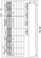
- FIG. 3 is a schematic diagram illustrating an example of the connection management screen.
- the connection management screen is a main screen displayed immediately after the integrated management process is activated and displays the machine tools 20 serving as a management target of the integrated management process, connection settings or data save destinations of respective measurement tools, and the like as a list.
- the connection management screen includes menu buttons including “file” and “help”, a display region of “connection setting list”, buttons of “add setting”, “delete setting”, “start measurement”, and “stop measurement”, and an error log display region.
- connection setting list The names of the machine tools 20 serving as management targets of the integrated management process and the connection settings of the respective machine tools 20 are displayed in the display region of “connection setting list”.
- a checkbox is displayed in the display region of “connection setting list” so as to correspond to the name of each machine tool 20 .
- a measurement tool corresponding to the machine tool 20 is activated on the basis of the connection setting.
- the save destinations of the measurement setting file and the measurement data save file are displayed in the display region of “connection setting list” so as to correspond to the name of each machine tool 20 .
- the “add setting” button is a button for adding a new connection setting for the machine tool 20 .
- the screen transitions to a connection setting screen for performing a new connection setting.
- the “delete setting” button is a button for deleting the selected connection setting.
- the “start measurement” button is a button for starting (activating the measurement tool) measurement on the machine tool 20 being in an online state among the connection settings displayed as the “connection setting list”.
- the “stop measurement” button is a button for stopping (stopping the measurement tool) measurement on the machine tool 20 .
- the error log display region is a region for displaying the details of an error when an error occurs in measurement on the machine tool 20 by the measurement tool.
- FIG. 4 is a schematic diagram illustrating an example of the connection setting screen.
- the connection setting screen is displayed when the “add setting” button is operated or the connection setting is selected and is a display screen for performing a connection setting for the machine tool 20 .
- respective items of “machine name”, “save name”, “save directory”, “measurement setting file”, “IP address”, “port number”, and “timeout” are displayed in the connection setting screen so that the items can be set.
- the “machine name” item is an item for setting the name of the machine tool 20 serving as a management target of the integrated management process.
- the “save name” item is an item for setting a save file name (a measurement data save file name) when the measurement tool saves measurement data.
- the “save directory” item is an item for setting a save destination directory name when the measurement tool saves measurement data.
- the “measurement setting file” item is an item for setting a file name (a measurement setting file name) that stores various settings of individual measurement tools, such as a connection setting of a measurement tool and the setting of the types of the measurement data.
- the “IP address” is an item for setting an IP address of the machine tool 20 serving as a management target of the integrated management process.
- the “port number” is an item for setting a port number of the machine tool 20 serving as a management target of the integrated management process.
- the “timeout” is an item for setting the length of a waiting period until the measurement tool can communicate with the machine tool 20 .
- the connection setting screen is closed by applying the input settings to the measurement setting file.
- the connection setting screen is closed without applying the input settings to the measurement setting file.
- FIGS. 5A to 5C are schematic diagrams illustrating an example of the connection status display screen.
- the connection status display screen is a screen for displaying a connection state of the machine tool 20 for which a check mark is input to the checkbox of the “connection setting list” in the connection management screen.
- the example illustrated in FIG. 5A illustrates a state in which the connection to the machine tool 20 (Machine1) registered on the first row of the “connection setting list” is successful.
- an indication for identifying success in connection is displayed (for example, the background is displayed in blue).
- FIG. 5B illustrates a state in which the connection to the machine tool 20 (Machine1) registered on the first row of the “connection setting list” is successful whereas the connection to the machine tool 20 (Machine2) registered on the second row of the “connection setting list” is not successful.
- an indication for identifying a failure in connection is displayed (for example, the background is displayed in red).
- FIG. 5C illustrates a state in which measurement for the machine tool 20 (Machine1) registered on the first row of the “connection setting list” is started.
- an indication for identifying the start of measurement is displayed (for example, the background is displayed in green).
- FIG. 6 is a flowchart illustrating the flow of an integrated management process executed by the data collection management device 10 .
- the integrated management process starts when an instruction to activate the integrated management process is input via the input unit 14 .
- step S 1 the UI display control unit 11 a displays the connection management screen.
- step S 2 the UI display control unit 11 a determines whether an operation is performed on the connection management screen. When an operation is not performed on the connection management screen, a determination result of NO is obtained in step S 2 and the process of step S 2 is repeated. On the other hand, when an operation is performed on the connection management screen, a determination result of YES is obtained in step S 2 and the flow proceeds to step S 3 .
- step S 3 the UI display control unit 11 a determines whether the operation on the connection management screen is an operation on the menu button.
- a determination result of YES is obtained in step S 3 and the flow proceeds to step S 4 .
- a determination result of NO is obtained in step S 3 and the flow proceeds to step S 5 .
- step S 4 the UI display control unit 11 a executes various commands corresponding to the content of the operation on the menu button.
- step S 5 the UI display control unit 11 a determines whether the operation on the connection management screen is an operation of instructing transition to the connection setting screen.
- a determination result of YES is obtained in step S 5 and the flow proceeds to step S 6 .
- step S 7 a determination result of NO is obtained in step S 5 and the flow proceeds to step S 7 .
- step S 6 the UI display control unit 11 a receives the input of various items in the connection setting screen.
- step S 7 the flow proceeds to step S 7 by applying the input settings to the measurement setting file.
- step S 7 the flow proceeds to step S 7 without applying the input setting to the measurement setting file.
- step S 7 the UI display control unit 11 a determines whether the operation on the connection management screen is the input of a check mark to the checkbox.
- a determination result of YES is obtained in step S 7 and the flow proceeds to step S 8 .
- a determination result of NO is obtained in step S 7 and the flow proceeds to step S 10 .
- step S 8 the measurement tool execution management unit 11 c activates a measurement tool corresponding to the machine tool 20 on the basis of the connection setting of the machine tool 20 for which a check mark is input.
- step S 9 the UI display control unit 11 a displays a connection status screen according to the connection state of the measurement tool.
- step S 10 the UI display control unit 11 a determines whether the operation on the connection management screen is an operation on the “start measurement” button. When the operation on the connection management screen is an operation on the “start measurement” button, a determination result of YES is obtained in step S 10 and the flow proceeds to step S 11 .
- step S 10 when the operation on the connection management screen is not the operation on the “start measurement” button, a determination result of NO is obtained in step S 10 and the flow proceeds to step S 15 .
- step S 11 the measurement tool execution management unit 11 c reads a measurement setting file of the machine tool 20 which has succeeded in connection.
- step S 12 the measurement tool execution management unit 11 c transmits the setting based on the measurement setting file for the machine tool 20 and a measurement start command using the measurement tool.
- step S 13 the measurement tool execution management unit 11 c acquires a measurement status (measuring, the presence of an error, or the like) from the machine tool 20 using the measurement tool.
- step S 14 the measurement tool execution management unit 11 c stores the measurement data acquired from the machine tool 20 in the measurement data save file using the measurement tool.
- step S 15 the UI display control unit 11 a determines whether the operation on the connection management screen is an operation on the “delete setting” button.
- a determination result of YES is obtained in step S 15 and the flow proceeds to step S 16 .
- the setting management unit 11 b deletes the selected connection setting.
- step S 17 the setting management unit 11 b stores the management file by applying the deletion of the connection setting to the management file. After step S 17 , the integrated management process is repeated.
- the data collection management device 10 performs connection settings stored therein and setting of the types of measurement data with respect to the measurement tool corresponding to each of the plurality of machine tools 20 and executes measurement of each of the machine tools 20 using the measurement tool. Due to this, in the data collection management system 1 , the user can manage the plurality of machine tools 20 using the data collection management device 10 in an integrated manner. Therefore, according to the data collection management system 1 , it is possible to alleviate the work load of managing the plurality of machine tools 20 more appropriately.
- the measurement tool execution management unit 11 c of the data collection management device 10 acquires measurement data on the machine tool 20 . Therefore, the data collection management device 10 can manage the measurement data of each of the machine tools 20 .
- the data collection management device 10 includes the measurement tool corresponding to each of the machine tools 20 . Therefore, the data collection management device 10 can activate the measurement tool of the machine tool 20 and control measurement of data on the machine tool 20 directly.
- the data collection management device 10 includes the UI display control unit 11 a that displays an interface screen (the connection management screen or the like) for controlling the connection settings on the measurement tool and the setting of the types of the measurement data and execution of the measurement on the respective machine tools 20 by the measurement tool.
- the UI display control unit 11 a displays the machine tools 20 serving as measurement targets on the interface screen as a list, and when an item of the machine tool 20 displayed as the list is selected, processes related to setting on the measurement tool corresponding to the machine tool. 20 , connection by communication with the machine tool 20 , or measurement on the machine tool 20 are executed. In this way, the user can perform processes related to setting on the measurement tool corresponding to the machine tool 20 , connection by communication with the machine tool, or measurement on the machine tool with a simple operation.
- the UI display control unit 11 a receives addition and deletion of the machine tool 20 serving as the measurement target on the interface screen. In this way, even when the number of machine tools 20 serving as the measurement target increases or decreases, it is possible to set an integrated management target machine tool 20 with a simple operation.
- the data collection management device 10 includes the measurement tool and the measurement tool execution management unit 11 c .
- the data collection management device 10 may include the measurement tool execution management unit 11 c
- an information processing device different from the data collection management device 10 may include the measurement tool.
- FIG. 7 is a schematic diagram illustrating a system configuration of the data collection management system 1 in which the measurement tool and the measurement tool execution management unit 11 c are provided in different information processing devices.
- information processing devices 10 - 1 to 10 - m each including a plurality of measurement tools corresponding to a plurality of predetermined machine tools 20 (for example, machine tools 20 within a dash line) may be provided in each of the plurality of machine tools 20 , and the data collection management device 10 may manage the measurement tools provided in the plurality of information processing devices 10 - 1 to 10 - m via the network 30 in an integrated manner.
- the processing load of the data collection management system 1 can be distributed.
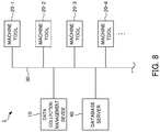
- FIG. 8 is a schematic diagram illustrating a system configuration of the data collection management system 1 in which the measurement data save file is stored in a storage device on the network 30 .
- the data collection management system 1 may include a database server 40 that can communicate with the data collection management device 10 via the network 30 , and the data collection management device 10 may store the measurement data acquired using the measurement tool in a measurement data save file stored in the database sever 40 .
- the data collection management device 10 may store the measurement data acquired using the measurement tool in a measurement data save file stored in the database sever 40 .
- the data collection management device 10 may acquire a measurement tool set in advance for the machine tool, extract settings from the measurement tool, and add a measurement setting file and a management file for the integrated management process automatically. In this case, it is possible to add the machine tool 20 as an integrated management target of the data collection management system 1 easily.
- the measurement target is not limited thereto. That is, various parameters of the machine tool may be used as the measurement target of the measurement tool.
- Various functions of the data collection management device 10 can be installed in a plurality of information processing devices of the data collection management system 1 in a distributed manner, and the integrated management function may be realized by the data collection management system 1 as a whole.
- the data collection management device 10 or the information processing devices 10 - 1 to 10 - m may perform integrated management with respect to the machine tools 20 provided outside the data collection management system 1 rather than including the machine tools 20 in the data collection management system 1 of the present embodiment.
- All or some of the functions of the data collection management system 1 of the above-described embodiment may be realized by hardware, software, or a combination thereof.
- the function being realized by software means that the function is realized when a processor reads and executes a program.
- some or all of the functions of the data collection management system 1 may be realized by an integrated circuit (IC) such as an application specific integrated circuit (ASIC), a gate array, a field programmable gate array (FPGA), or a complex programmable logic device (CPLD), for example.
- IC integrated circuit
- ASIC application specific integrated circuit
- FPGA field programmable gate array
- CPLD complex programmable logic device
- the function can be realized when a computer including a storage unit such as a hard disk or ROM, storing a program that describes all or some of the operations of the data collection management system, a DRAM storing data necessary for computation, a CPU, and a bus connecting respective units stores information necessary for computation in the DRAM and causes the CPU to operate the program.
- a computer including a storage unit such as a hard disk or ROM, storing a program that describes all or some of the operations of the data collection management system, a DRAM storing data necessary for computation, a CPU, and a bus connecting respective units stores information necessary for computation in the DRAM and causes the CPU to operate the program.
- the computer readable media include various types of tangible storage medium.
- Examples of the computer readable media include a magnetic storage medium (for example, a flexible disk, a magnetic tape, and a hard disk drive), a magneto-optical storage medium (for example, a magneto-optical disc), a read only memory (CR-ROM), a CD-R, a CD-R/W, and a semiconductor memory (for example, a mask ROM, a programmable ROM (PROM), an erasable PROM (EPROM), a flash memory, and a random access memory (RAM)).
- These programs may be distributed by being downloaded to a computer of a user via a network.
Landscapes
- Engineering & Computer Science (AREA)
- General Physics & Mathematics (AREA)
- Physics & Mathematics (AREA)
- Theoretical Computer Science (AREA)
- General Engineering & Computer Science (AREA)
- Manufacturing & Machinery (AREA)
- Automation & Control Theory (AREA)
- Databases & Information Systems (AREA)
- Data Mining & Analysis (AREA)
- Software Systems (AREA)
- Quality & Reliability (AREA)
- Human Computer Interaction (AREA)
- General Factory Administration (AREA)
- Numerical Control (AREA)
Abstract
Description
- Patent Document 1: Japanese Unexamined Patent Application, Publication No. 2009-48324
the data collection management device includes:
a setting storage unit (for example, a
a setting unit (for example, a
an execution management unit (for example, a measurement tool
- 1: Data collection management system
- 10: Data collection management device
- 11: CPU
- 11 a: UI display control unit
- 11 b: Setting management unit
- 12 c: Measurement tool execution management unit
- 12: ROM
- 13: RAM
- 14: Input unit
- 15: Display unit
- 16: Storage unit
- 17: Communication unit
- 10-1 to 10-n: Information processing device
- 20, 20-1 to 20-n: Machine tool
- 30: Network
- 40: Database server
Claims (11)
Applications Claiming Priority (2)
| Application Number | Priority Date | Filing Date | Title |
|---|---|---|---|
| JP2017072112A JP6499706B2 (en) | 2017-03-31 | 2017-03-31 | Data collection management system, data collection management method and program for managing data collection of a plurality of machines |
| JP2017-072112 | 2017-03-31 |
Publications (2)
| Publication Number | Publication Date |
|---|---|
| US20180285395A1 US20180285395A1 (en) | 2018-10-04 |
| US10698872B2 true US10698872B2 (en) | 2020-06-30 |
Family
ID=63524652
Family Applications (1)
| Application Number | Title | Priority Date | Filing Date |
|---|---|---|---|
| US15/922,075 Active US10698872B2 (en) | 2017-03-31 | 2018-03-15 | Data collection management system, method, and recording medium encoded with a program for managing collection of data of plurality of machines |
Country Status (4)
| Country | Link |
|---|---|
| US (1) | US10698872B2 (en) |
| JP (1) | JP6499706B2 (en) |
| CN (1) | CN108693830B (en) |
| DE (1) | DE102018204224A1 (en) |
Families Citing this family (7)
| Publication number | Priority date | Publication date | Assignee | Title |
|---|---|---|---|---|
| JP6703967B2 (en) * | 2017-08-08 | 2020-06-03 | Dmg森精機株式会社 | Tool management device and machine tool equipped with the same |
| JP7043782B2 (en) * | 2017-10-20 | 2022-03-30 | オムロン株式会社 | Servo motor adjustment device and servo motor adjustment method |
| KR102147487B1 (en) * | 2018-12-28 | 2020-08-24 | (주) 유노믹 | Agent-based machine tool data collection method |
| AT522653B1 (en) * | 2019-05-15 | 2025-12-15 | Wittmann Tech Gmbh | Methods for the representation and operation of production equipment, especially for the plastics processing industry |
| JP2020197835A (en) | 2019-05-31 | 2020-12-10 | ファナック株式会社 | Data collection and setting device for industrial machine |
| JP2020197836A (en) * | 2019-05-31 | 2020-12-10 | ファナック株式会社 | Data collection and checking device for industrial machine |
| CN110457312B (en) * | 2019-07-05 | 2023-07-07 | 中国平安财产保险股份有限公司 | Method, device, equipment and readable storage medium for collecting multi-type data |
Citations (9)
| Publication number | Priority date | Publication date | Assignee | Title |
|---|---|---|---|---|
| JPH09248739A (en) | 1996-03-14 | 1997-09-22 | Hitachi Ltd | Operation status monitoring device |
| JPH11338535A (en) | 1998-05-22 | 1999-12-10 | Mitsubishi Electric Corp | Production equipment maintenance data monitoring system |
| US20050144264A1 (en) | 2002-03-08 | 2005-06-30 | Michael Gruhn | Diagnosis system for at least one technical system |
| CN1906550A (en) | 2004-01-06 | 2007-01-31 | 瑞尼斯豪公司 | Machine tool workpiece inspection system |
| JP2009048324A (en) | 2007-08-16 | 2009-03-05 | Fujitsu Microelectronics Ltd | Monitoring system and monitoring method |
| CN102356645A (en) | 2009-03-16 | 2012-02-15 | 三菱电机株式会社 | Data gathering device |
| EP2490161A1 (en) | 2007-09-28 | 2012-08-22 | Fisher-Rosemount Systems, Inc. | Methods and apparatus to standardize data properties in a process control environment |
| US20150256597A1 (en) * | 2014-03-04 | 2015-09-10 | Home Controls, LLC | System and Method for Property Data Collection and Management |
| JP2016162402A (en) | 2015-03-05 | 2016-09-05 | ファナック株式会社 | Data measurement device for measuring physical data by switching communication destination |
-
2017
- 2017-03-31 JP JP2017072112A patent/JP6499706B2/en active Active
-
2018
- 2018-03-15 US US15/922,075 patent/US10698872B2/en active Active
- 2018-03-20 DE DE102018204224.1A patent/DE102018204224A1/en active Pending
- 2018-03-27 CN CN201810258610.XA patent/CN108693830B/en active Active
Patent Citations (9)
| Publication number | Priority date | Publication date | Assignee | Title |
|---|---|---|---|---|
| JPH09248739A (en) | 1996-03-14 | 1997-09-22 | Hitachi Ltd | Operation status monitoring device |
| JPH11338535A (en) | 1998-05-22 | 1999-12-10 | Mitsubishi Electric Corp | Production equipment maintenance data monitoring system |
| US20050144264A1 (en) | 2002-03-08 | 2005-06-30 | Michael Gruhn | Diagnosis system for at least one technical system |
| CN1906550A (en) | 2004-01-06 | 2007-01-31 | 瑞尼斯豪公司 | Machine tool workpiece inspection system |
| JP2009048324A (en) | 2007-08-16 | 2009-03-05 | Fujitsu Microelectronics Ltd | Monitoring system and monitoring method |
| EP2490161A1 (en) | 2007-09-28 | 2012-08-22 | Fisher-Rosemount Systems, Inc. | Methods and apparatus to standardize data properties in a process control environment |
| CN102356645A (en) | 2009-03-16 | 2012-02-15 | 三菱电机株式会社 | Data gathering device |
| US20150256597A1 (en) * | 2014-03-04 | 2015-09-10 | Home Controls, LLC | System and Method for Property Data Collection and Management |
| JP2016162402A (en) | 2015-03-05 | 2016-09-05 | ファナック株式会社 | Data measurement device for measuring physical data by switching communication destination |
Non-Patent Citations (3)
| Title |
|---|
| Notification of Reasons for Refusal dated Nov. 6, 2018 in corresponding Japanese Application No. 2017-072112. |
| Office Action dated Dec. 4, 2019 in DE Patent Application No. 102018204224.1. |
| Office Action dated Jul. 23, 2019 in CN Patent Application No. 201810258610.X. |
Also Published As
| Publication number | Publication date |
|---|---|
| CN108693830A (en) | 2018-10-23 |
| CN108693830B (en) | 2020-02-21 |
| JP2018173858A (en) | 2018-11-08 |
| JP6499706B2 (en) | 2019-04-10 |
| DE102018204224A1 (en) | 2018-10-04 |
| US20180285395A1 (en) | 2018-10-04 |
Similar Documents
| Publication | Publication Date | Title |
|---|---|---|
| US10698872B2 (en) | Data collection management system, method, and recording medium encoded with a program for managing collection of data of plurality of machines | |
| US11301122B2 (en) | Servo motor adjusting device and servo motor adjusting method | |
| TW202034343A (en) | Method, computer apparatus, and user interface for performing automatic testing upon storage devices | |
| US9513957B2 (en) | Management system, management program, and management method | |
| JP2015176370A (en) | Control system, method, program and information processor | |
| US10261716B2 (en) | Programmable display, update processing apparatus, updating method, information processing method, and program stored on computer-readable recording medium | |
| CN107407922B (en) | Programmable logic controller, method of controlling the same, and recording medium | |
| CN107357264A (en) | Method and apparatus for optimizing process control system | |
| US20200272126A1 (en) | Screen creation device and screen creation system | |
| JP2017156953A5 (en) | Automatic installation system, information processing apparatus, information processing apparatus control method, and program | |
| TW201633028A (en) | Processing condition management system and production system | |
| US10296241B2 (en) | Control device, control system, control method for control device, and control method for control system | |
| JP6442131B2 (en) | Control system and control device | |
| JP2012141722A (en) | Setting device | |
| WO2023248471A1 (en) | Monitoring device and robot monitoring system | |
| US10108187B2 (en) | Control device, control system, support device, and control-device maintenance management method | |
| US20250258474A1 (en) | Setting assistance device, control system, setting assistance method, and program | |
| KR101981910B1 (en) | Programmable indicator | |
| CN113031523A (en) | Numerical control machine on-line system and management method thereof | |
| WO2021100308A1 (en) | Machine tool, log output method and log output program | |
| KR20170078172A (en) | Method and Apparatus for remote management | |
| KR101896081B1 (en) | Apparatus for displaying menu of HMI program | |
| US20240302806A1 (en) | Information processing device and computer-readable storage medium | |
| EP4270128B1 (en) | Monitoring device, display method, program, and monitoring system | |
| WO2021200653A1 (en) | Control device |
Legal Events
| Date | Code | Title | Description |
|---|---|---|---|
| AS | Assignment |
Owner name: FANUC CORPORATION, JAPAN Free format text: ASSIGNMENT OF ASSIGNORS INTEREST;ASSIGNORS:LUO, WEI;TEZUKA, JUNICHI;REEL/FRAME:045237/0374 Effective date: 20180308 |
|
| FEPP | Fee payment procedure |
Free format text: ENTITY STATUS SET TO UNDISCOUNTED (ORIGINAL EVENT CODE: BIG.); ENTITY STATUS OF PATENT OWNER: LARGE ENTITY |
|
| STPP | Information on status: patent application and granting procedure in general |
Free format text: DOCKETED NEW CASE - READY FOR EXAMINATION |
|
| STPP | Information on status: patent application and granting procedure in general |
Free format text: NON FINAL ACTION MAILED |
|
| STPP | Information on status: patent application and granting procedure in general |
Free format text: RESPONSE TO NON-FINAL OFFICE ACTION ENTERED AND FORWARDED TO EXAMINER |
|
| STPP | Information on status: patent application and granting procedure in general |
Free format text: FINAL REJECTION MAILED |
|
| STPP | Information on status: patent application and granting procedure in general |
Free format text: ADVISORY ACTION MAILED |
|
| STPP | Information on status: patent application and granting procedure in general |
Free format text: NOTICE OF ALLOWANCE MAILED -- APPLICATION RECEIVED IN OFFICE OF PUBLICATIONS |
|
| STCF | Information on status: patent grant |
Free format text: PATENTED CASE |
|
| MAFP | Maintenance fee payment |
Free format text: PAYMENT OF MAINTENANCE FEE, 4TH YEAR, LARGE ENTITY (ORIGINAL EVENT CODE: M1551); ENTITY STATUS OF PATENT OWNER: LARGE ENTITY Year of fee payment: 4 |