US10698418B2 - Target-following carrier - Google Patents
Target-following carrier Download PDFInfo
- Publication number
- US10698418B2 US10698418B2 US16/056,685 US201816056685A US10698418B2 US 10698418 B2 US10698418 B2 US 10698418B2 US 201816056685 A US201816056685 A US 201816056685A US 10698418 B2 US10698418 B2 US 10698418B2
- Authority
- US
- United States
- Prior art keywords
- target
- module
- distance
- signal transmitting
- moving
- Prior art date
- Legal status (The legal status is an assumption and is not a legal conclusion. Google has not performed a legal analysis and makes no representation as to the accuracy of the status listed.)
- Active, expires
Links
Images


Classifications
-
- G—PHYSICS
- G08—SIGNALLING
- G08B—SIGNALLING SYSTEMS, e.g. PERSONAL CALLING SYSTEMS; ORDER TELEGRAPHS; ALARM SYSTEMS
- G08B5/00—Visible signalling systems, e.g. visible personal calling systems or remote indication of seats occupied
- G08B5/22—Visible signalling systems, e.g. visible personal calling systems or remote indication of seats occupied using electric transmission; using electromagnetic transmission
- G08B5/36—Visible signalling systems, e.g. visible personal calling systems or remote indication of seats occupied using electric transmission; using electromagnetic transmission using visible light sources
-
- G—PHYSICS
- G05—CONTROLLING; REGULATING
- G05D—SYSTEMS FOR CONTROLLING OR REGULATING NON-ELECTRIC VARIABLES
- G05D1/00—Control of position, course, altitude or attitude of land, water, air or space vehicles, e.g. using automatic pilots
- G05D1/02—Control of position or course in two dimensions
- G05D1/021—Control of position or course in two dimensions specially adapted to land vehicles
- G05D1/0276—Control of position or course in two dimensions specially adapted to land vehicles using signals provided by a source external to the vehicle
- G05D1/028—Control of position or course in two dimensions specially adapted to land vehicles using signals provided by a source external to the vehicle using a RF signal
-
- B—PERFORMING OPERATIONS; TRANSPORTING
- B60—VEHICLES IN GENERAL
- B60L—PROPULSION OF ELECTRICALLY-PROPELLED VEHICLES; SUPPLYING ELECTRIC POWER FOR AUXILIARY EQUIPMENT OF ELECTRICALLY-PROPELLED VEHICLES; ELECTRODYNAMIC BRAKE SYSTEMS FOR VEHICLES IN GENERAL; MAGNETIC SUSPENSION OR LEVITATION FOR VEHICLES; MONITORING OPERATING VARIABLES OF ELECTRICALLY-PROPELLED VEHICLES; ELECTRIC SAFETY DEVICES FOR ELECTRICALLY-PROPELLED VEHICLES
- B60L15/00—Methods, circuits, or devices for controlling the traction-motor speed of electrically-propelled vehicles
- B60L15/20—Methods, circuits, or devices for controlling the traction-motor speed of electrically-propelled vehicles for control of the vehicle or its driving motor to achieve a desired performance, e.g. speed, torque, programmed variation of speed
- B60L15/2036—Electric differentials, e.g. for supporting steering vehicles
-
- B—PERFORMING OPERATIONS; TRANSPORTING
- B60—VEHICLES IN GENERAL
- B60L—PROPULSION OF ELECTRICALLY-PROPELLED VEHICLES; SUPPLYING ELECTRIC POWER FOR AUXILIARY EQUIPMENT OF ELECTRICALLY-PROPELLED VEHICLES; ELECTRODYNAMIC BRAKE SYSTEMS FOR VEHICLES IN GENERAL; MAGNETIC SUSPENSION OR LEVITATION FOR VEHICLES; MONITORING OPERATING VARIABLES OF ELECTRICALLY-PROPELLED VEHICLES; ELECTRIC SAFETY DEVICES FOR ELECTRICALLY-PROPELLED VEHICLES
- B60L50/00—Electric propulsion with power supplied within the vehicle
- B60L50/50—Electric propulsion with power supplied within the vehicle using propulsion power supplied by batteries or fuel cells
-
- B—PERFORMING OPERATIONS; TRANSPORTING
- B60—VEHICLES IN GENERAL
- B60Q—ARRANGEMENT OF SIGNALLING OR LIGHTING DEVICES, THE MOUNTING OR SUPPORTING THEREOF OR CIRCUITS THEREFOR, FOR VEHICLES IN GENERAL
- B60Q9/00—Arrangement or adaptation of signal devices not provided for in one of main groups B60Q1/00 - B60Q7/00, e.g. haptic signalling
-
- G—PHYSICS
- G01—MEASURING; TESTING
- G01S—RADIO DIRECTION-FINDING; RADIO NAVIGATION; DETERMINING DISTANCE OR VELOCITY BY USE OF RADIO WAVES; LOCATING OR PRESENCE-DETECTING BY USE OF THE REFLECTION OR RERADIATION OF RADIO WAVES; ANALOGOUS ARRANGEMENTS USING OTHER WAVES
- G01S13/00—Systems using the reflection or reradiation of radio waves, e.g. radar systems; Analogous systems using reflection or reradiation of waves whose nature or wavelength is irrelevant or unspecified
- G01S13/66—Radar-tracking systems; Analogous systems
- G01S13/72—Radar-tracking systems; Analogous systems for two-dimensional [2D] tracking, e.g. combination of angle and range tracking, track-while-scan radar
-
- G—PHYSICS
- G01—MEASURING; TESTING
- G01S—RADIO DIRECTION-FINDING; RADIO NAVIGATION; DETERMINING DISTANCE OR VELOCITY BY USE OF RADIO WAVES; LOCATING OR PRESENCE-DETECTING BY USE OF THE REFLECTION OR RERADIATION OF RADIO WAVES; ANALOGOUS ARRANGEMENTS USING OTHER WAVES
- G01S13/00—Systems using the reflection or reradiation of radio waves, e.g. radar systems; Analogous systems using reflection or reradiation of waves whose nature or wavelength is irrelevant or unspecified
- G01S13/86—Combinations of radar systems with non-radar systems, e.g. sonar, direction finder
- G01S13/865—Combination of radar systems with lidar systems
-
- G—PHYSICS
- G01—MEASURING; TESTING
- G01S—RADIO DIRECTION-FINDING; RADIO NAVIGATION; DETERMINING DISTANCE OR VELOCITY BY USE OF RADIO WAVES; LOCATING OR PRESENCE-DETECTING BY USE OF THE REFLECTION OR RERADIATION OF RADIO WAVES; ANALOGOUS ARRANGEMENTS USING OTHER WAVES
- G01S17/00—Systems using the reflection or reradiation of electromagnetic waves other than radio waves, e.g. lidar systems
- G01S17/02—Systems using the reflection of electromagnetic waves other than radio waves
- G01S17/06—Systems determining position data of a target
- G01S17/08—Systems determining position data of a target for measuring distance only
-
- G—PHYSICS
- G01—MEASURING; TESTING
- G01S—RADIO DIRECTION-FINDING; RADIO NAVIGATION; DETERMINING DISTANCE OR VELOCITY BY USE OF RADIO WAVES; LOCATING OR PRESENCE-DETECTING BY USE OF THE REFLECTION OR RERADIATION OF RADIO WAVES; ANALOGOUS ARRANGEMENTS USING OTHER WAVES
- G01S17/00—Systems using the reflection or reradiation of electromagnetic waves other than radio waves, e.g. lidar systems
- G01S17/02—Systems using the reflection of electromagnetic waves other than radio waves
- G01S17/06—Systems determining position data of a target
- G01S17/46—Indirect determination of position data
- G01S17/48—Active triangulation systems, i.e. using the transmission and reflection of electromagnetic waves other than radio waves
-
- G—PHYSICS
- G01—MEASURING; TESTING
- G01S—RADIO DIRECTION-FINDING; RADIO NAVIGATION; DETERMINING DISTANCE OR VELOCITY BY USE OF RADIO WAVES; LOCATING OR PRESENCE-DETECTING BY USE OF THE REFLECTION OR RERADIATION OF RADIO WAVES; ANALOGOUS ARRANGEMENTS USING OTHER WAVES
- G01S17/00—Systems using the reflection or reradiation of electromagnetic waves other than radio waves, e.g. lidar systems
- G01S17/87—Combinations of systems using electromagnetic waves other than radio waves
-
- G—PHYSICS
- G05—CONTROLLING; REGULATING
- G05D—SYSTEMS FOR CONTROLLING OR REGULATING NON-ELECTRIC VARIABLES
- G05D1/00—Control of position, course, altitude or attitude of land, water, air or space vehicles, e.g. using automatic pilots
- G05D1/02—Control of position or course in two dimensions
- G05D1/021—Control of position or course in two dimensions specially adapted to land vehicles
- G05D1/0231—Control of position or course in two dimensions specially adapted to land vehicles using optical position detecting means
- G05D1/0234—Control of position or course in two dimensions specially adapted to land vehicles using optical position detecting means using optical markers or beacons
- G05D1/0236—Control of position or course in two dimensions specially adapted to land vehicles using optical position detecting means using optical markers or beacons in combination with a laser
-
- G—PHYSICS
- G05—CONTROLLING; REGULATING
- G05D—SYSTEMS FOR CONTROLLING OR REGULATING NON-ELECTRIC VARIABLES
- G05D1/00—Control of position, course, altitude or attitude of land, water, air or space vehicles, e.g. using automatic pilots
- G05D1/02—Control of position or course in two dimensions
- G05D1/021—Control of position or course in two dimensions specially adapted to land vehicles
- G05D1/0231—Control of position or course in two dimensions specially adapted to land vehicles using optical position detecting means
- G05D1/0238—Control of position or course in two dimensions specially adapted to land vehicles using optical position detecting means using obstacle or wall sensors
- G05D1/024—Control of position or course in two dimensions specially adapted to land vehicles using optical position detecting means using obstacle or wall sensors in combination with a laser
-
- G—PHYSICS
- G08—SIGNALLING
- G08B—SIGNALLING SYSTEMS, e.g. PERSONAL CALLING SYSTEMS; ORDER TELEGRAPHS; ALARM SYSTEMS
- G08B21/00—Alarms responsive to a single specified undesired or abnormal condition and not otherwise provided for
- G08B21/18—Status alarms
- G08B21/24—Reminder alarms, e.g. anti-loss alarms
-
- G—PHYSICS
- G08—SIGNALLING
- G08B—SIGNALLING SYSTEMS, e.g. PERSONAL CALLING SYSTEMS; ORDER TELEGRAPHS; ALARM SYSTEMS
- G08B25/00—Alarm systems in which the location of the alarm condition is signalled to a central station, e.g. fire or police telegraphic systems
- G08B25/01—Alarm systems in which the location of the alarm condition is signalled to a central station, e.g. fire or police telegraphic systems characterised by the transmission medium
- G08B25/10—Alarm systems in which the location of the alarm condition is signalled to a central station, e.g. fire or police telegraphic systems characterised by the transmission medium using wireless transmission systems
-
- G—PHYSICS
- G08—SIGNALLING
- G08B—SIGNALLING SYSTEMS, e.g. PERSONAL CALLING SYSTEMS; ORDER TELEGRAPHS; ALARM SYSTEMS
- G08B6/00—Tactile signalling systems, e.g. tactile personal calling systems
-
- H—ELECTRICITY
- H04—ELECTRIC COMMUNICATION TECHNIQUE
- H04W—WIRELESS COMMUNICATION NETWORKS
- H04W76/00—Connection management
- H04W76/10—Connection setup
-
- B—PERFORMING OPERATIONS; TRANSPORTING
- B60—VEHICLES IN GENERAL
- B60L—PROPULSION OF ELECTRICALLY-PROPELLED VEHICLES; SUPPLYING ELECTRIC POWER FOR AUXILIARY EQUIPMENT OF ELECTRICALLY-PROPELLED VEHICLES; ELECTRODYNAMIC BRAKE SYSTEMS FOR VEHICLES IN GENERAL; MAGNETIC SUSPENSION OR LEVITATION FOR VEHICLES; MONITORING OPERATING VARIABLES OF ELECTRICALLY-PROPELLED VEHICLES; ELECTRIC SAFETY DEVICES FOR ELECTRICALLY-PROPELLED VEHICLES
- B60L2200/00—Type of vehicles
- B60L2200/30—Trolleys
-
- B—PERFORMING OPERATIONS; TRANSPORTING
- B60—VEHICLES IN GENERAL
- B60L—PROPULSION OF ELECTRICALLY-PROPELLED VEHICLES; SUPPLYING ELECTRIC POWER FOR AUXILIARY EQUIPMENT OF ELECTRICALLY-PROPELLED VEHICLES; ELECTRODYNAMIC BRAKE SYSTEMS FOR VEHICLES IN GENERAL; MAGNETIC SUSPENSION OR LEVITATION FOR VEHICLES; MONITORING OPERATING VARIABLES OF ELECTRICALLY-PROPELLED VEHICLES; ELECTRIC SAFETY DEVICES FOR ELECTRICALLY-PROPELLED VEHICLES
- B60L2240/00—Control parameters of input or output; Target parameters
- B60L2240/60—Navigation input
- B60L2240/62—Vehicle position
-
- B—PERFORMING OPERATIONS; TRANSPORTING
- B60—VEHICLES IN GENERAL
- B60L—PROPULSION OF ELECTRICALLY-PROPELLED VEHICLES; SUPPLYING ELECTRIC POWER FOR AUXILIARY EQUIPMENT OF ELECTRICALLY-PROPELLED VEHICLES; ELECTRODYNAMIC BRAKE SYSTEMS FOR VEHICLES IN GENERAL; MAGNETIC SUSPENSION OR LEVITATION FOR VEHICLES; MONITORING OPERATING VARIABLES OF ELECTRICALLY-PROPELLED VEHICLES; ELECTRIC SAFETY DEVICES FOR ELECTRICALLY-PROPELLED VEHICLES
- B60L2260/00—Operating Modes
- B60L2260/20—Drive modes; Transition between modes
- B60L2260/32—Auto pilot mode
-
- G—PHYSICS
- G01—MEASURING; TESTING
- G01S—RADIO DIRECTION-FINDING; RADIO NAVIGATION; DETERMINING DISTANCE OR VELOCITY BY USE OF RADIO WAVES; LOCATING OR PRESENCE-DETECTING BY USE OF THE REFLECTION OR RERADIATION OF RADIO WAVES; ANALOGOUS ARRANGEMENTS USING OTHER WAVES
- G01S7/00—Details of systems according to groups G01S13/00, G01S15/00, G01S17/00
- G01S7/003—Transmission of data between radar, sonar or lidar systems and remote stations
- G01S7/006—Transmission of data between radar, sonar or lidar systems and remote stations using shared front-end circuitry, e.g. antennas
-
- G—PHYSICS
- G08—SIGNALLING
- G08B—SIGNALLING SYSTEMS, e.g. PERSONAL CALLING SYSTEMS; ORDER TELEGRAPHS; ALARM SYSTEMS
- G08B7/00—Signalling systems according to two or more of groups G08B3/00 - G08B6/00
- G08B7/06—Signalling systems according to two or more of groups G08B3/00 - G08B6/00 using electric transmission, e.g. involving audible and visible signalling through the use of sound and light sources
-
- Y—GENERAL TAGGING OF NEW TECHNOLOGICAL DEVELOPMENTS; GENERAL TAGGING OF CROSS-SECTIONAL TECHNOLOGIES SPANNING OVER SEVERAL SECTIONS OF THE IPC; TECHNICAL SUBJECTS COVERED BY FORMER USPC CROSS-REFERENCE ART COLLECTIONS [XRACs] AND DIGESTS
- Y02—TECHNOLOGIES OR APPLICATIONS FOR MITIGATION OR ADAPTATION AGAINST CLIMATE CHANGE
- Y02T—CLIMATE CHANGE MITIGATION TECHNOLOGIES RELATED TO TRANSPORTATION
- Y02T10/00—Road transport of goods or passengers
- Y02T10/60—Other road transportation technologies with climate change mitigation effect
- Y02T10/64—Electric machine technologies in electromobility
-
- Y—GENERAL TAGGING OF NEW TECHNOLOGICAL DEVELOPMENTS; GENERAL TAGGING OF CROSS-SECTIONAL TECHNOLOGIES SPANNING OVER SEVERAL SECTIONS OF THE IPC; TECHNICAL SUBJECTS COVERED BY FORMER USPC CROSS-REFERENCE ART COLLECTIONS [XRACs] AND DIGESTS
- Y02—TECHNOLOGIES OR APPLICATIONS FOR MITIGATION OR ADAPTATION AGAINST CLIMATE CHANGE
- Y02T—CLIMATE CHANGE MITIGATION TECHNOLOGIES RELATED TO TRANSPORTATION
- Y02T10/00—Road transport of goods or passengers
- Y02T10/60—Other road transportation technologies with climate change mitigation effect
- Y02T10/70—Energy storage systems for electromobility, e.g. batteries
-
- Y—GENERAL TAGGING OF NEW TECHNOLOGICAL DEVELOPMENTS; GENERAL TAGGING OF CROSS-SECTIONAL TECHNOLOGIES SPANNING OVER SEVERAL SECTIONS OF THE IPC; TECHNICAL SUBJECTS COVERED BY FORMER USPC CROSS-REFERENCE ART COLLECTIONS [XRACs] AND DIGESTS
- Y02—TECHNOLOGIES OR APPLICATIONS FOR MITIGATION OR ADAPTATION AGAINST CLIMATE CHANGE
- Y02T—CLIMATE CHANGE MITIGATION TECHNOLOGIES RELATED TO TRANSPORTATION
- Y02T10/00—Road transport of goods or passengers
- Y02T10/60—Other road transportation technologies with climate change mitigation effect
- Y02T10/72—Electric energy management in electromobility
-
- Y—GENERAL TAGGING OF NEW TECHNOLOGICAL DEVELOPMENTS; GENERAL TAGGING OF CROSS-SECTIONAL TECHNOLOGIES SPANNING OVER SEVERAL SECTIONS OF THE IPC; TECHNICAL SUBJECTS COVERED BY FORMER USPC CROSS-REFERENCE ART COLLECTIONS [XRACs] AND DIGESTS
- Y02—TECHNOLOGIES OR APPLICATIONS FOR MITIGATION OR ADAPTATION AGAINST CLIMATE CHANGE
- Y02T—CLIMATE CHANGE MITIGATION TECHNOLOGIES RELATED TO TRANSPORTATION
- Y02T90/00—Enabling technologies or technologies with a potential or indirect contribution to GHG emissions mitigation
- Y02T90/10—Technologies relating to charging of electric vehicles
- Y02T90/16—Information or communication technologies improving the operation of electric vehicles
Definitions
- the target following assembly may further comprise an antenna module, connected to the signal receiving RF module, for receiving the signals from the signal transmitting RF module.
- the antenna module may comprise: an omnidirectional antenna, receiving signals from the signal transmitting RF module for pairing and stopping operating after pairing is finished; and at least 3 directional antennas, each receiving signals from a specific range of horizontal angles, wherein a difference between central directional angles of the specific range of horizontal angles for any two directional antennas is a multiple of a fixed angle.
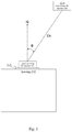
- FIG. 5 shows another arrangement of laser rangefinders.
- the moving module 220 is in charge of moving of the moving carrier 200 . It is integrated with the housing 210 and moves on the ground according to received commands. According to the present invention, the moving module 220 may further comprises some sub-modules as shown in FIG. 2 .
- the sub-modules are a wheel unit 221 , a motor 222 and a second control unit 223 .
- the wheel unit 221 is a component group and has at least two wheels. The wheels rotate to push, stop and turn the moving carrier 220 .
- the wheel unit 221 may be a couple of non-power wheels come with at least one power wheel. Some of the wheels can be controlled to change the direction of its rotation axis (directional wheel).
- the wheel unit 221 can also be a combination of universal wheels.
- step S 06 there may be extra steps after step S 06 .
- a first one is checking whether a difference between the directional angle and a relative angle between the normal direction and a connecting line from the first laser rangefinder to the target falls within a predetermined range of degrees (S 07 ).
- a second step is if a result of step S 07 is yes, repeating step S 06 ; if the result of step S 07 is no, repeating step S 02 and step S 03 .
- Steps S 07 and S 08 are used to deal with the situation that someone suddenly comes between the target and the laser rangefinders, causing different judgement of directions from the RF modules.
- the predetermined range of degrees is better +3% ⁇ 3%.
Landscapes
- Engineering & Computer Science (AREA)
- Physics & Mathematics (AREA)
- Radar, Positioning & Navigation (AREA)
- Remote Sensing (AREA)
- General Physics & Mathematics (AREA)
- Electromagnetism (AREA)
- Computer Networks & Wireless Communication (AREA)
- Mechanical Engineering (AREA)
- Aviation & Aerospace Engineering (AREA)
- Automation & Control Theory (AREA)
- Power Engineering (AREA)
- Transportation (AREA)
- Optics & Photonics (AREA)
- Emergency Management (AREA)
- Signal Processing (AREA)
- Business, Economics & Management (AREA)
- Human Computer Interaction (AREA)
- Life Sciences & Earth Sciences (AREA)
- Sustainable Development (AREA)
- Sustainable Energy (AREA)
- Optical Radar Systems And Details Thereof (AREA)
- Control Of Position, Course, Altitude, Or Attitude Of Moving Bodies (AREA)
Abstract
Description
Claims (18)
Priority Applications (2)
| Application Number | Priority Date | Filing Date | Title |
|---|---|---|---|
| US16/056,685 US10698418B2 (en) | 2018-08-07 | 2018-08-07 | Target-following carrier |
| US16/101,585 US10698419B2 (en) | 2018-08-07 | 2018-08-13 | Method and system for following target |
Applications Claiming Priority (1)
| Application Number | Priority Date | Filing Date | Title |
|---|---|---|---|
| US16/056,685 US10698418B2 (en) | 2018-08-07 | 2018-08-07 | Target-following carrier |
Related Child Applications (1)
| Application Number | Title | Priority Date | Filing Date |
|---|---|---|---|
| US16/101,585 Continuation US10698419B2 (en) | 2018-08-07 | 2018-08-13 | Method and system for following target |
Publications (2)
| Publication Number | Publication Date |
|---|---|
| US20200050203A1 US20200050203A1 (en) | 2020-02-13 |
| US10698418B2 true US10698418B2 (en) | 2020-06-30 |
Family
ID=69405989
Family Applications (2)
| Application Number | Title | Priority Date | Filing Date |
|---|---|---|---|
| US16/056,685 Active 2038-08-08 US10698418B2 (en) | 2018-08-07 | 2018-08-07 | Target-following carrier |
| US16/101,585 Active US10698419B2 (en) | 2018-08-07 | 2018-08-13 | Method and system for following target |
Family Applications After (1)
| Application Number | Title | Priority Date | Filing Date |
|---|---|---|---|
| US16/101,585 Active US10698419B2 (en) | 2018-08-07 | 2018-08-13 | Method and system for following target |
Country Status (1)
| Country | Link |
|---|---|
| US (2) | US10698418B2 (en) |
Families Citing this family (4)
| Publication number | Priority date | Publication date | Assignee | Title |
|---|---|---|---|---|
| US11383701B2 (en) * | 2019-04-26 | 2022-07-12 | Meng Ching | Obstacle avoiding guidance system |
| FI4201818T3 (en) * | 2020-08-20 | 2026-01-07 | Daifuku Kk | BAGGAGE CHECK-IN MACHINE |
| DE202022102322U1 (en) * | 2022-04-29 | 2023-08-01 | Robert Bosch Gesellschaft mit beschränkter Haftung | Communication unit with a fixing device for fixing to a component of a vehicle, in particular a single-track vehicle |
| DE202022102323U1 (en) * | 2022-04-29 | 2023-08-01 | Robert Bosch Gesellschaft mit beschränkter Haftung | Communication unit with a fixing device for fixing to a component of a vehicle, in particular a single-track vehicle |
Citations (15)
| Publication number | Priority date | Publication date | Assignee | Title |
|---|---|---|---|---|
| US6108636A (en) * | 1996-10-15 | 2000-08-22 | Iris Corporation Berhad | Luggage handling and reconciliation system using an improved security identification document including contactless communication insert unit |
| US6265975B1 (en) * | 2000-02-25 | 2001-07-24 | Harry I. Zimmerman | Proximity system for baggage |
| US6294997B1 (en) * | 1999-10-04 | 2001-09-25 | Intermec Ip Corp. | RFID tag having timing and environment modules |
| US6342836B2 (en) * | 2000-02-25 | 2002-01-29 | Harry I. Zimmerman | Proximity and sensing system for baggage |
| TW487809B (en) | 1999-09-29 | 2002-05-21 | Vi & Amp T Group Inc | A method and system for directing a following device toward a movable object |
| TW592152U (en) | 2002-09-17 | 2004-06-11 | Kun-Tai Yang | Golf cart with automatic track guidance |
| TW201444543A (en) | 2013-05-21 | 2014-12-01 | Univ Nat Chiao Tung | Self-propelled cart |
| TW201516888A (en) | 2013-10-28 | 2015-05-01 | Pixart Imaging Inc | Adapted mobile carrier and auto following system |
| CN104905520A (en) | 2015-06-05 | 2015-09-16 | 刘毅 | A self-propelled smart suitcase and system |
| CN204740463U (en) | 2015-06-04 | 2015-11-04 | 华东师范大学 | Human automatic device of following based on distance measurement |
| CN107340776A (en) | 2017-09-06 | 2017-11-10 | 汤君旸 | A kind of all-around intelligent follows luggage case and its control method |
| CN206651476U (en) | 2017-04-05 | 2017-11-21 | 杨聪 | A kind of Intelligent luggage carrier of traceable position |
| CN207506071U (en) | 2017-11-10 | 2018-06-19 | 青岛黄海学院 | A kind of intelligence follows luggage case |
| CN207643136U (en) | 2017-04-19 | 2018-07-24 | 深圳市鑫益嘉科技股份有限公司 | A kind of robot following function with intelligence |
| TW201900033A (en) | 2017-03-31 | 2019-01-01 | 日商三榮源F﹒F﹒I﹒股份有限公司 | Emulsified composition |
Family Cites Families (3)
| Publication number | Priority date | Publication date | Assignee | Title |
|---|---|---|---|---|
| JP3681052B2 (en) | 2000-01-11 | 2005-08-10 | 三菱電機株式会社 | Follow-up control device |
| CN203759546U (en) | 2014-03-07 | 2014-08-06 | 湖北师范学院 | Following apparatus |
| CN106965835B (en) | 2017-04-20 | 2020-08-04 | 四川建筑职业技术学院 | Full-automatic intelligent following luggage van |
-
2018
- 2018-08-07 US US16/056,685 patent/US10698418B2/en active Active
- 2018-08-13 US US16/101,585 patent/US10698419B2/en active Active
Patent Citations (15)
| Publication number | Priority date | Publication date | Assignee | Title |
|---|---|---|---|---|
| US6108636A (en) * | 1996-10-15 | 2000-08-22 | Iris Corporation Berhad | Luggage handling and reconciliation system using an improved security identification document including contactless communication insert unit |
| TW487809B (en) | 1999-09-29 | 2002-05-21 | Vi & Amp T Group Inc | A method and system for directing a following device toward a movable object |
| US6294997B1 (en) * | 1999-10-04 | 2001-09-25 | Intermec Ip Corp. | RFID tag having timing and environment modules |
| US6265975B1 (en) * | 2000-02-25 | 2001-07-24 | Harry I. Zimmerman | Proximity system for baggage |
| US6342836B2 (en) * | 2000-02-25 | 2002-01-29 | Harry I. Zimmerman | Proximity and sensing system for baggage |
| TW592152U (en) | 2002-09-17 | 2004-06-11 | Kun-Tai Yang | Golf cart with automatic track guidance |
| TW201444543A (en) | 2013-05-21 | 2014-12-01 | Univ Nat Chiao Tung | Self-propelled cart |
| TW201516888A (en) | 2013-10-28 | 2015-05-01 | Pixart Imaging Inc | Adapted mobile carrier and auto following system |
| CN204740463U (en) | 2015-06-04 | 2015-11-04 | 华东师范大学 | Human automatic device of following based on distance measurement |
| CN104905520A (en) | 2015-06-05 | 2015-09-16 | 刘毅 | A self-propelled smart suitcase and system |
| TW201900033A (en) | 2017-03-31 | 2019-01-01 | 日商三榮源F﹒F﹒I﹒股份有限公司 | Emulsified composition |
| CN206651476U (en) | 2017-04-05 | 2017-11-21 | 杨聪 | A kind of Intelligent luggage carrier of traceable position |
| CN207643136U (en) | 2017-04-19 | 2018-07-24 | 深圳市鑫益嘉科技股份有限公司 | A kind of robot following function with intelligence |
| CN107340776A (en) | 2017-09-06 | 2017-11-10 | 汤君旸 | A kind of all-around intelligent follows luggage case and its control method |
| CN207506071U (en) | 2017-11-10 | 2018-06-19 | 青岛黄海学院 | A kind of intelligence follows luggage case |
Non-Patent Citations (2)
| Title |
|---|
| Search Report for Taiwan Application No. 107127082 dated May 15, 2019. |
| Taiwan Office Action for Application No. 107127082 dated May 15, 2019. |
Also Published As
| Publication number | Publication date |
|---|---|
| US10698419B2 (en) | 2020-06-30 |
| US20200050203A1 (en) | 2020-02-13 |
| US20200050204A1 (en) | 2020-02-13 |
Similar Documents
| Publication | Publication Date | Title |
|---|---|---|
| US10698418B2 (en) | Target-following carrier | |
| CN109814571A (en) | UWB locating module, intelligence follow mobile device and its follow-up control method | |
| CN104049633B (en) | Servo control method, servo device and servo system | |
| US20210271238A1 (en) | Moving robot and controlling method thereof | |
| US11625046B2 (en) | Self-driving systems | |
| KR101783890B1 (en) | Mobile robot system | |
| US20170185954A1 (en) | Mobile aerial rfid scanner | |
| US9780435B2 (en) | Aerial inventory antenna | |
| CN107223105B (en) | Chassis, chassis control system, chassis control method, and ground mobile robot | |
| WO2017177542A1 (en) | Object tracking method, device and system | |
| US20210368952A1 (en) | Smart luggage system with ultra-wideband based target tracking system | |
| US20190184742A1 (en) | Mobile robot having an improved suspension system | |
| WO2012028744A1 (en) | Mobile robot | |
| US10050330B2 (en) | Aerial inventory antenna | |
| Lam et al. | Visible light positioning for location-based services in industry 4.0 | |
| JP2014092861A (en) | Follow-up carriage system | |
| US11591023B2 (en) | Drive unit with interface to mount and identify multiple different payload structures | |
| CN108459589A (en) | Unmanned trolley control system and control method, unmanned trolley | |
| CN203838341U (en) | Miniature semiconductor laser range finder | |
| CN217687263U (en) | Robot identification and positioning navigation system based on ROS system | |
| TWI736788B (en) | Target-following carrier | |
| TWI684777B (en) | Method and system for following target | |
| CN110825120A (en) | target following vehicle | |
| CN110825119A (en) | Target following method and system | |
| TWM539971U (en) | Automatic following apparatus |
Legal Events
| Date | Code | Title | Description |
|---|---|---|---|
| AS | Assignment |
Owner name: TRUSTECH TECHNOLOGY CORPORATION, TAIWAN Free format text: ASSIGNMENT OF ASSIGNORS INTEREST;ASSIGNORS:CHANG, CHUN-JEN;CHIU, PO-YAO;CHIANG, MING-CHE;REEL/FRAME:047280/0980 Effective date: 20180723 |
|
| FEPP | Fee payment procedure |
Free format text: ENTITY STATUS SET TO UNDISCOUNTED (ORIGINAL EVENT CODE: BIG.); ENTITY STATUS OF PATENT OWNER: SMALL ENTITY |
|
| FEPP | Fee payment procedure |
Free format text: ENTITY STATUS SET TO SMALL (ORIGINAL EVENT CODE: SMAL); ENTITY STATUS OF PATENT OWNER: SMALL ENTITY |
|
| STPP | Information on status: patent application and granting procedure in general |
Free format text: NON FINAL ACTION MAILED |
|
| STPP | Information on status: patent application and granting procedure in general |
Free format text: NOTICE OF ALLOWANCE MAILED -- APPLICATION RECEIVED IN OFFICE OF PUBLICATIONS |
|
| STCF | Information on status: patent grant |
Free format text: PATENTED CASE |
|
| MAFP | Maintenance fee payment |
Free format text: PAYMENT OF MAINTENANCE FEE, 4TH YR, SMALL ENTITY (ORIGINAL EVENT CODE: M2551); ENTITY STATUS OF PATENT OWNER: SMALL ENTITY Year of fee payment: 4 |
|
| AS | Assignment |
Owner name: HYCON TECHONOLGY CORPORATION, TAIWAN Free format text: ASSIGNMENT OF ASSIGNORS INTEREST;ASSIGNOR:TRUSTECH TECHNOLOGY CORPORATION;REEL/FRAME:070318/0528 Effective date: 20250107 |
|
| AS | Assignment |
Owner name: SILICON INTEGRATED SYSTEMS CORP., TAIWAN Free format text: ASSIGNMENT OF ASSIGNORS INTEREST;ASSIGNOR:HYCON TECHNOLOGY CORPORATION;REEL/FRAME:071098/0684 Effective date: 20250505 |