US1069652A - Engraving-machine. - Google Patents
Engraving-machine. Download PDFInfo
- Publication number
- US1069652A US1069652A US72643112A US1912726431A US1069652A US 1069652 A US1069652 A US 1069652A US 72643112 A US72643112 A US 72643112A US 1912726431 A US1912726431 A US 1912726431A US 1069652 A US1069652 A US 1069652A
- Authority
- US
- United States
- Prior art keywords
- point
- plate
- pantograph
- arms
- engraved
- Prior art date
- Legal status (The legal status is an assumption and is not a legal conclusion. Google has not performed a legal analysis and makes no representation as to the accuracy of the status listed.)
- Expired - Lifetime
Links
- 210000003813 thumb Anatomy 0.000 description 13
- 210000003811 finger Anatomy 0.000 description 5
- 230000000694 effects Effects 0.000 description 3
- 230000012447 hatching Effects 0.000 description 3
- 239000002184 metal Substances 0.000 description 3
- 239000003610 charcoal Substances 0.000 description 2
- 230000000284 resting effect Effects 0.000 description 2
- 230000015572 biosynthetic process Effects 0.000 description 1
- 238000005266 casting Methods 0.000 description 1
- 229940000425 combination drug Drugs 0.000 description 1
- 238000010276 construction Methods 0.000 description 1
- 230000000994 depressogenic effect Effects 0.000 description 1
- 210000003414 extremity Anatomy 0.000 description 1
- 238000009432 framing Methods 0.000 description 1
- 230000005484 gravity Effects 0.000 description 1
- 239000000463 material Substances 0.000 description 1
- 238000012986 modification Methods 0.000 description 1
- 230000004048 modification Effects 0.000 description 1
- 239000011435 rock Substances 0.000 description 1
Images


Classifications
-
- B—PERFORMING OPERATIONS; TRANSPORTING
- B44—DECORATIVE ARTS
- B44B—MACHINES, APPARATUS OR TOOLS FOR ARTISTIC WORK, e.g. FOR SCULPTURING, GUILLOCHING, CARVING, BRANDING, INLAYING
- B44B3/00—Artist's machines or apparatus equipped with tools or work holders moving or able to be controlled substantially two- dimensionally for carving, engraving, or guilloching shallow ornamenting or markings
- B44B3/001—Artist's machines or apparatus equipped with tools or work holders moving or able to be controlled substantially two- dimensionally for carving, engraving, or guilloching shallow ornamenting or markings by copying
- B44B3/002—Artist's machines or apparatus equipped with tools or work holders moving or able to be controlled substantially two- dimensionally for carving, engraving, or guilloching shallow ornamenting or markings by copying using a pantograph
Definitions
- This invention relates to engraving machines, and more particularly to machines of the pantographic type, or wherein a combination of arms or levers is used to direct the graving-point from a tracing-point, the latter being moved over and guided by certain patterns or forms.
- the machine of this invention is designed to accurately and mechanically outline in their proper positions the letters or forms to be engraved so that the relative spacing of the forms or letters will be exact and uniform proportionately to the height of the letters or forms.
- the finishing of the engraved letters may be made by hand so that the particular style and characteristics of the engraver may be incorporated in the finished work.
- the patterns or forms of the letters may be provided with cross hatching and other finishing lines so that the machine will mechanically finish the work, and wherein it will be only necessary to scrape and polish the engraved sur face with engravers charcoal, or the like, to remove the roughness produced by the graving-point.
- a very important and novel feature of this invention is in providing a pattern table and peculiar devices for setting up the pattern and determining the relative positions of the letters and forms with respect to the surface to be engraved.
- this feature of the invention contemplates a pattern bar having intaglio patterns or forms in its face and which may be adjusted to bring any portion of the bar into register with the desired portion of the machine, and to provide a composing stick carrying a number of dummies bearing letters or forms and being of a size corresponding relatively to the letters or forms thereon.
- graving-point is mounted for vertical position in a certain adjustment of the machine, butv the graving-point will not remain in a true vertical position upon any slight up or down adjustment of the point incident to the thickness of the plate, or any irregularities in the surface of the same.
- This invention designs, among its objects, to overcome this difliculty by peculiarly mounting the graving-point so that it will lie at all times in a true vertical position and will cut a uniform groove in the surface engraved irrespective of any up or down adjustments of the machine or of any irregularities in the surface to be engraved.
- This feature of the invention is accomplished by the provision of an adjustable carrying block or member associated with the pantograph, and which carries vertically spaced pivoted members in the outer ends of which is mounted in a vertical position the graving-point. These pivoted members are adapted to hold the graving-point in a true vertical position at all adjustments of the graving-point so that a uniform groove will be cut in the engraved surface.
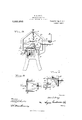
- Figure 1 is a side elevation of the engraving machine of this invention.
- Fig. 2 is a top plan view of the same.
- Fig. 3 is a transverse section of the machine taken on the line83 of Fig. 2.
- Fig. 4 is a side elevation, partly in section of the adjustable block and the gravingpoint supported thereby.
- Fig. 5 is a horizontal sectional view taken through the same.
- Fig. 6 is a detail enlarged view in elevation of the adjusting mechanism for the graving-point.
- Fig. 7 is a top plan view of the same.
- Fig. 8 is a longitudinal central section taken through the work carriage, disclosing a plate to be engraved supported therein.
- Fig. 9 is a tranverse section taken centrally through the same.
- Fig. 10 is a detail enlarged plan view of the composing stick.
- Fig. 11 is a central transverse section taken through the pattern table, the composing stick and the pattern bar in position as disclosed in Fig. 2.
- Fig. 12 is a detail enlarged longitudinal sectional view through one of the stops employed in connection with the composingstick.
- Figs. 13 and 14 are enlarged details of one of the clamps employed.
- ings, 1O designates a frame upon which is mountedthe improved mechanism.
- This frame 10 may be of any adaptable construc.
- the frame has an upper horizontal portion its upper edge a longitudinal downwardly facing rack bar 12 with which engages a pinion 13 fixed'upon the stem of a handf wheel 1 -1, the stem being rotatably mounted in the lower end of a lug 15 depending from the carriage 11 against the outerside of the rack bar 12.
- a bracket. 16 depends from the carriage 11 betweenthe rails of the frame and has its lower end extending laterally beneath the rail 10 in which lowerend is carried a set screw 17 1novable against a clamping plate 18 loose uponthebracket 16 in position'to engage the lower edge of the rail 10 to bind the carriage 11 from movement'upon the tightening of the set screw 17.
- a recess 19 is provided which is relatively wide and located near the outer end of the carriage leaving a transverse flange 20 across such end.
- a set screw 21 is carried through the flange 20 and adapted to bind blocks, plates, and the like to be engraved in the recess 19 against the opposite wall thereof.
- the inner portion of the plate constituting the carriage 11 has a central longitudinal dovetail groove 22 in its upper face opening throughout its length into a longitudinal recess 23 of greater width than the groove but of less depth than the same.
- a dove-tail block '24 is slidably fitted in the groove 22 and carries upon its upper face a spring tongue 25, the latter being movable in the recess 23.
- the screw-threaded shank of a handle 26 engages through the tongue 25 and into the block 24, the handle 26 being adapted to be turned into the block to bind the tongue against the block and interlock the same in the groove and recess.
- the tongue 25 is given a slight curve lon gitudinally and is slightly beveled at its forward end and at its underside for engagement with a plate 27 to be engraved and for binding the plate down upon the carriage 11.
- a retaining strip 28 is secured transversely across the upper face of the plate or carriage 11 and slightly overhangs athe' recess23, and is adapted to engage one edge of the plate to be engraved.
- the tongue 25 presses the plate 27 against the retaining strip 28.
- the frame 10 is provided with a yoke 29, the same constituting a flanged casting suit- .ably bolted or riveted to the outer end of the 'frame, the yoke extending up vertically from the frame.
- a bar 30 is disposed hori- .zonta-lly within the yoke and carries an adjustable upwardly extending cone-bearing screw'31 intermediate its ends.
- Pivotally mounted upon the cone-bearing 31 is a sleeve 32 provided with an upstanding post 33 re- :ceiving in its upperend a downwardly extending cone-bearing screw 3%. This sleeve 532 is adapted to support the pantograph of this machine.
- the pantograph comprises a supporting lever 35 slidable through the sleeve 32 and being clamped therein in adjusted posit-ion by a set screw 36 extending through the sleeveand engaging the supporting lever 35.
- the lever. 35 is adapted to swing laterally with the sleeve.
- aguiding arm 37 Arranged for movement in parallelisnrwith the supporting lever 35 is .
- the connecting link 38 has hinged or'pivotal connection with the inner end of the supporting lever 35 and has hinged connection with the guiding arm 37 at a point adjacent the outer end of the same.
- the connecting lever 39 has hinged connection with the outer end of the guiding arm 37 and with the supportinglever 35 at a point spaced from the inner end of the supporting lever 35 a distance equal to the distance between the hinged connections of the levers 38 and 39 with the guiding arm 37.
- This system of levers or arms constitutes the body of the :pantograph.
- the supporting lever 35 being adjustable longitudinally through the sleeve 32, is provided'with a suitable scale 40 cooperating with afixed line, or other indication upon the sleeve relative to which the scale 40 upon the lever 35 is adapted to be adjusted.
- a carrying block A]. is slidably mounted upon the connecting lever 39 and depends therefrom, the block being movable longitudinally upon the connecting lever 39 and with respect to a scale 42 fixed upon the lever 39.
- the scale as is provided with certain indications the spaces between which consecutively decrease in such proportions as has been found necessary in the practical use of the machine in order to effect the engraving of the letters or designs in a straight line relative to the pattern table, and with respect to the height of the letters or designs engraved.
- the indications or marks upon the scale 42 are given similar characters of reference, 3, 4, 5, 6, etc., extending from the end of the scale adjacent the supporting lever 35 outwardly toward the guiding arm 37.
- the scales and 42 are found to bear a certain relation with respect to one another to such an extent that if the supporting lever 35 be moved inwardly to the point 4, disclosed in Fig. 2 of the drawings, it will be necessary to move the carrying block 41 outwardly along the scale 42 until the fixed indication upon the carrying block registers with the indication designated as 4 upon the scale 42.
- the carrying block 41 is provided with a suitable set screw 43 adapted to bind the block in position upon the connecting lever 39 when the block is adjusted.
- the block 41 is of hollow construction and is provided in its upper and lower portions with arms 44 and 45 suitably hinged in the block and extendin inwardly toward the supporting lever 35.
- the outer ends of the arms and 45 are forked and are provided with opposed bearing members pivotally supporting collars 46 secured to the opposite ends of a connecting sleeve 47 supported upon the outer ends of the arms 44 and 45.
- the collars 46 are spaced apart from the sleeve 47 a distance equal to the distance between the pivotal supporting points of the inner ends of the arms 44 and 45 upon the block 41.
- the sleeve 47 carries a graving-point 48 projecting slightly from the lower end of the sleeve and being suitably held in the sleeve by friction, or the like.
- the lower pivoted arm 45 is provided at its inner end with an upstanding finger 49 to which is attached a cord or other flexible member 50 adapted to be drawn taut to rock the finger 49 outwardly from the carrying block 41 and raise the arms 44 and 45 to lift the graying-point from the surface being engraved.
- the outer end of the guiding arm 37 is provided with a grooved roller 51 located immediately beneath the pivotal connecting point of the arm 37 and lever 39 and adapted to receive the cord 50 thereover passing from the carrying block 41.
- the cord 50 extends longitudinally of the guiding arm 37 to the inner end of the same where it passes up- 'wardly over a second grooved roller 52 and has connection with a suitable operating lever 53.
- the operating lever 53 is pivoted intermediate its ends upon the upper end of an ear upwardly extending from the arm 37 inwardly of the grooved roller 52.
- the outer end of the operating lever 53 is provided with a laterally extending pin 55 over which slidably passes the cord 50, the end of the latter being suitably secured beneath a clip 56 of any suitable type.
- the inner end of the operating lever 53 is provided with a hinged thumb latch 57 mounted for lateral movement relative to the vertical movement of the operating lever 53 and having a lip 58 for engagement beneath a stationary dog 59 mounted upon the arm 37.
- this mechanism is disclosed as being in a locked or lifting position wherein the cord 50 is adapted to be so adjusted that the graving-point 48 is lifted clear of the engraving surface when the operating lever 53 is in the position disclosed in Fig. 6.
- the inner end of the guiding arm 37 is provided with a suitable tracing-point 61 adapted to follow the lines of the letters or designs hereinafter fully described.
- a pattern table 62 Across the inner end of the frame 10 is mounted a pattern table 62 supported upon a suitable bracket 63 and comprising a flat bed plate with upstanding flanges at its longitudinal edges.
- a master plate 64 Slidably positioned in this pattern table is a master plate 64 comprising a long flat bar having, in intaglio upon its opposite sides, suitable letters, de-- signs, or any other configurations to be engraved, the master plate being adapted for sliding movement longitudinally in the pattern table to bring any portion thereof into register with various points intermediate the ends of the table.
- the lines upon this master plate are adapted to receive the trac ing-point 61 and guide the pantograph in its movements in operating the gravingpoint 48.
- This invention includes an improved means for quickly determining the spacing of the various letters and designs and the center point of the set-up lines so that the operator may work quickly and accurately with the use of the machine.
- a novel composing stick 65 disclosed in detail in Figs. 10 and 11-wherein the composing stick is formed of a base strip 66 on the upper face of which and. at one lon 'itudinal'edge is positioned a relatively narrow spacing strip 67 supporting upon its upper face an overhanging strip 68 provid ing a groove or channel between the base strip 66 and the strip 68 for the reception of the top edges of a plurality of dummies 69.
- These dummies 69 are made of any suitable material, have imprinted or indicated in any suitable manner upon their upper faces the letters or configurations to be engraved, and are each of a width corresponding to the character of the letter or configuration upon its upper face. These dummies 69 are held in grouped relation with their lateral edges abutting one another by a pair of adjustable stops 7 0. Each stop 7 0 comprises a flat piece of metal extending across the upper face of the overhanging strip 68 and having arlip 71 projecting into the groove between the base strip and the overhanging strip and adapted to rest against the outer edges of the end dummies.
- the composing stick is adapted to receive a number of these dummies 69, which are preferably contained in a tray or the like having pockets dividing the corresponding dummies into separate groups as in the disposition of type to be set, the dummies being placed in the composing stick to provide the words, letters or the like desired.
- dummies comprising the words Mrs. John Doe
- the master plate 64 which is slidable upon the pattern table, is provided with a clamp 72 comprising a strip of metal lying across the upper face of the master plate midway between its ends and having a thumb screw 73 passing down through the strip and engaging in a threaded opening formed through the master plate.
- the thumb screw 73 is provided for the purpose of detachably holding the clamp 72 upon the master plate 6%.
- the outer end of the clamp 72 is provided with a depending pin 74 fitting into an opening in the master plate registering with the pin for the purpose of holding the clamp 72 in the desired position.
- the clamp 72 engages over the inner edge of the pattern table and carries a set screw 75 adapted to bind against the edge of the pattern table and clamp the master plate from movement when once adjusted.
- the composing stick 65 is also slidable lon gitudinally upon the pattern table but adjacent to the forward edge of the same, the master plate 6 and composing stick 65 entirely filling the space between the upstanding parallel flanges at the longitudinal edges of the pattern table. The composing stick adjusted.
- the 65 carries a clamp 76 overlapping the forward'flange of the pattern table and having a set screw 77 engaging the edge of the pattern table to bind the composing stick in position.
- the clamps 7 2 and 77 may be of anyapproved form which will securely hold the movable members when they are once
- the clamps are of the form which is disclosed to advantage in Figs. 13 and let wherein the body of the clamp 72 comprises a flat strip of metal lying horizontally and provided at its outer end with a depending portion through which is threaded the thumb screw 75.
- the horizontal portion of the clamp 72 carries a plate 78 provided at its upper end with a slot loosely receiving the horizontal portion of the clamp, the plate 78 being loose upon the body portion of the clamp and resting againstthe inner end of the thumb screw 7
- the thumb screw 75 is adapted to bind the plate 7 8 against the outer edge of the pattern table 62 for the purpose of drawing the master plate, or the composing stick, as the case may be, against the adjacent flange of the pattern table and bind the master plate or the composing stick in position.
- the composing stick may be made from an integral bar thickened along one edge and provided with an undercut groove into which may be inserted the top edges of the dummies 69.
- the graving-point 4:8 is pressed down upon the surface to be engraved by its own weight, and also by additional weights such as 79.
- the weight 79 may be of any desired thickness or'fo-rm, but preferably as shown is in disk form, having a radial slot in one side extending from the center of the disk to its periphery whereby the weight 79 may be engaged about the sides of the sleeve 47 which constitutes the graver stock.
- the lower collar 46 is formed relatively high and the middle portion of the weight, or that about the marginal edge of the slot in the weight is adapted to rest upon the collar 46 and support the weight a distance above the lower arm 45 sufficient not to interfere with the adjustment of the gravingpoint. In this manner, the weight 79 may be quickly removed from the graver stock, and weights of Various sizes may be substituted therefor, and even a number of weights may be arranged in superposed relation about the graver stock or sleeve d7.
- this engraving machine is substantially as follows: If it is desired to engrave upon the plate 27 the words Mrs. John Doe, it is first necessary to select the corresponding dummies 69fro1n the tray and place the same in the desired positions in the composing stick to spell out or form these words.
- the plate 27 which is to be engraved is placed upon the work carriage 11 having one edge against the strip 28 while its opposite edge is engaged by the forward edge of the spring tongue 25.
- the handle 26 is now screwed down into the block 2% when the tongue is rocked forward slightly and caused to bind against the plate 27, forcing the plate down upon the carriage 11 and securely holding it in place.
- the pantograph is now adjusted to dispose the gravingpoint 48 at the desired position above the plate whereupon the tracingpoint 61 is moved to a point intermediate the ends of the table 62.
- the middle portion of the composing stick is now made coincident with the tracing-point by loosening the clamp 76 and sliding the composing stick over the table 62 until the central portion of the composing stick, or line of dummies adjusted thereon, is brought into register with the tracing-point 61.
- the clamp 76 is now tightened to hold the composing stick from movement.
- the operatoi now adjusts the pantograph in order to obtain letters of the desired height and width to be engraved upon the plate 27.
- the operator moves the supporting lever 35 through the sleeve 32 until the scale indicates a certain desired position.
- the scale indicates a certain desired position.
- the master plate is now adjusted to the pattern table, and the side of the plate having out there-- into the letters of the alphabet, the period, the comma, and various like symbols, is faced upwardly.
- the master plate 64 is now attached to the clamp 72, the plate 64 and the clamp moving together and being adjusted upon the pattern table to the desired positions to bring the letters in the master plate into register with the corree spending letters or the dummies 69.
- the master plate is adjusted for each letter disclosed by the dummies until the entire name or word has been engraved. Since the composing stick 65 is clamped upon the pattern table, each letter assembled upon the composing stick has a position advanced from the preceding letter, and the master plate must be brought into register with the succeeding letters of the composing stick to bring the desired letter of the master plate into proper position relative to the plate 27 being engraved. In tracing the letters or forms of the master plate 64, it is necessary to lift the tracing-point out of the grooves forming the letters and to move the tracing-point to a new position or to a different groove to give the desired stroke or movement to the pantograph.
- the operating lever 53 is utilized for lifting the graving-point 48 out of engagement with the plate 47 so that the pantograph is permitted to carry the graving-point 48 to a new position without cutting into the plate 27.
- the thumb latch 57 extends to a point near the inner extremity of the guiding arm 37 so as to be in a position to be readily engaged by the thumb of the operator to depress the thumb latch 57 and thereby draw taut the cord 50 and swing the arms 44 and 45 up away from the plate 27.
- the thumb latch 57 When the machine is not in use and it is desired to remove the plate 27, the thumb latch 57 may be depressed and swung inwardly to engage the lip 58 with the dog 59 whereby to lock the graying-point 48 in raised position.
- the carriage 11 is movable upon the rails of the main frame for the purpose of bringing the plate 27 to be engrayed into the desired position beneath the graving-point 48 so as to dispose the letters, or the like to be engraved intermediate the edges of the plate 27 or toward the abutment or top thereof.
- the machine is capable of all necessary adjustment, effects a mechanical accuracy in the formation of the engraved letters not capable of being effected by hand, and with considerable rapidity since it is only necessary to ascertain the center points for the graving-point 48 and the tracing-point 61.
- the machine is adapted particularly for simply outlining or framing the letters and designs to be engraved and leaving the cross hatching and shading to hand work by the engraver.
- the master plate may be provided with the cross hatching lines, and shading lines and the machine may be operated to mechanically finish the work. In this latter case, it would only be necessarv to remove the plate 27 and to polish or finish the same with engravers charcoal, or the like, so as to remove the rough marginal edges of the grooves or cuts made by the graving-point.
- a pantograph In an engraving machine, a pantograph, a tool block carried upon one arm of the pantograph, vertically spaced apart and parallel arms hinged at their inner ends upon said block and adapted to swing down by gravity, a vertically disposed graverstock hinged upon the outer ends of said arms, and a graving-point carried in said graver-stock.
- a pantograph a tool block mounted on one arm of the pantograph, vertically spaced apart arms hinged at their inner ends upon the block, a graver-stock hinged upon the outer ends of said arms and adapted to swing-therewith freely in a vertical plane, said arms be ing-disposed in parallel relation with one another whereby to holdthe graver stock vertically at all times.
- a support a pantograph mounted on the support, a scale upon said pantograph indicating the adjust-i ment of the pantograph on'the support,- a
- tool block carried upon onearm of the pan-: tograph, a scale upon the pantograph indi-i eating the relative movement of the block upon the pantograph, a pair of arms hinged upon the block and being vertically spaced apart, a graver-stock hinged upon the outer ends of said arms, said arms being mounted to swing in parallelism into allad-justments, a graving-point mounted in said graver-.
- a pantograph a tracing-point depending from the pantograph, a pattern ta ble extending transversely of the machine beneath the tracing-point, a composing'stick mountedon the pattern table, a pluralityof dummies set up in said composing stick and bearing configurations to be engraved, and a master plate'adjustable on said pattern table and having a plurality of forms to be engravedcut into one side forthe reception of the tracing-point.
- An engraving machine having a pan- "tograph with a tracing-point, a pattern table arranged beneath the tracing-point, a composing stick resting, upon the pattern table, a plurality of dummy-letters set up in the composing stick in any desired arrangement, and a pattern bar adjustable upon the pattern table and having in intaglio in the side thereof the designs adapted to be engraved.
- An engraving machine graph having a tracing-point," a pattern table beneath the tracing-point, a composing-stick mounted on the pattern table, a plurality of dummies suitably arranged in .t-he composing stick and bearing various dejsigns'to be engraved, and a master plate adjustable upon the pattern table and having cut therein patterns to be engraved, said hnaster plate being adapted to be adjusted iupon the'table to bring the separate patterns into register with the corresponding dummies of thecomposing stick whereby to determine the center of said tracing-point.
- a pantograph having a tracingpoint, a pattern table disposed beneath the tracing-point, a composing stick located upon the pattern :table, a. plurality of dummies suitably arrangedin the composing stick, said dummieseach bearing a design to be engraved and being of a size corresponding'to the design, and a pattern bar adjustable i upon the pattern: table and having a plura-lity'of'patterns cut therein corresponding to thedesigns of the dummies,
- a panto-- said pattern bar being adapted to be adjusted to bring the patterns separately into register with the dummies bearing the corresponding designs, said tracing-point being adapted for movement over the patterns.
- a pantograph having a tracingpoint, a pattern bar provided at its longitudinal edges with a pair of upstanding flanges, a composing stick slidably mounted on the pattern bar, a clamp for said oomposing stick engaging one of said flanges to hold the composing stick thereagainst, a plurality of dummies suitably arranged in the composing stick each one of which being provided with a design and being of a size corresponding to the design, stops mounted on the composing stick and adapted to hold said dummies together, a pattern bar slidable on the pattern table, a clamp carried by the pattern bar and engaging the opposite flange whereby to hold said pattern bar against said opposite flange, said pattern bar being provided with a plurality of patterns corresponding to the designs on the dummies, said pattern bar being adapted for adjustment upon the pattern table whereby to bring separately the patterns into register with the corresponding designs and determine the position of the pantograph for each design.
Landscapes
- Treatment Of Fiber Materials (AREA)
Description
R. E. GRAY.
ENGRAVING MACHINE.
APPLICATION FILED 001. 1 a, 1912. I
Patented Aug. 5, 1913.
1,069,652. I 6 SHEETS-SHBET 1.
Q f%-, Q I R g I H mmmmmlfimlm WE O J \HHII'IILUIHHHHHi Ii O H v I P Q 5 a Q" I awm/wtoz (WWW/5m I 770115. ro y COLUMBIA PLANOdR AAAAAAAAAAAAAAAAAAAA c.
Patented Aug. 5, 1913.
6 SHEETSSHEET 3.
COLUMBIA PLANOuRAPI-l 50.. WASHINGTON. D. C.
R. E. GRAY.
ENGRAVING MAGHINE.
APPLICATION FILED 001'. 1B, 1912.
Patented Aug. 5, 1913.
5 SHEETS-SHEET 4.
'IIIIIIIIIIIIIIII v g m E COLUMBIA PLANOGRAPH co., WASHINGTON, n. c.
R. E. GRAY.
ENGRAVING MACHINE.
APPLICATION FILED 0GT.18, 1912.
1,069,652, Patented Aug. 5, 1913.
6 SHEETS-SHEET 5.
2%: 1 Twila/f? COL'UMBIA PLANOGRAPH COQWASHYNGTON, D, c.
'UNTTEE STATES PATENT OFFTQE.
ROSS E. GRAY, OF WASHINGTON, DISTRICT OF COLUMBIA, ASSIGNOR OF ONE-HALF TO W. F. ROBERTS AND ALLEN C. CLARK, BOTH OF WASHINGTON, DISTRICT OF CO- LUMBIA.
ENGRAVING-MACHINE.
Application filed October 18, 1912.
To all whom 2'2. may concern Be it known that 1, Ross E. GRAY, a citi zen of the United States, residing at ashington, in the District of Columbia, have invented new and useful Improvements in Engravingliachines, of which the following is a specification.
This invention relates to engraving machines, and more particularly to machines of the pantographic type, or wherein a combination of arms or levers is used to direct the graving-point from a tracing-point, the latter being moved over and guided by certain patterns or forms.
The machine of this invention is designed to accurately and mechanically outline in their proper positions the letters or forms to be engraved so that the relative spacing of the forms or letters will be exact and uniform proportionately to the height of the letters or forms. By this machine the finishing of the engraved letters may be made by hand so that the particular style and characteristics of the engraver may be incorporated in the finished work. The patterns or forms of the letters may be provided with cross hatching and other finishing lines so that the machine will mechanically finish the work, and wherein it will be only necessary to scrape and polish the engraved sur face with engravers charcoal, or the like, to remove the roughness produced by the graving-point.
A very important and novel feature of this invention is in providing a pattern table and peculiar devices for setting up the pattern and determining the relative positions of the letters and forms with respect to the surface to be engraved. Broadly, this feature of the invention contemplates a pattern bar having intaglio patterns or forms in its face and which may be adjusted to bring any portion of the bar into register with the desired portion of the machine, and to provide a composing stick carrying a number of dummies bearing letters or forms and being of a size corresponding relatively to the letters or forms thereon.
In engraving machines up to the present time there has been found the difficulty of overcoming the irregularities in the depth and angle of the cut or groove in the engraving surface formed by the graving-point-. The difliculty is due to the fact that the Specification of Letters Patent.
Patented Aug. 5,1913.
Serial No. 726,431.
graving-point is mounted for vertical position in a certain adjustment of the machine, butv the graving-point will not remain in a true vertical position upon any slight up or down adjustment of the point incident to the thickness of the plate, or any irregularities in the surface of the same.
This invention designs, among its objects, to overcome this difliculty by peculiarly mounting the graving-point so that it will lie at all times in a true vertical position and will cut a uniform groove in the surface engraved irrespective of any up or down adjustments of the machine or of any irregularities in the surface to be engraved. This feature of the invention is accomplished by the provision of an adjustable carrying block or member associated with the pantograph, and which carries vertically spaced pivoted members in the outer ends of which is mounted in a vertical position the graving-point. These pivoted members are adapted to hold the graving-point in a true vertical position at all adjustments of the graving-point so that a uniform groove will be cut in the engraved surface.
Various other important objects and advantages of this invention will appear from the following specification and drawings set ting forth one embodiment of this invention.
In the drawings: Figure 1 is a side elevation of the engraving machine of this invention. Fig. 2 is a top plan view of the same. Fig. 3 is a transverse section of the machine taken on the line83 of Fig. 2. Fig. 4 is a side elevation, partly in section of the adjustable block and the gravingpoint supported thereby. Fig. 5 is a horizontal sectional view taken through the same. Fig. 6 is a detail enlarged view in elevation of the adjusting mechanism for the graving-point. Fig. 7 is a top plan view of the same. Fig. 8 is a longitudinal central section taken through the work carriage, disclosing a plate to be engraved supported therein. Fig. 9 is a tranverse section taken centrally through the same. Fig. 10 is a detail enlarged plan view of the composing stick. Fig. 11 is a central transverse section taken through the pattern table, the composing stick and the pattern bar in position as disclosed in Fig. 2. Fig. 12 is a detail enlarged longitudinal sectional view through one of the stops employed in connection with the composingstick. Figs. 13 and 14: are enlarged details of one of the clamps employed.
Referring to the drawings, inwhich like reference characters indicate similar parts throughout the several views of the draw-.
ings, 1O designates a frame upon which is mountedthe improved mechanism. This frame 10 may be of any adaptable construc.
tion, but preferably as shown, wherein the frame has an upper horizontal portion its upper edge a longitudinal downwardly facing rack bar 12 with which engages a pinion 13 fixed'upon the stem of a handf wheel 1 -1, the stem being rotatably mounted in the lower end of a lug 15 depending from the carriage 11 against the outerside of the rack bar 12. A bracket. 16 depends from the carriage 11 betweenthe rails of the frame and has its lower end extending laterally beneath the rail 10 in which lowerend is carried a set screw 17 1novable against a clamping plate 18 loose uponthebracket 16 in position'to engage the lower edge of the rail 10 to bind the carriage 11 from movement'upon the tightening of the set screw 17.
In the upper face of the carriage 11 a recess 19 is provided which is relatively wide and located near the outer end of the carriage leaving a transverse flange 20 across such end. A set screw 21 is carried through the flange 20 and adapted to bind blocks, plates, and the like to be engraved in the recess 19 against the opposite wall thereof. The inner portion of the plate constituting the carriage 11 has a central longitudinal dovetail groove 22 in its upper face opening throughout its length into a longitudinal recess 23 of greater width than the groove but of less depth than the same. A dove-tail block '24 is slidably fitted in the groove 22 and carries upon its upper face a spring tongue 25, the latter being movable in the recess 23. The screw-threaded shank of a handle 26 engages through the tongue 25 and into the block 24, the handle 26 being adapted to be turned into the block to bind the tongue against the block and interlock the same in the groove and recess. The tongue 25 is given a slight curve lon gitudinally and is slightly beveled at its forward end and at its underside for engagement with a plate 27 to be engraved and for binding the plate down upon the carriage 11. A retaining strip 28 is secured transversely across the upper face of the plate or carriage 11 and slightly overhangs athe' recess23, and is adapted to engage one edge of the plate to be engraved. The tongue 25 presses the plate 27 against the retaining strip 28.
The frame 10 is provided with a yoke 29, the same constituting a flanged casting suit- .ably bolted or riveted to the outer end of the 'frame, the yoke extending up vertically from the frame. A bar 30 is disposed hori- .zonta-lly within the yoke and carries an adjustable upwardly extending cone-bearing screw'31 intermediate its ends. Pivotally mounted upon the cone-bearing 31 is a sleeve 32 provided with an upstanding post 33 re- :ceiving in its upperend a downwardly extending cone-bearing screw 3%. This sleeve 532 is adapted to support the pantograph of this machine.
The pantograph comprises a supporting lever 35 slidable through the sleeve 32 and being clamped therein in adjusted posit-ion by a set screw 36 extending through the sleeveand engaging the supporting lever 35. iThe lever. 35 is adapted to swing laterally with the sleeve. Arranged for movement in parallelisnrwith the supporting lever 35 is .aguiding arm 37, the latter being offset rearwardly from the supporting lever 35 and having connection with the same through the connecting links 38 and 39. The connecting link 38 has hinged or'pivotal connection with the inner end of the supporting lever 35 and has hinged connection with the guiding arm 37 at a point adjacent the outer end of the same. The connecting lever 39 has hinged connection with the outer end of the guiding arm 37 and with the supportinglever 35 at a point spaced from the inner end of the supporting lever 35 a distance equal to the distance between the hinged connections of the levers 38 and 39 with the guiding arm 37. This system of levers or arms constitutes the body of the :pantograph. The supporting lever 35, being adjustable longitudinally through the sleeve 32, is provided'with a suitable scale 40 cooperating with afixed line, or other indication upon the sleeve relative to which the scale 40 upon the lever 35 is adapted to be adjusted. The various indications upon the scale 40 are given the numbers 3, A, 5, 6, etc, beginning at the inner end of the scale and running out toward the end of the same, the indications being equidistantly spaced apart. A carrying block A]. is slidably mounted upon the connecting lever 39 and depends therefrom, the block being movable longitudinally upon the connecting lever 39 and with respect to a scale 42 fixed upon the lever 39. The scale as is provided with certain indications the spaces between which consecutively decrease in such proportions as has been found necessary in the practical use of the machine in order to effect the engraving of the letters or designs in a straight line relative to the pattern table, and with respect to the height of the letters or designs engraved. The indications or marks upon the scale 42 are given similar characters of reference, 3, 4, 5, 6, etc., extending from the end of the scale adjacent the supporting lever 35 outwardly toward the guiding arm 37. The scales and 42 are found to bear a certain relation with respect to one another to such an extent that if the supporting lever 35 be moved inwardly to the point 4, disclosed in Fig. 2 of the drawings, it will be necessary to move the carrying block 41 outwardly along the scale 42 until the fixed indication upon the carrying block registers with the indication designated as 4 upon the scale 42. The carrying block 41 is provided with a suitable set screw 43 adapted to bind the block in position upon the connecting lever 39 when the block is adjusted.
Referring particularly to Figs. 4 and 5 of the drawings, the block 41 is of hollow construction and is provided in its upper and lower portions with arms 44 and 45 suitably hinged in the block and extendin inwardly toward the supporting lever 35. The outer ends of the arms and 45 are forked and are provided with opposed bearing members pivotally supporting collars 46 secured to the opposite ends of a connecting sleeve 47 supported upon the outer ends of the arms 44 and 45. The collars 46 are spaced apart from the sleeve 47 a distance equal to the distance between the pivotal supporting points of the inner ends of the arms 44 and 45 upon the block 41. This arrangement maintains a true parallelism between the arms 44 and 45 at all adjustments of the sleeve 47, as is clearly disclosed in the full and dotted lines of Fig. 4. The sleeve 47 carries a graving-point 48 projecting slightly from the lower end of the sleeve and being suitably held in the sleeve by friction, or the like. The lower pivoted arm 45 is provided at its inner end with an upstanding finger 49 to which is attached a cord or other flexible member 50 adapted to be drawn taut to rock the finger 49 outwardly from the carrying block 41 and raise the arms 44 and 45 to lift the graying-point from the surface being engraved. The outer end of the guiding arm 37 is provided with a grooved roller 51 located immediately beneath the pivotal connecting point of the arm 37 and lever 39 and adapted to receive the cord 50 thereover passing from the carrying block 41. The cord 50 extends longitudinally of the guiding arm 37 to the inner end of the same where it passes up- 'wardly over a second grooved roller 52 and has connection with a suitable operating lever 53. The operating lever 53 is pivoted intermediate its ends upon the upper end of an ear upwardly extending from the arm 37 inwardly of the grooved roller 52. The outer end of the operating lever 53 is provided with a laterally extending pin 55 over which slidably passes the cord 50, the end of the latter being suitably secured beneath a clip 56 of any suitable type. The inner end of the operating lever 53 is provided with a hinged thumb latch 57 mounted for lateral movement relative to the vertical movement of the operating lever 53 and having a lip 58 for engagement beneath a stationary dog 59 mounted upon the arm 37. In Fig. 6 this mechanism is disclosed as being in a locked or lifting position wherein the cord 50 is adapted to be so adjusted that the graving-point 48 is lifted clear of the engraving surface when the operating lever 53 is in the position disclosed in Fig. 6. It is not desired to hold the graving-point 48 in a raised position at all times, and it has been found by practice to be inconvenient to provide an automatic locking mechanism for the lever 53, and with this end in view the operating lever 53 is provided with a light spring 60 of leaf-form placed against the inner side of the lever 53 and bearing at its free end against the inner side of the thumb latch 57,- whereby to normally hold the thumb latch 54 out of the path of the dog 59.
The inner end of the guiding arm 37 is provided with a suitable tracing-point 61 adapted to follow the lines of the letters or designs hereinafter fully described.
Across the inner end of the frame 10 is mounted a pattern table 62 supported upon a suitable bracket 63 and comprising a flat bed plate with upstanding flanges at its longitudinal edges. Slidably positioned in this pattern table is a master plate 64 comprising a long flat bar having, in intaglio upon its opposite sides, suitable letters, de-- signs, or any other configurations to be engraved, the master plate being adapted for sliding movement longitudinally in the pattern table to bring any portion thereof into register with various points intermediate the ends of the table. The lines upon this master plate are adapted to receive the trac ing-point 61 and guide the pantograph in its movements in operating the gravingpoint 48.
This invention includes an improved means for quickly determining the spacing of the various letters and designs and the center point of the set-up lines so that the operator may work quickly and accurately with the use of the machine. For carrying out this feature of the invention, there is provided a novel composing stick 65, disclosed in detail in Figs. 10 and 11-wherein the composing stick is formed of a base strip 66 on the upper face of which and. at one lon 'itudinal'edge is positioned a relatively narrow spacing strip 67 supporting upon its upper face an overhanging strip 68 provid ing a groove or channel between the base strip 66 and the strip 68 for the reception of the top edges of a plurality of dummies 69. These dummies 69 are made of any suitable material, have imprinted or indicated in any suitable manner upon their upper faces the letters or configurations to be engraved, and are each of a width corresponding to the character of the letter or configuration upon its upper face. These dummies 69 are held in grouped relation with their lateral edges abutting one another by a pair of adjustable stops 7 0. Each stop 7 0 comprises a flat piece of metal extending across the upper face of the overhanging strip 68 and having arlip 71 projecting into the groove between the base strip and the overhanging strip and adapted to rest against the outer edges of the end dummies.
The composing stick is adapted to receive a number of these dummies 69, which are preferably contained in a tray or the like having pockets dividing the corresponding dummies into separate groups as in the disposition of type to be set, the dummies being placed in the composing stick to provide the words, letters or the like desired. In Fig. 2 of the drawings the composing stick is provided with dummies comprising the words Mrs. John Doe By close observation of the drawings it will be noted that each letter, period, and space is indicated upon or by a separate dummy 69. The master plate 64, which is slidable upon the pattern table, is provided with a clamp 72 comprising a strip of metal lying across the upper face of the master plate midway between its ends and having a thumb screw 73 passing down through the strip and engaging in a threaded opening formed through the master plate. The thumb screw 73 is provided for the purpose of detachably holding the clamp 72 upon the master plate 6%. The outer end of the clamp 72 is provided with a depending pin 74 fitting into an opening in the master plate registering with the pin for the purpose of holding the clamp 72 in the desired position. The clamp 72 engages over the inner edge of the pattern table and carries a set screw 75 adapted to bind against the edge of the pattern table and clamp the master plate from movement when once adjusted. The composing stick 65 is also slidable lon gitudinally upon the pattern table but adjacent to the forward edge of the same, the master plate 6 and composing stick 65 entirely filling the space between the upstanding parallel flanges at the longitudinal edges of the pattern table. The composing stick adjusted.
65 carries a clamp 76 overlapping the forward'flange of the pattern table and having a set screw 77 engaging the edge of the pattern table to bind the composing stick in position. The clamps 7 2 and 77 may be of anyapproved form which will securely hold the movable members when they are once Preferably, the clamps are of the form which is disclosed to advantage in Figs. 13 and let wherein the body of the clamp 72 comprises a flat strip of metal lying horizontally and provided at its outer end with a depending portion through which is threaded the thumb screw 75. The horizontal portion of the clamp 72 carries a plate 78 provided at its upper end with a slot loosely receiving the horizontal portion of the clamp, the plate 78 being loose upon the body portion of the clamp and resting againstthe inner end of the thumb screw 7 The thumb screw 75 is adapted to bind the plate 7 8 against the outer edge of the pattern table 62 for the purpose of drawing the master plate, or the composing stick, as the case may be, against the adjacent flange of the pattern table and bind the master plate or the composing stick in position. It will be understood that the composing stick may be made from an integral bar thickened along one edge and provided with an undercut groove into which may be inserted the top edges of the dummies 69.
The graving-point 4:8 is pressed down upon the surface to be engraved by its own weight, and also by additional weights such as 79. The weight 79 may be of any desired thickness or'fo-rm, but preferably as shown is in disk form, having a radial slot in one side extending from the center of the disk to its periphery whereby the weight 79 may be engaged about the sides of the sleeve 47 which constitutes the graver stock. The lower collar 46 is formed relatively high and the middle portion of the weight, or that about the marginal edge of the slot in the weight is adapted to rest upon the collar 46 and support the weight a distance above the lower arm 45 sufficient not to interfere with the adjustment of the gravingpoint. In this manner, the weight 79 may be quickly removed from the graver stock, and weights of Various sizes may be substituted therefor, and even a number of weights may be arranged in superposed relation about the graver stock or sleeve d7.
The operation and adjustment of this engraving machine is substantially as follows: If it is desired to engrave upon the plate 27 the words Mrs. John Doe, it is first necessary to select the corresponding dummies 69fro1n the tray and place the same in the desired positions in the composing stick to spell out or form these words. The plate 27 which is to be engraved is placed upon the work carriage 11 having one edge against the strip 28 while its opposite edge is engaged by the forward edge of the spring tongue 25. The handle 26 is now screwed down into the block 2% when the tongue is rocked forward slightly and caused to bind against the plate 27, forcing the plate down upon the carriage 11 and securely holding it in place. The pantograph is now adjusted to dispose the gravingpoint 48 at the desired position above the plate whereupon the tracingpoint 61 is moved to a point intermediate the ends of the table 62. The middle portion of the composing stick is now made coincident with the tracing-point by loosening the clamp 76 and sliding the composing stick over the table 62 until the central portion of the composing stick, or line of dummies adjusted thereon, is brought into register with the tracing-point 61. The clamp 76 is now tightened to hold the composing stick from movement. The operatoi now adjusts the pantograph in order to obtain letters of the desired height and width to be engraved upon the plate 27. To this end, the operator moves the supporting lever 35 through the sleeve 32 until the scale indicates a certain desired position. In order to effect the movement of the supporting block 41 across the plate 27 in a true straight line parallel with the composing stick, it is necessary to adjust the block 41 to a corresponding point or indication upon the scale. on the connecting lever 39. The master plate is now adjusted to the pattern table, and the side of the plate having out there-- into the letters of the alphabet, the period, the comma, and various like symbols, is faced upwardly. The master plate 64 is now attached to the clamp 72, the plate 64 and the clamp moving together and being adjusted upon the pattern table to the desired positions to bring the letters in the master plate into register with the corree spending letters or the dummies 69. In this manner the master plate is adjusted for each letter disclosed by the dummies until the entire name or word has been engraved. Since the composing stick 65 is clamped upon the pattern table, each letter assembled upon the composing stick has a position advanced from the preceding letter, and the master plate must be brought into register with the succeeding letters of the composing stick to bring the desired letter of the master plate into proper position relative to the plate 27 being engraved. In tracing the letters or forms of the master plate 64, it is necessary to lift the tracing-point out of the grooves forming the letters and to move the tracing-point to a new position or to a different groove to give the desired stroke or movement to the pantograph. In adjusting the tracing-point 61 in this manner, the operating lever 53 is utilized for lifting the graving-point 48 out of engagement with the plate 47 so that the pantograph is permitted to carry the graving-point 48 to a new position without cutting into the plate 27. The thumb latch 57 extends to a point near the inner extremity of the guiding arm 37 so as to be in a position to be readily engaged by the thumb of the operator to depress the thumb latch 57 and thereby draw taut the cord 50 and swing the arms 44 and 45 up away from the plate 27.
When the machine is not in use and it is desired to remove the plate 27, the thumb latch 57 may be depressed and swung inwardly to engage the lip 58 with the dog 59 whereby to lock the graying-point 48 in raised position. The carriage 11 is movable upon the rails of the main frame for the purpose of bringing the plate 27 to be engrayed into the desired position beneath the graving-point 48 so as to dispose the letters, or the like to be engraved intermediate the edges of the plate 27 or toward the abutment or top thereof. It is thus seen that the machine is capable of all necessary adjustment, effects a mechanical accuracy in the formation of the engraved letters not capable of being effected by hand, and with considerable rapidity since it is only necessary to ascertain the center points for the graving-point 48 and the tracing-point 61.
The machine is adapted particularly for simply outlining or framing the letters and designs to be engraved and leaving the cross hatching and shading to hand work by the engraver. However, it is readily seen that the master plate may be provided with the cross hatching lines, and shading lines and the machine may be operated to mechanically finish the work. In this latter case, it would only be necessarv to remove the plate 27 and to polish or finish the same with engravers charcoal, or the like, so as to remove the rough marginal edges of the grooves or cuts made by the graving-point.
It will, of course, be understood that many modifications may be made to the structure herein disclosed since this is but one embodiment of the invent-ion and is specincally described simply for the purpose of disclosing the principles of the invention, all of the changes made being subject to the limitations of the following claims.
IVhat I claim is:
1. In an engraving machine, a pantograph, a tool block carried upon one arm of the pantograph, vertically spaced apart and parallel arms hinged at their inner ends upon said block and adapted to swing down by gravity, a vertically disposed graverstock hinged upon the outer ends of said arms, and a graving-point carried in said graver-stock.
2. In an engraving machine, a pantograph, a tool block mounted on one arm of the pantograph, vertically spaced apart arms hinged at their inner ends upon the block, a graver-stock hinged upon the outer ends of said arms and adapted to swing-therewith freely in a vertical plane, said arms be ing-disposed in parallel relation with one another whereby to holdthe graver stock vertically at all times.
3. In an engraving machine, the comb-ination with a movable carrying member, means for moving the member, and I a gravingpoint, of a pair of parallel arms hinged upon said member and having hinged connection with said graving-point whereby to: hold said point parallel in all planes of adjustment, said arms and said graving point being adapted to swing freely in a vertical plane.
4. In an engraving machine, th'e combination with a frame, of a work support on the frame, a pantographon the frame adjustable relative to the work' support, agraving= point adjust-able on one of the arms of the pantograph, and means indicating the relative adjustment of said adjustable parts whereby to produce characters differing in: size.
5. In an engraving machine, the combination with a frame, of an adjustable worki support on the frame, a panto-graph adjust-' ably mounted on the frame, a carrying block! adjustable on one of the arms of the pantograph, and a graving-point hinged upon the block whereby the point is held 'inxa true vertical position in all adjustments.
6. In an engraving machine, the-'combinm tion with a pantograph', of an adjustable block mounted upon one arm offthe panto-i graph, a pair of parallel vertically spaced: arms hinged upon the block, a graver-stockl hinged adjacent its ends upon the outer ends of said arms, agraving-point mounted in: said stock, and means mounted'upon the pantograph and having connection with-one of said arms adapted to swing said arms up-: wardly in parallelism and raisexsaid .grav-' ing-point.
7. In an engraving machine, a support, a pantograph mounted on the support, a scale upon said pantograph indicating the adjust-i ment of the pantograph on'the support,- a
tool block carried upon onearm of the pan-: tograph, a scale upon the pantograph indi-i eating the relative movement of the block upon the pantograph, a pair of arms hinged upon the block and being vertically spaced apart, a graver-stock hinged upon the outer ends of said arms, said arms being mounted to swing in parallelism into allad-justments, a graving-point mounted in said graver-. stock, a finger projecting upwardly from the innerend of one of said arms, anda COI'dt attached to said fingerand extendingfto the free end of saidpantograph whereby*the cord is adapted to be drawn taut to raise said arms and graving-point- 8': In an engraving machine, a pantograph, an adjustable block on the pantograph, parallel arms-hinged at their inner ends upon the block, a graving-point sup ported upon the outer ends of the arms, a finger upstanding-from the inner end of one of the arms, a cord attached to the upper end of'said finger, an operating'lever mounted upon the free end of the pantograph and having connection with the opposite end of the cord, a thumb latch carried upon theoperating lever and adapted to swing the same to draw said cord taut whereby to raise said arms and said graving-point, and means mounted upon the pantograph forlocking said operating lever in position to hold said graying-point raised.
9. In an engraving machine, and in combination, a pantograph, a tracing-point depending from the pantograph, a pattern ta ble extending transversely of the machine beneath the tracing-point, a composing'stick mountedon the pattern table, a pluralityof dummies set up in said composing stick and bearing configurations to be engraved, and a master plate'adjustable on said pattern table and having a plurality of forms to be engravedcut into one side forthe reception of the tracing-point.
10. An engraving machinehaving a pan- "tograph with a tracing-point, a pattern table arranged beneath the tracing-point, a composing stick resting, upon the pattern table, a plurality of dummy-letters set up in the composing stick in any desired arrangement, and a pattern bar adjustable upon the pattern table and having in intaglio in the side thereof the designs adapted to be engraved. I 11. An engraving machine, graph having a tracing-point," a pattern table beneath the tracing-point, a composing-stick mounted on the pattern table, a plurality of dummies suitably arranged in .t-he composing stick and bearing various dejsigns'to be engraved, and a master plate adjustable upon the pattern table and having cut therein patterns to be engraved, said hnaster plate being adapted to be adjusted iupon the'table to bring the separate patterns into register with the corresponding dummies of thecomposing stick whereby to determine the center of said tracing-point.
' 12 In an engraving machine, andin combination,.a pantograph having a tracingpoint, a pattern table disposed beneath the tracing-point, a composing stick located upon the pattern :table, a. plurality of dummies suitably arrangedin the composing stick, said dummieseach bearing a design to be engraved and being of a size corresponding'to the design, and a pattern bar adjustable i upon the pattern: table and having a plura-lity'of'patterns cut therein corresponding to thedesigns of the dummies,
a panto-- said pattern bar being adapted to be adjusted to bring the patterns separately into register with the dummies bearing the corresponding designs, said tracing-point being adapted for movement over the patterns.
13. In an engraving machine, and in combination, a pantograph having a tracingpoint, a pattern bar provided at its longitudinal edges with a pair of upstanding flanges, a composing stick slidably mounted on the pattern bar, a clamp for said oomposing stick engaging one of said flanges to hold the composing stick thereagainst, a plurality of dummies suitably arranged in the composing stick each one of which being provided with a design and being of a size corresponding to the design, stops mounted on the composing stick and adapted to hold said dummies together, a pattern bar slidable on the pattern table, a clamp carried by the pattern bar and engaging the opposite flange whereby to hold said pattern bar against said opposite flange, said pattern bar being provided with a plurality of patterns corresponding to the designs on the dummies, said pattern bar being adapted for adjustment upon the pattern table whereby to bring separately the patterns into register with the corresponding designs and determine the position of the pantograph for each design.
In testimony whereof I have hereunto set my hand in presence of two subscribing witnesses.
ROSS E. GRAY. Vitnesses:
GERTRUDE M. STUGKER,
C. H. FEsLEn.
Copies of this patent may be obtained for five cents each, by addressing the Commissioner of Patents, Washington, D. C.
Priority Applications (1)
| Application Number | Priority Date | Filing Date | Title |
|---|---|---|---|
| US72643112A US1069652A (en) | 1912-10-18 | 1912-10-18 | Engraving-machine. |
Applications Claiming Priority (1)
| Application Number | Priority Date | Filing Date | Title |
|---|---|---|---|
| US72643112A US1069652A (en) | 1912-10-18 | 1912-10-18 | Engraving-machine. |
Publications (1)
| Publication Number | Publication Date |
|---|---|
| US1069652A true US1069652A (en) | 1913-08-05 |
Family
ID=3137889
Family Applications (1)
| Application Number | Title | Priority Date | Filing Date |
|---|---|---|---|
| US72643112A Expired - Lifetime US1069652A (en) | 1912-10-18 | 1912-10-18 | Engraving-machine. |
Country Status (1)
| Country | Link |
|---|---|
| US (1) | US1069652A (en) |
Cited By (1)
| Publication number | Priority date | Publication date | Assignee | Title |
|---|---|---|---|---|
| US2627658A (en) * | 1947-04-03 | 1953-02-10 | Edwin T Green | Engraving machine |
-
1912
- 1912-10-18 US US72643112A patent/US1069652A/en not_active Expired - Lifetime
Cited By (1)
| Publication number | Priority date | Publication date | Assignee | Title |
|---|---|---|---|---|
| US2627658A (en) * | 1947-04-03 | 1953-02-10 | Edwin T Green | Engraving machine |
Similar Documents
| Publication | Publication Date | Title |
|---|---|---|
| US1069652A (en) | Engraving-machine. | |
| US1229111A (en) | Pantographic apparatus. | |
| US1139984A (en) | Imposing-table and proof-press. | |
| US790172A (en) | Tracing apparatus. | |
| US1235668A (en) | Pantographic engraving-machine. | |
| US731066A (en) | Molding-knife protractor. | |
| US895944A (en) | Punching-machine. | |
| US435243A (en) | District | |
| US1667028A (en) | Material-working apparatus | |
| US1068478A (en) | Apparatus for cutting matrices. | |
| US962439A (en) | Engraving-machine. | |
| US238882A (en) | Engraving-machine | |
| US1014012A (en) | Pantograph. | |
| US784633A (en) | Duplicating defect-tracer. | |
| US575532A (en) | Book-finishing machine | |
| US2426156A (en) | Type assembly | |
| US1228990A (en) | Saw leveling and stretching machine. | |
| US3263333A (en) | Circular template for engraving machines and the like | |
| US1912707A (en) | Printing face forming apparatus | |
| US539544A (en) | Engraving-machine | |
| US1288083A (en) | Lumber-marking device. | |
| US1625062A (en) | Engraving machine | |
| US99794A (en) | Improvement in engraving-machines | |
| US1776347A (en) | Attachment for composing-room saws | |
| US496489A (en) | Island |