US10696415B2 - Propulsion unit for an aircraft, with reduced aerodynamic drag - Google Patents
Propulsion unit for an aircraft, with reduced aerodynamic drag Download PDFInfo
- Publication number
- US10696415B2 US10696415B2 US16/222,266 US201816222266A US10696415B2 US 10696415 B2 US10696415 B2 US 10696415B2 US 201816222266 A US201816222266 A US 201816222266A US 10696415 B2 US10696415 B2 US 10696415B2
- Authority
- US
- United States
- Prior art keywords
- nacelle
- turbojet engine
- lower beam
- air flow
- aircraft
- Prior art date
- Legal status (The legal status is an assumption and is not a legal conclusion. Google has not performed a legal analysis and makes no representation as to the accuracy of the status listed.)
- Active
Links
- 238000011144 upstream manufacturing Methods 0.000 claims description 5
- 238000001816 cooling Methods 0.000 description 4
- 238000002485 combustion reaction Methods 0.000 description 3
- 241000499489 Castor canadensis Species 0.000 description 1
- 235000011779 Menyanthes trifoliata Nutrition 0.000 description 1
- 230000005540 biological transmission Effects 0.000 description 1
- 238000005516 engineering process Methods 0.000 description 1
- 238000004519 manufacturing process Methods 0.000 description 1
- 238000012986 modification Methods 0.000 description 1
- 230000004048 modification Effects 0.000 description 1
- 238000011084 recovery Methods 0.000 description 1
- 239000000126 substance Substances 0.000 description 1
Images


Classifications
-
- B—PERFORMING OPERATIONS; TRANSPORTING
- B64—AIRCRAFT; AVIATION; COSMONAUTICS
- B64D—EQUIPMENT FOR FITTING IN OR TO AIRCRAFT; FLIGHT SUITS; PARACHUTES; ARRANGEMENT OR MOUNTING OF POWER PLANTS OR PROPULSION TRANSMISSIONS IN AIRCRAFT
- B64D29/00—Power-plant nacelles, fairings or cowlings
- B64D29/06—Attaching of nacelles, fairings or cowlings
-
- B—PERFORMING OPERATIONS; TRANSPORTING
- B64—AIRCRAFT; AVIATION; COSMONAUTICS
- B64D—EQUIPMENT FOR FITTING IN OR TO AIRCRAFT; FLIGHT SUITS; PARACHUTES; ARRANGEMENT OR MOUNTING OF POWER PLANTS OR PROPULSION TRANSMISSIONS IN AIRCRAFT
- B64D27/00—Arrangement or mounting of power plants in aircraft; Aircraft characterised by the type or position of power plants
- B64D27/02—Aircraft characterised by the type or position of power plants
- B64D27/16—Aircraft characterised by the type or position of power plants of jet type
- B64D27/18—Aircraft characterised by the type or position of power plants of jet type within, or attached to, wings
Definitions
- the present disclosure relates to the field of turbojet engine nacelles for an aircraft with a high bypass ratio.
- An aircraft is moved by several turbojet engines each housed within a nacelle.
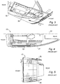
- the propulsion unit constituted by a turbojet engine and the nacelle that receives it is shown in FIG. 1 referred thereto.
- the propulsion unit 1 comprises a nacelle 3 supporting a turbojet engine 5 .
- the propulsion unit 1 is connected to the aircraft fuselage (not shown) for example by means of a pylon 7 intended to be suspended under a wing of the aircraft.
- the nacelle 5 generally has a tubular structure comprising an upstream section 9 defining an air inlet upstream of the turbojet engine 5 , a median section 11 intended to surround a fan of the turbojet engine, a downstream section 13 comprising an outer cowling 15 able to accommodate a thrust reverser device and intended to surround the combustion chamber of the turbojet engine, and is generally terminated by an ejection nozzle whose outlet is located downstream of the turbojet engine.
- This nacelle accommodates the turbojet engine 5 which can be of the bypass type, adapted to generate, via the blades of the rotating fan, a hot air flow (also called primary flow), coming from the combustion chamber of the turbojet engine, and a cold air flow (secondary flow) that circulates outside the turbojet engine through a flow path 17 (half-flow path 17 a shown in FIG. 2 ), also called annular channel, formed between a fairing of the turbojet engine and an inner wall 18 (inner half-wall 18 a shown in FIG. 2 ) of the outer structure 21 (outer half-structure 21 a shown in FIG. 2 ) of the nacelle.
- the two air flows are ejected from the turbojet engine from the rear of the nacelle.
- FIG. 2 showing a right half-shell 13 a of a nacelle that constitutes, with a second half-shell (not represented, obtained by symmetry relative to a median plane of the nacelle), the downstream structure 13 of the nacelle able to surround the combustion chamber of the turbojet engine (not represented in this figure).
- this downstream structure can integrate a thrust reversal device, on the understanding that the invention also applies to a smooth nacelle case, that is to say devoid of a thrust reversal device.
- the references FRONT and REAR respectively designate the front (upstream) and rear (downstream) portions of the half-shell 13 a , relative to the direction of the air flow intended to circulate inside this half-shell 13 a.
- this half-shell 13 a includes an inner half-structure 19 a , defining a half-cavity C intended to receive the turbojet engine (not represented).
- An inner structure 19 is obtained by the assembly of two inner half-structures 19 a and 19 b (only the half-structure 19 a is shown in FIG. 2 , the half-structure 19 b being positioned symmetrically with the half-structure 19 a relative to the median plane of the nacelle).
- This half-shell 13 a also includes an outer structure 21 a defining, with the inner half-structure 19 a , a half-flow path 17 a intended to be traversed by a cold air flow circulating between the front and the back of the half-shell 13 a and defining, with the half-flow path obtained by symmetry relative to the median plane of the nacelle, the flow path 17 or annular channel.
- connection of the engine to the aircraft is carried out by means of a support structure comprising two upper longitudinal half-beams 23 a , 23 b (only the half-beam 23 a is shown in FIG. 2 , the half-beam 23 b being positioned symmetrically with the half-beam 23 a relative to the median plane of the nacelle), conventionally called 12 o'clock beams because of their position at the top of the nacelle and two lower longitudinal half-beams 25 a , 25 b (only the half-beam 25 a is shown in FIG.
- the half-beam 25 b being positioned symmetrically with the half-beam 25 a relative to the median plane of the nacelle), conventionally called 6 o'clock beams because of their position in the lower portion of the nacelle.
- the lower “6 o'clock” half-beams 25 a , 25 b are conventionally faired by means of fairing sheets 26 (represented in FIG. 3 showing the nacelle 3 viewed from the bottom) intended to come into contact with the outer air flow flowing around the nacelle.
- the 12 o'clock and 6 o'clock half-beams are interconnected, on the one hand, via the inner structure 19 surrounding the turbojet engine and, on the other hand, via a substantially annular structure called front frame and generally formed of two front half-frames 27 a , 27 b (only the front half-frame 27 a is shown in FIG. 2 , the front half-frame 27 b being positioned symmetrically with the front half-frame 27 a relative to the median plane of the nacelle) each extending between said corresponding half-beams on both side of the median plane of the nacelle.
- This front frame is intended to be fixed to the periphery of a downstream edge of a casing of the fan engine and thus contribute to the recovery and transmission of forces between the different portions of the nacelle and of the turbojet engine. Furthermore, in the case of a nacelle equipped with a cascade thrust reverser device, the front frame is also used to support the cascades of the thrust reverser.
- a cascade thrust reverser comprises two half-cowls (forming the outer cowling 15 shown in FIG. 1 ) each slidably mounted on the upper 23 a , 23 b and lower 25 a , 25 b half-beams.
- the upper and lower half-beams are generally equipped with primary and secondary guide rails allowing a sliding movement of the half-cowls of the cascade thrust reverser, on its associated half-beam between alternately a position of the thrust reverser in direct jet according to which the half-cowls ensure the aerodynamic continuity of the nacelle and a position of the thrust reverser in reverse jet according to which the half-cowls are displaced downstream of the nacelle.
- the bypass ratio of a turbojet engine is defined by the ratio between the air mass of the cold air flow passing through the flow path of the propulsion unit and the mass of the hot air flow passing through the turbojet engine.
- a high bypass ratio for example a ratio of 10
- the diameter of the flow path 17 of the cold air flow is increased relative to an engine with a lower bypass ratio.
- the increase in the diameter of the flow path 17 results in a radial distance, relative to the longitudinal axis of the propulsion unit, of the lower “6 o'clock” half-beams 25 a , 25 b.
- the radial distance of the lower half-beams 25 a , 25 b results in a radial distance of the fairing sheets 26 (shown in FIG. 3 illustrating the nacelle viewed from the bottom) fixed on the outer wall of the lower “6 o'clock” half-beams and coming into contact with an outer air flow F ext flowing around the nacelle.
- FIG. 4 illustrating the downstream section 13 of the nacelle in longitudinal section on which there is shown an aerodynamic surface 29 defined by the fairing sheets 26 and an aerodynamic surface 31 that would be obtained when the diameter of the flow path 17 would have been increased in order to obtain an engine with a higher bypass ratio.
- the outer aerodynamic surface 31 of the nacelle has become radially more distant relative to the longitudinal axis 33 of the nacelle and relative to the outer aerodynamic surface 29 obtained for an engine with a lower bypass ratio.
- This increase in the diameter of the nacelle results in an increase in the size and the mass of the nacelle.
- this also directly results in an increase in the size of the “beavertail” or “six o'clock rear beam fairing,” a term used to designate the fairing 35 in the form of a “beaver tail” downstream of the nacelle and shown in FIGS. 3 and 5 .
- the increase in the size and the mass of the nacelle and in the “beavertail” causes an increase in the aerodynamic drag of the nacelle.
- the present disclosure provides a nacelle for an aircraft turbojet engine with a high bypass ratio, having a reduced aerodynamic drag.
- the present disclosure relates to a nacelle for an aircraft turbojet engine, the nacelle comprising:
- said nacelle being remarkable in that an outer wall of the lower beam is designed to define at least partially an outer aerodynamic surface of the nacelle, intended to come into contact with an air flow external to said nacelle, said outer wall of the lower beam being further designed to be tolerant to the damage caused by said outer air flow.
- the aerodynamic fairing sheets present in the prior art are removed. This allows reducing the radial thickness of the lower beam relative to the thickness obtained for a lower beam used in a turbojet engine with equivalent bypass ratio.
- the mass of the nacelle and of the beavertail is reduced, which advantageously allows reducing the aerodynamic drag of the nacelle.
- the removal of the aerodynamic fairing sheets provided in the prior art allows the “6 o'clock” lower beam to be directly in contact with the outer air flow.
- the outer air flow laps the 6 o'clock lower beam, which allows cooling more effectively the lower beam relative to the prior art.
- This is very advantageous because the propulsion unit area in which the 6 o'clock lower beam is located is a hot area of the propulsion unit. Additional cooling means of the beam may not be needed thanks to the present disclosure.
- the outer structure of the nacelle of the present disclosure accommodates thrust reversal device comprising at least one movable thrust reverser cowl, and the lower and upper beams receive guide rails in translation of said movable thrust reverser cowl.
- the lower beam of the nacelle of the present disclosure comprises two half-beams symmetrically distributed relative to a median plane of the nacelle.
- the present disclosure also concerns a propulsion unit for an aircraft, remarkable in that it comprises a nacelle according to the present disclosure and a turbojet engine supported by said nacelle, said turbojet engine having a bypass ratio comprised between 8 and 15.
- FIG. 1 illustrates an isometric view of a propulsion unit according to the prior art
- FIG. 2 represents a half-shell of the downstream section of a nacelle according to the prior art
- FIG. 3 is a bottom view of the nacelle, centered on its downstream section according to the prior art
- FIG. 4 represents the downstream section of the nacelle in a longitudinal section on which the aerodynamic surfaces of the nacelle are represented according to the prior art
- FIG. 5 is a side view of the downstream section of the nacelle according to the prior art.
- FIG. 6 is a bottom view of a nacelle according to the present disclosure, centered on its downstream section.
- the terms “inner” and “outer” are used in a non-limiting manner with reference to the radial distance relative to the longitudinal axis of the nacelle, the expression “inner” defining a zone radially closer to the longitudinal axis of the nacelle, as opposed to the term “outer”.
- a nacelle 100 according to the present disclosure is represented, in a bottom view.
- the nacelle according to the present disclosure differs from that presented with reference to FIGS. 1 to 5 in that the “six o'clock” lower beam 125 has an outer wall 126 designed to define at least partially an outer aerodynamic surface of the nacelle.
- the expression “designed to define at least partially an outer aerodynamic surface of the nacelle” means the characteristic according to which the beam 125 joins the outer aerodynamic surface 139 of the nacelle. In other words, it is directly the outer wall 126 of the lower beam 125 that is intended to come into contact with an outer air flow F ext to said nacelle.
- the lower beam 125 is thus designed to be tolerant to the damage caused by the outer air flow F ext flowing around the nacelle 100 .
- the aerodynamic fairing sheets present in the related art are removed. This allows reducing the radial thickness of the lower beam 125 relative to the thickness obtained for a lower beam of the related art, used in a turbojet engine with an equivalent bypass ratio.
- the mass of the nacelle 125 and of the “beavertail” 135 is thus reduced relative to the related art for a turbojet engine having an equivalent bypass ratio.
- the aerodynamic drag of the nacelle 125 is then reduced.
- the removal of the aerodynamic fairing sheets provided in the related art allows the lower beam 125 to be directly in contact with the outer air flow F ext .
- the outer air flow F ext laps the lower beam 125 , which allows cooling more effectively the lower beam 125 relative to the related art.
- This is very advantageous because the area of the propulsion unit in which the lower beam 125 is located is a hot propulsion unit area. Additional cooling means of the beam may not be needed thanks to the present disclosure.
- the lower beam 125 comprises, like the lower beam 25 of the related art, two lower half-beams 125 a , 125 b symmetrically distributed relative to the median plane of the nacelle.
- Each lower half-beam 125 a , 125 b can receive guide rails in translation of the movable thrust reverser cowl when the downstream section of the nacelle accommodates a thrust reverser device.
- the upper half-beams 23 a , 23 b defining the upper beam 23 then also receive guide rails in translation of the movable thrust reverser cowl.
- the present disclosure is intended to be implemented, for example, on small-sized nacelles, that is to say nacelles having an air input diameter in the order of 180 centimeters.
- this size is only given as an indication and the present disclosure can quite be implemented on nacelles of different sizes, having a diameter in particular comprised between 100 cm and 300 cm.
- the present disclosure also concerns a propulsion unit comprising a nacelle according to the present disclosure supporting a turbojet engine having a bypass ratio, for example, between 8 and 15.
- nacelle and propulsion unit described above is for illustrative purposes only and the present disclosure is not limited to the nacelle and the propulsion unit described above, but instead all the variants involving the technical equivalents of the means described and their combinations fall within the scope of the present disclosure.
- the phrase at least one of A, B, and C should be construed to mean a logical (A OR B OR C), using a non-exclusive logical OR, and should not be construed to mean “at least one of A, at least one of B, and at least one of C.
Landscapes
- Engineering & Computer Science (AREA)
- Aviation & Aerospace Engineering (AREA)
- Structures Of Non-Positive Displacement Pumps (AREA)
Applications Claiming Priority (4)
| Application Number | Priority Date | Filing Date | Title |
|---|---|---|---|
| FR1655684A FR3052746B1 (fr) | 2016-06-17 | 2016-06-17 | Ensemble propulsif pour aeronef, a trainee aerodynamique reduite |
| FR1655684 | 2016-06-17 | ||
| FR16/55684 | 2016-06-17 | ||
| PCT/FR2017/051508 WO2017216463A1 (fr) | 2016-06-17 | 2017-06-13 | Ensemble propulsif pour aéronef à traînée aérodynamique réduite |
Related Parent Applications (1)
| Application Number | Title | Priority Date | Filing Date |
|---|---|---|---|
| PCT/FR2017/051508 Continuation WO2017216463A1 (fr) | 2016-06-17 | 2017-06-13 | Ensemble propulsif pour aéronef à traînée aérodynamique réduite |
Publications (2)
| Publication Number | Publication Date |
|---|---|
| US20190202574A1 US20190202574A1 (en) | 2019-07-04 |
| US10696415B2 true US10696415B2 (en) | 2020-06-30 |
Family
ID=57137019
Family Applications (1)
| Application Number | Title | Priority Date | Filing Date |
|---|---|---|---|
| US16/222,266 Active US10696415B2 (en) | 2016-06-17 | 2018-12-17 | Propulsion unit for an aircraft, with reduced aerodynamic drag |
Country Status (4)
| Country | Link |
|---|---|
| US (1) | US10696415B2 (fr) |
| EP (1) | EP3472049A1 (fr) |
| FR (1) | FR3052746B1 (fr) |
| WO (1) | WO2017216463A1 (fr) |
Families Citing this family (1)
| Publication number | Priority date | Publication date | Assignee | Title |
|---|---|---|---|---|
| CN116674758B (zh) * | 2022-04-28 | 2024-05-24 | 中国航发沈阳发动机研究所 | 一种非接触式飞发搭接结构设计方法 |
Citations (2)
| Publication number | Priority date | Publication date | Assignee | Title |
|---|---|---|---|---|
| EP1092859A1 (fr) | 1999-10-14 | 2001-04-18 | Hispano-Suiza Aérostructures | Inverseur de poussée de turboréacteur |
| EP2690273A2 (fr) * | 2012-07-24 | 2014-01-29 | Christian Soria | Rail intégré d'inverseur de poussée et structure interne fixe |
Family Cites Families (2)
| Publication number | Priority date | Publication date | Assignee | Title |
|---|---|---|---|---|
| US5369954A (en) * | 1991-04-22 | 1994-12-06 | General Electric Company | Turbofan engine bypass and exhaust system |
| EP3055541B1 (fr) * | 2013-10-07 | 2021-12-08 | Rohr, Inc. | Structure fixe interne hybride à construction métallique et composite |
-
2016
- 2016-06-17 FR FR1655684A patent/FR3052746B1/fr active Active
-
2017
- 2017-06-13 WO PCT/FR2017/051508 patent/WO2017216463A1/fr unknown
- 2017-06-13 EP EP17736987.3A patent/EP3472049A1/fr not_active Ceased
-
2018
- 2018-12-17 US US16/222,266 patent/US10696415B2/en active Active
Patent Citations (2)
| Publication number | Priority date | Publication date | Assignee | Title |
|---|---|---|---|---|
| EP1092859A1 (fr) | 1999-10-14 | 2001-04-18 | Hispano-Suiza Aérostructures | Inverseur de poussée de turboréacteur |
| EP2690273A2 (fr) * | 2012-07-24 | 2014-01-29 | Christian Soria | Rail intégré d'inverseur de poussée et structure interne fixe |
Non-Patent Citations (1)
| Title |
|---|
| International Search Report for international patent application PCT/FR2017/051508, dated Aug. 28, 2017. |
Also Published As
| Publication number | Publication date |
|---|---|
| US20190202574A1 (en) | 2019-07-04 |
| FR3052746A1 (fr) | 2017-12-22 |
| EP3472049A1 (fr) | 2019-04-24 |
| FR3052746B1 (fr) | 2019-05-03 |
| WO2017216463A1 (fr) | 2017-12-21 |
Similar Documents
| Publication | Publication Date | Title |
|---|---|---|
| US8726634B2 (en) | Nacelle for an aircraft engine with variable cross-section nozzle having a rack and pinion actuator assembly | |
| US10641206B2 (en) | Nacelle rear assembly for a turbojet engine comprising a cradle for a core-type mast | |
| EP1726812B1 (fr) | Système d'inversion de poussée pour un avion | |
| US10184426B2 (en) | Thrust reverser with forward positioned blocker doors | |
| EP2863038B1 (fr) | Rampe de soufflante d'un inverseur de poussée avec poche pour une porte de blocage | |
| US10605196B2 (en) | Door-type thrust reverser device for aircraft turbojet engine nacelle | |
| US11486332B2 (en) | Aircraft jet engine nacelle, propulsion assembly and aircraft comprising such a nacelle | |
| US11313323B2 (en) | Propulsion unit for aircraft comprising an assembly box-type structure in the six o'clock position | |
| US9856826B2 (en) | Nacelle rear assembly for a turbojet engine comprising a suspension cradle | |
| US10696415B2 (en) | Propulsion unit for an aircraft, with reduced aerodynamic drag | |
| US20150107222A1 (en) | Thrust reverser fan ramp partially formed on aft end of fan case | |
| US20150108248A1 (en) | Thrust reverser fan ramp with noise suppression | |
| US11549462B2 (en) | Turbojet engine nacelle including a single movable frame of a cascade thrust reverser and passages of ancillaries | |
| US20090217643A1 (en) | Gas discharge device for a vehicle engine | |
| US20160208738A1 (en) | Turbojet engine nacelle comprising a unit assembly capable of moving along a guide assembly | |
| CA2935049C (fr) | Aeration de compartiment principal de bord de trainee d'un moteur d'aeronef | |
| US11619191B2 (en) | Bypass propulsion unit, comprising a thrust reverser with movable cascades | |
| US20170009704A1 (en) | Thrust reverser staggered translating sleeve | |
| US11454194B2 (en) | Nacelle for turbojet engine, comprising openings of front cowls for access to fixing points of the nacelle | |
| US10677193B2 (en) | Rear frame for a thrust reverser structure with diversion grids | |
| US20140271169A1 (en) | Nacelle for a high bypass ratio engine with multiple flow paths | |
| US11338930B2 (en) | Aircraft engine nacelle | |
| US12103694B2 (en) | Nacelle air intake and nacelle comprising such an air intake | |
| US10689125B2 (en) | Nacelle for an aircraft turbojet engine with hybrid air inlet and fan cowl | |
| US11047262B2 (en) | Aircraft propulsion system comprising an internal fixed structure with a discharge slot |
Legal Events
| Date | Code | Title | Description |
|---|---|---|---|
| FEPP | Fee payment procedure |
Free format text: ENTITY STATUS SET TO UNDISCOUNTED (ORIGINAL EVENT CODE: BIG.); ENTITY STATUS OF PATENT OWNER: LARGE ENTITY |
|
| AS | Assignment |
Owner name: SAFRAN NACELLES, FRANCE Free format text: ASSIGNMENT OF ASSIGNORS INTEREST;ASSIGNOR:LONCLE, ALEXIS;REEL/FRAME:048669/0669 Effective date: 20180926 |
|
| STPP | Information on status: patent application and granting procedure in general |
Free format text: NON FINAL ACTION MAILED |
|
| STPP | Information on status: patent application and granting procedure in general |
Free format text: RESPONSE TO NON-FINAL OFFICE ACTION ENTERED AND FORWARDED TO EXAMINER |
|
| STPP | Information on status: patent application and granting procedure in general |
Free format text: FINAL REJECTION MAILED |
|
| STPP | Information on status: patent application and granting procedure in general |
Free format text: NOTICE OF ALLOWANCE MAILED -- APPLICATION RECEIVED IN OFFICE OF PUBLICATIONS |
|
| STCF | Information on status: patent grant |
Free format text: PATENTED CASE |
|
| MAFP | Maintenance fee payment |
Free format text: PAYMENT OF MAINTENANCE FEE, 4TH YEAR, LARGE ENTITY (ORIGINAL EVENT CODE: M1551); ENTITY STATUS OF PATENT OWNER: LARGE ENTITY Year of fee payment: 4 |