US10695897B2 - Fluid container diffuser system and related method of use - Google Patents
Fluid container diffuser system and related method of use Download PDFInfo
- Publication number
- US10695897B2 US10695897B2 US15/379,294 US201615379294A US10695897B2 US 10695897 B2 US10695897 B2 US 10695897B2 US 201615379294 A US201615379294 A US 201615379294A US 10695897 B2 US10695897 B2 US 10695897B2
- Authority
- US
- United States
- Prior art keywords
- segment
- tool
- cartridge
- diffuser cartridge
- diffuser
- Prior art date
- Legal status (The legal status is an assumption and is not a legal conclusion. Google has not performed a legal analysis and makes no representation as to the accuracy of the status listed.)
- Active, expires
Links
Images


Classifications
-
- B—PERFORMING OPERATIONS; TRANSPORTING
- B25—HAND TOOLS; PORTABLE POWER-DRIVEN TOOLS; MANIPULATORS
- B25B—TOOLS OR BENCH DEVICES NOT OTHERWISE PROVIDED FOR, FOR FASTENING, CONNECTING, DISENGAGING, OR HOLDING
- B25B27/00—Hand tools, specially adapted for fitting together or separating parts or objects whether or not involving some deformation, not otherwise provided for
- B25B27/02—Hand tools, specially adapted for fitting together or separating parts or objects whether or not involving some deformation, not otherwise provided for for connecting objects by press fit or detaching same
-
- B—PERFORMING OPERATIONS; TRANSPORTING
- B25—HAND TOOLS; PORTABLE POWER-DRIVEN TOOLS; MANIPULATORS
- B25B—TOOLS OR BENCH DEVICES NOT OTHERWISE PROVIDED FOR, FOR FASTENING, CONNECTING, DISENGAGING, OR HOLDING
- B25B13/00—Spanners; Wrenches
- B25B13/02—Spanners; Wrenches with rigid jaws
- B25B13/06—Spanners; Wrenches with rigid jaws of socket type
-
- A—HUMAN NECESSITIES
- A23—FOODS OR FOODSTUFFS; TREATMENT THEREOF, NOT COVERED BY OTHER CLASSES
- A23L—FOODS, FOODSTUFFS OR NON-ALCOHOLIC BEVERAGES, NOT OTHERWISE PROVIDED FOR; PREPARATION OR TREATMENT THEREOF
- A23L2/00—Non-alcoholic beverages; Dry compositions or concentrates therefor; Preparation or treatment thereof
- A23L2/52—Adding ingredients
-
- A—HUMAN NECESSITIES
- A61—MEDICAL OR VETERINARY SCIENCE; HYGIENE
- A61L—METHODS OR APPARATUS FOR STERILISING MATERIALS OR OBJECTS IN GENERAL; DISINFECTION, STERILISATION OR DEODORISATION OF AIR; CHEMICAL ASPECTS OF BANDAGES, DRESSINGS, ABSORBENT PADS OR SURGICAL ARTICLES; MATERIALS FOR BANDAGES, DRESSINGS, ABSORBENT PADS OR SURGICAL ARTICLES
- A61L9/00—Disinfection, sterilisation or deodorisation of air
- A61L9/015—Disinfection, sterilisation or deodorisation of air using gaseous or vaporous substances, e.g. ozone
-
- B—PERFORMING OPERATIONS; TRANSPORTING
- B25—HAND TOOLS; PORTABLE POWER-DRIVEN TOOLS; MANIPULATORS
- B25B—TOOLS OR BENCH DEVICES NOT OTHERWISE PROVIDED FOR, FOR FASTENING, CONNECTING, DISENGAGING, OR HOLDING
- B25B13/00—Spanners; Wrenches
- B25B13/48—Spanners; Wrenches for special purposes
- B25B13/481—Spanners; Wrenches for special purposes for operating in areas having limited access
-
- B—PERFORMING OPERATIONS; TRANSPORTING
- B25—HAND TOOLS; PORTABLE POWER-DRIVEN TOOLS; MANIPULATORS
- B25B—TOOLS OR BENCH DEVICES NOT OTHERWISE PROVIDED FOR, FOR FASTENING, CONNECTING, DISENGAGING, OR HOLDING
- B25B23/00—Details of, or accessories for, spanners, wrenches, screwdrivers
- B25B23/0007—Connections or joints between tool parts
- B25B23/0021—Prolongations interposed between handle and tool
-
- B—PERFORMING OPERATIONS; TRANSPORTING
- B25—HAND TOOLS; PORTABLE POWER-DRIVEN TOOLS; MANIPULATORS
- B25B—TOOLS OR BENCH DEVICES NOT OTHERWISE PROVIDED FOR, FOR FASTENING, CONNECTING, DISENGAGING, OR HOLDING
- B25B27/00—Hand tools, specially adapted for fitting together or separating parts or objects whether or not involving some deformation, not otherwise provided for
- B25B27/14—Hand tools, specially adapted for fitting together or separating parts or objects whether or not involving some deformation, not otherwise provided for for assembling objects other than by press fit or detaching same
-
- C—CHEMISTRY; METALLURGY
- C02—TREATMENT OF WATER, WASTE WATER, SEWAGE, OR SLUDGE
- C02F—TREATMENT OF WATER, WASTE WATER, SEWAGE, OR SLUDGE
- C02F1/00—Treatment of water, waste water, or sewage
- C02F1/68—Treatment of water, waste water, or sewage by addition of specified substances, e.g. trace elements, for ameliorating potable water
- C02F1/685—Devices for dosing the additives
- C02F1/688—Devices in which the water progressively dissolves a solid compound
-
- A—HUMAN NECESSITIES
- A61—MEDICAL OR VETERINARY SCIENCE; HYGIENE
- A61L—METHODS OR APPARATUS FOR STERILISING MATERIALS OR OBJECTS IN GENERAL; DISINFECTION, STERILISATION OR DEODORISATION OF AIR; CHEMICAL ASPECTS OF BANDAGES, DRESSINGS, ABSORBENT PADS OR SURGICAL ARTICLES; MATERIALS FOR BANDAGES, DRESSINGS, ABSORBENT PADS OR SURGICAL ARTICLES
- A61L2209/00—Aspects relating to disinfection, sterilisation or deodorisation of air
- A61L2209/10—Apparatus features
- A61L2209/13—Dispensing or storing means for active compounds
- A61L2209/133—Replaceable cartridges, refills
-
- C—CHEMISTRY; METALLURGY
- C02—TREATMENT OF WATER, WASTE WATER, SEWAGE, OR SLUDGE
- C02F—TREATMENT OF WATER, WASTE WATER, SEWAGE, OR SLUDGE
- C02F2201/00—Apparatus for treatment of water, waste water or sewage
- C02F2201/002—Construction details of the apparatus
- C02F2201/006—Cartridges
-
- C—CHEMISTRY; METALLURGY
- C02—TREATMENT OF WATER, WASTE WATER, SEWAGE, OR SLUDGE
- C02F—TREATMENT OF WATER, WASTE WATER, SEWAGE, OR SLUDGE
- C02F2307/00—Location of water treatment or water treatment device
- C02F2307/02—Location of water treatment or water treatment device as part of a bottle
Definitions
- the present disclosure relates generally to an extension tool, and more specifically, to an elongate tool adapted to facilitate insertion of a diffuser cartridge into a water bottle.
- Personal hydration includes the need for portable drinking fluid containers and bottles. Because of the sustainability and environmental issues associated with plastic and single use water bottles, consumers are attracted to reusable containers as such as stainless steel water bottles. Also stainless steel bottles can be formed to be free of BPA, lead or other toxins making for a healthier container. In addition, consumers have recognized the health benefits of treated drinking fluids such as alkaline water. In this regard, there is a need in the art for combining the benefits of reusable containers in combination with the easy availability of treated fluids such as alkaline water.
- Alkaline water is understood to be beneficial to health for maintaining physical stability and helping to deal with acid buildup in the body in both healthy individuals and those with conditions that cause acidification of the blood. Alkaline water is said to aid in digestion, neutralize acidity, and to also assist in reducing free radicals. In addition, in most instances, alkaline water has the characteristic of smaller water clusters, and a pH above 7.0 that has also been identified as allowing the body to more easily absorb the water. Generally, alkaline water is obtained by water electrolysis and/or through chemical treatment by mineral agents. In many prior art devices for creating alkaline water, electricity is used in association with an apparatus, or otherwise such devices have complex structures that are not conducive for treating drinkable fluids in a portable manner. A discussion of the types and systems for creating alkaline water are described in Chung, U.S. Publication No. 2007/0221556, published Sep. 27, 2007, the substance of which is incorporated herein by reference.
- Prior art devices also disclose the use of mineral agents in fluid vessels, to allow untreated water to come in contact with the agents to form alkaline water.
- Such prior art devices however include multi-part structures that are not user friendly and may not remain fixed in a vessel, as intended, or otherwise use an undesirable amount of volume within a vessel and do not facilitate the flow of water around the mineral agents.
- fluid vessels are shaped to include a closed end portion and an open end portion formed at a narrow neck of the fluid vessel.
- the narrow configuration of the fluid vessel may make it difficult to insert the structures associated with the mineral agents into the fluid vessel.
- a tool adapted for use with a diffuser cartridge and a fluid container, wherein the tool is adapted to facilitate insertion and removal of the diffuser cartridge to and from the fluid container.
- the diffuser cartridge contains mineral agent beads or other materials which can enhance the quality of fluid contained within the container.
- the tool is adapted for use with the diffuser cartridge and a fluid containment vessel having a base, a retaining wall coupled to the base, and an upper rim, with the base and upper rim defining a vessel height.
- the diffuser cartridge is detachably engageable with the retaining wall to assume a nested configuration.
- the tool includes a bottom segment having a first end portion complimentary in shape to the diffuser cartridge and adapted to be selectively engageable with the diffuser cartridge, and a second end portion having a bottom segment connector.
- the tool further includes an intermediate segment separate from the bottom segment and having a first intermediate connector adapted to engage with the bottom segment connector, and a second intermediate connector.
- the tool additionally comprises a top segment separate from the bottom segment and intermediate segment, with the top segment having a top segment connector adapted to engage with the second intermediate connector.
- the intermediate segment is connected to the bottom segment and the top segment when the tool is in an assembled configuration, with the tool being sized and configured such that an end surface of the diffuser cartridge and a portion of the top segment of the tool collectively define an operating length greater than the vessel height.
- the bottom segment may include a cavity adapted to receive a portion of the diffuser cartridge when the first end portion of the bottom segment is engaged with the diffuser cartridge.
- the bottom segment may also include a channel adapted to receive a portion of the diffuser cartridge to effectuate engagement between the bottom segment and the diffuser cartridge.
- the channel may include an axial segment and a radial segment.
- the top segment may include an enlarged end portion opposite the top segment connector, with the enlarged end portion being sized and configured to be grippable by the user.
- the tool may be sized and configured to extend from the diffuser cartridge and beyond the upper rim of the fluid containment vessel when the first end portion is engaged with the diffuser cartridge.
- the bottom segment, intermediate segment and top segment may be formed from a plastic material.
- the intermediate segment and portions of the top and bottom segments may each define an outer diameter substantially equal to each other.
- the tool may be formed of a plurality of interconnectable elements, which when connected, define a length that is long enough to allow the user to insert or remove the diffuser cartridge from the fluid container while the user's hand remains outside of the container. As such, the user is not required to squeeze his or her hand through the narrowing opening commonly associated with such fluid containers.
- the tool and the use thereof allows for the attachment of the diffuser to the bottom of the vessel without the need to have a mechanism for accessing or opening the bottom of the vessel. Adapting a fluid vessel to have a bottom opening increases cost of manufacture and increases the complexity of use, among other issues.
- having the diffuser located at the bottom of the vessel aids in increasing the amount of contact of diffuser ingredients will have with the liquid, as opposed to situating the diffuser in the container lid, for example, where liquid may not contact a diffuser when the container is less than completely full.
- FIG. 1 is an upper perspective view of a container including a vessel body and a cap;
- FIG. 2 is an upper perspective, partial cutaway, exploded view of a diffuser cartridge adapted to be nested within a retaining wall located within the vessel body;
- FIG. 3 is an upper perspective view of the diffuser cartridge
- FIG. 4 is a lower perspective view of the diffuser cartridge
- FIG. 5 is a front cross sectional view of a bottom portion of the vessel body, with the diffuser cartridge being nested within the retaining wall, a portion of the diffuser cartridge being cutaway to reveal mineral beads within the diffuser cartridge;
- FIG. 5A is a front cross sectional view of another embodiment of a bottom portion of the vessel body, and a diffuser cartridge, with the diffuser cartridge being nested within a retaining wall;
- FIGS. 5B and 5C are partial and completely exploded views, respectively, of the embodiment depicted in FIG. 5A ;
- FIG. 6 is an upper perspective, assembled view of a tool adapted for insertion and removal of the diffuser cartridge to and from the vessel;
- FIG. 7 is an upper perspective, exploded view of the tool shown in FIG. 6 ;
- FIG. 8 is an upper perspective, partial cutaway view showing the tool engaged with the diffuser cartridge, with the diffuser cartridge being engaged with the vessel body;
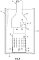
- FIGS. 9-11 show a sequence of connecting the tool to the diffuser cartridge, and removing the diffuser cartridge from the vessel using the tool.
- FIGS. 12-23 show various views of one particular embodiment of the tool.
- a fluid containment vessel e.g., container 10 including a vessel body 12 and a cap 14 operatively engageable with the vessel body 12 .
- the vessel body 12 is formed from an elongate stainless steel sidewall 16 and a base 18 , with the sidewall 18 being tapered at a neck portion 20 adapted to interface with the cap 14 .
- the neck portion 20 terminates at an upper rim 21 , with the vessel body 12 having a first height H 1 (see FIG. 8 ) equal to the distance between the base 18 and the upper rim 21 .
- a user can selectively open and close the container 10 by securing the cap 14 to the vessel body 12 at the neck portion 20 .
- An o-ring may be employed on the cap 14 to assist in forming a fluid tight seal when the cap 14 is placed on the vessel body 14 to close the container 10 .
- the sidewall 16 is disposed about a central axis 22 , with the neck portion 20 providing an opening for which fluid can be inserted or extracted from the vessel body 12 and is wide enough to promote drinking directly from the vessel body 12 .
- a portion of the sidewall 16 may be covered by a gripping pad to enhance the grippability thereof.
- the sidewall 16 may be a single wall or a double wall, with the double wall configuration being employed to enhance the insulating characteristics of the vessel body 12 .
- an insulating material or substance may be disposed between the double walls.
- a diffuser cartridge 24 is detachably affixable/engageable to the base 18 and is adapted to having mineral agent beads 26 (see FIG. 5 ) or other materials that can interact with and treat a fluid contained within the vessel body 12 .
- the mineral agent beads 26 are secured within the cartridge 24 so as not to escape from the cartridge 24 and into the void of the vessel body 12 .
- the exemplary cartridge 24 is of a cylindrical shape, although those skilled in the art will readily appreciate that the cartridge 24 may take on other shapes including, but not limited to a spherical shape, a cuboid shape, or any other shapes.
- the cartridge 24 includes a plurality of perforations 28 formed therein, with the perforations 28 being sized relative to the mineral beads 26 so as to retain the mineral beads 26 within the cartridge 24 , while at the same time allowing the beads 26 to be bathed within the water/fluid contained within the vessel body 12 .
- the perforations 28 shown in the drawings are arranged in rows and columns, although the perforations 28 may be formed on the cartridge 24 in any arrangement or pattern.
- the cartridge 24 depicted in the Figures is a two-part assembly, with an upper body 25 and a lower body 27 that engages with the upper body 25 . The two-part construction of the cartridge 24 facilitates insertion of the filtering beads 26 during manufacture of the cartridge 24 .
- the lower body 27 includes an end wall having the perforations formed therein, and an annular wall extending from the end wall and engaging with the upper body 25 .
- the upper body 25 include an open end portion which receives the lower body 27 , with the upper body 25 having a slightly reduced diameter adjacent the open end portion so as to engage with and retain the lower body 27 .
- the perforations 28 formed on the exemplary cartridge are formed in both the upper and lower bodies 25 , 27 .
- the cartridge 24 defines an outer diameter preferably between 0.5-2.0 inches, and more preferably equal to approximately 1.125 inches.
- the height of the cartridge 24 is preferably between 1.0-3.0 inches, and more preferably equal to approximately 1.6875 inches.
- the cartridge 24 is adapted to engage with a retaining wall 30 , which extends around a retaining cavity 32 and is coupled to the base 18 of the container 10 .
- the retaining wall 30 and corresponding retaining cavity 32 are complimentary in shape to the cartridge 24 to allow the cartridge 24 to be selectively nested within the retaining cavity 32 and engaged with the retaining wall 30 to affix the cartridge 24 to the vessel body 12 .
- the cartridge 24 and the retaining wall 30 are configured to become sufficiently engaged with each other when the cartridge 24 is nested within the retaining cavity 32 so as to hold the cartridge 24 in the nested position as the user repeatedly tips the vessel body 12 to drink the water contained therein.
- the cartridge 24 and the retaining wall 30 may be adapted to create such engagement via a friction-tight fit, spring-type tabs 33 , locking rims, etc.
- FIG. 5 is a cross sectional view of a lower portion of the container 10 showing the cartridge 24 engaged with the raining wall 30 .
- the retaining wall 30 includes an annular portion 31 and a bottom plate 35 , with the annular portion 31 extending upwardly from the bottom plate 35 .
- the bottom plate 35 is connected to the base 18 of the vessel body 12 in direct flat-to-flat engagement. That is to say, a bottom planar surface of the bottom plate 35 is placed in opposed relation to a planar surface of the base 18 .
- the bottom plate 35 may be attached to the base 18 via welding, an adhesive, or other mechanical joining techniques known by those skilled in the art.
- FIGS. 5A-5C there is depicted an alternative embodiment of the lower portion of the container 110 .
- a vessel body 112 is shown having a base 118 which differs slightly from the base 18 shown in FIG. 5 .
- the base 118 includes rounded transition with sidewall 116 , whereas in the embodiment depicted in FIG. 5 , the transition between the base 18 and sidewall 16 is square.
- the container 110 further includes a retaining wall 130 including an annular portion 131 and a bottom section 135 .
- the bottom section 135 includes a plurality of nubs or protuberances 137 extending from a bottom plate 139 , with the nubs/protuberances 137 providing a structure to which the base 118 may be spot welded or otherwise coupled.
- the entire bottom section 135 is not in flat-to-flat engagement with the base 118 , and in fact, the bottom plate 139 may be spaced from the base 118 when the nubs/protuberances 137 are coupled to the base 118 .
- the container 110 further includes cartridge 124 which slightly differs from cartridge 24 discussed above.
- cartridge 124 includes an upper body 125 and a lower body 127 .
- the primary distinction between the cartridge 124 shown in FIGS. 5A-C relative to the cartridge 24 shown in FIG. 5 is that the lower body 127 is inverted relative to the lower body 27 .
- the lower body 127 includes an end wall 129 that is located within the upper body 125 , with the lower body 127 including an annular wall 133 extending from the end wall 129 toward a terminal edge of the upper body 125 adjacent the open end portion of the upper body 125 when the lower body 127 is engaged with the upper body 125 .
- Such engagement between the upper and lower bodies 125 , 127 may be facilitated through press-fit engagement, or through the use of other mechanical fastening mechanisms, including but not limited to adhesives, fasteners or the like.
- the tool 34 is elongate and is formed from a plurality of separate tool elements, including a bottom element 36 , and intermediate element 38 , and a top element 40 .
- the tool 34 is configured such that the tool 34 may be manually manipulated or held by an individual to insert or remove the diffuser cartridge 24 to or from the vessel body 12 , with the tool 34 being configured to allow an individual's hand to remain outside of the vessel body 12 throughout the insertion or removal process.
- the tool 34 and diffuser cartridge 24 collectively define a height H 2 , which is larger than the height H 1 of the vessel body 12 , which allows a portion of the tool to extend beyond the upper rim 21 of the vessel body 24 when the tool 34 is engaged with the diffuser cartridge 24 , and with the diffuser cartridge 24 nested within the retaining cavity 32 .
- the bottom element 36 includes a first end portion 42 adapted to interface with the diffuser cartridge 24 and a second end portion 44 adapted to interface with the intermediate element 38 .
- the first end portion 42 includes a cylindrical wall disposed about a cavity, with the cylindrical wall terminating at a distal end 46 .
- the cavity is adapted to receive the diffuser cartridge 24 , with the inner diameter of the cylindrical wall being slightly larger than the outer diameter of the diffuser cartridge 24 .
- a pair of diametrically opposed cutouts 48 extend into the cylindrical wall from the distal end 46 , with each cutout having an axial segment 50 and a radial segment 52 .
- the axial segment 50 extends from the distal end 46 and the radial segment 52 is spaced from the distal end 46 .
- the dimension of the cutouts 48 corresponds to a pair of diametrically opposed nubs or protrusions 54 formed on the diffuser cartridge 24 .
- the cutouts 48 are configured such that each nub 54 may be received within a respective cutout 48 to operatively couple the bottom element 36 to the diffuser cartridge 24 .
- the second end portion 44 is connected to the first end portion 42 via an intermediate elongate segment 56 , which has a smaller diameter than the cylindrical wall of the first end portion 42 .
- the second end portion 44 includes a male connector wall 58 having an outer diameter smaller than the diameter of the intermediate elongate segment 56 .
- a pair of diametrically opposed locking tabs 60 extend radially outward from the male connector wall 58 . According to one embodiment, each locking tab 60 extends radially outward by a distance equal to one-half of the difference between the diameter of the intermediate elongate segment 56 and the diameter of the male connector wall 58 .
- the intermediate element 38 includes a first end portion 62 and a second end portion 64 and an intermediate segment 66 disposed therebetween.
- the first end portion 62 is adapted to interface with the bottom element 36 and the second end portion 64 is adapted to interface with the top element 40 .
- the first end portion 62 defines a female-type connector adapted to engage with the male-type connector of the bottom element 36
- the second end portion 64 defines a male-type connector adapted to engage with a female-type connector on the top element 40 .
- the first end portion 62 defines a cylindrical wall having a pair of diametrically opposed cutouts 68 extending into the cylindrical wall from a distal end 70 .
- Each cutout 68 includes an axial segment and a radial segment.
- the cutouts 68 are sized and configured to enable the locking tabs 60 of the bottom element 36 to extend therein for coupling the bottom element 36 to the intermediate element 38 .
- the cylindrical wall of the first end portion 62 transitions to the intermediate segment 66 , with the outer diameter of the cylindrical wall being the same as the outer diameter of the intermediate segment 66 .
- the second end portion 64 includes a male connector wall 72 having an outer diameter smaller than the diameter of the intermediate elongate segment 66 .
- a pair of diametrically opposed locking tabs 74 extend radially outward from the male connector wall 72 .
- each locking tab 74 extends radially outward by a distance equal to one-half of the difference between the diameter of the intermediate segment 66 and the diameter of the male connector wall 72 .
- the top element 40 includes a first end portion 76 and a second end portion 78 .
- the first end portion 76 defines a cylindrical wall having a pair of diametrically opposed cutouts 80 extending into the cylindrical wall from a distal end 82 .
- Each cutout 80 includes an axial segment and a radial segment.
- the cutouts 80 are sized and configured to enable the locking tabs 74 of the intermediate element 38 to extend therein for coupling the intermediate element 38 to the top element 40 .
- the cylindrical wall transitions into the second end portion 78 , which includes an outwardly tapering wall to provide an ergonomically friendly gripping portion.
- a user would first assemble the tool 34 by connecting the first end portion 62 of the intermediate element 38 to the bottom element 36 and the second end portion 64 of the intermediate element 38 to the top element 40 .
- the user attaches the diffuser cartridge 24 to the tool 34 by aligning the cutouts 48 formed on the bottom element 36 with the nubs 54 formed on the diffuser cartridge 24 .
- the user then advances the tool 34 over the cartridge 24 , which causes the nubs 54 to pass through the axial segments 50 of the corresponding cutouts 48 .
- the diffuser cartridge 24 is then inserted into the vessel body 12 by holding the tool 34 at the top element 40 and aligning the diffuser cartridge 24 and bottom element 36 of the tool 34 with the opening of the vessel body 12 .
- the user lowers the tool/cartridge assembly into the vessel body 12 until the diffuser cartridge 24 reaches the retaining wall 30 .
- the user presses/pushes the tool 34 therein until the diffuser cartridge 24 is nested within the retaining cavity 32 .
- the user rotates the tool 34 in a second direction opposite to the first direction, which causes the nubs 54 to retreat back through the radial segments 52 of the cutouts 48 formed in the bottom element 36 .
- the user then lifts the tool 34 , which causes the nubs 54 to retreat through the axial segments 50 , which ultimately allows the tool 34 to become disengaged from the diffuser cartridge 24 .
- the tool 34 is then completely removed from the vessel body 12 , and the user may continue using the vessel body 12 with the diffuser cartridge 24 secured therein.
- the user again assembles the tool 34 , as described above, if the tool 34 is disassembled.
- the assembled tool 34 is then inserted into the vessel body 12 until the bottom element 36 reaches the diffuser cartridge 24 .
- the user then rotates the tool 34 to align the cutouts 48 with the nubs 54 .
- the user presses down to allow the nubs 54 to pass through the axial segment 50 , and then rotates the tool 34 in the first direction to allow the nubs 54 to pass through the radial segment 52 , and ultimately, secure the tool 34 to the diffuser cartridge 24 .
Landscapes
- Engineering & Computer Science (AREA)
- Mechanical Engineering (AREA)
- Chemical & Material Sciences (AREA)
- Health & Medical Sciences (AREA)
- Life Sciences & Earth Sciences (AREA)
- Organic Chemistry (AREA)
- Water Supply & Treatment (AREA)
- Medicinal Chemistry (AREA)
- Hydrology & Water Resources (AREA)
- Environmental & Geological Engineering (AREA)
- Polymers & Plastics (AREA)
- Food Science & Technology (AREA)
- Nutrition Science (AREA)
- General Health & Medical Sciences (AREA)
- Veterinary Medicine (AREA)
- Public Health (AREA)
- Animal Behavior & Ethology (AREA)
- Epidemiology (AREA)
- Water Treatment By Sorption (AREA)
- Thermally Insulated Containers For Foods (AREA)
- Hand Tools For Fitting Together And Separating, Or Other Hand Tools (AREA)
- Details Of Rigid Or Semi-Rigid Containers (AREA)
- Devices And Processes Conducted In The Presence Of Fluids And Solid Particles (AREA)
- Coating Apparatus (AREA)
- Containers Having Bodies Formed In One Piece (AREA)
Abstract
Description
Claims (19)
Priority Applications (6)
| Application Number | Priority Date | Filing Date | Title |
|---|---|---|---|
| US15/379,294 US10695897B2 (en) | 2015-12-18 | 2016-12-14 | Fluid container diffuser system and related method of use |
| PCT/US2016/067029 WO2017106561A1 (en) | 2015-12-18 | 2016-12-15 | Fluid container diffuser system and related method of use |
| JP2018550663A JP7013025B2 (en) | 2015-12-18 | 2016-12-15 | Liquid container diffuser system and related uses |
| GB1810026.3A GB2563504B (en) | 2015-12-18 | 2016-12-15 | Fluid container diffuser system and related method of use |
| CN201680079117.0A CN108472806B (en) | 2015-12-18 | 2016-12-15 | Fluid Container Diffusion System and Related Methods of Use |
| US16/908,405 US11707823B2 (en) | 2015-12-18 | 2020-06-22 | Fluid container diffuser system and related method of use |
Applications Claiming Priority (2)
| Application Number | Priority Date | Filing Date | Title |
|---|---|---|---|
| US201562269534P | 2015-12-18 | 2015-12-18 | |
| US15/379,294 US10695897B2 (en) | 2015-12-18 | 2016-12-14 | Fluid container diffuser system and related method of use |
Related Child Applications (1)
| Application Number | Title | Priority Date | Filing Date |
|---|---|---|---|
| US16/908,405 Continuation US11707823B2 (en) | 2015-12-18 | 2020-06-22 | Fluid container diffuser system and related method of use |
Publications (2)
| Publication Number | Publication Date |
|---|---|
| US20170173769A1 US20170173769A1 (en) | 2017-06-22 |
| US10695897B2 true US10695897B2 (en) | 2020-06-30 |
Family
ID=59057637
Family Applications (2)
| Application Number | Title | Priority Date | Filing Date |
|---|---|---|---|
| US15/379,294 Active 2038-01-26 US10695897B2 (en) | 2015-12-18 | 2016-12-14 | Fluid container diffuser system and related method of use |
| US16/908,405 Active 2037-07-05 US11707823B2 (en) | 2015-12-18 | 2020-06-22 | Fluid container diffuser system and related method of use |
Family Applications After (1)
| Application Number | Title | Priority Date | Filing Date |
|---|---|---|---|
| US16/908,405 Active 2037-07-05 US11707823B2 (en) | 2015-12-18 | 2020-06-22 | Fluid container diffuser system and related method of use |
Country Status (5)
| Country | Link |
|---|---|
| US (2) | US10695897B2 (en) |
| JP (1) | JP7013025B2 (en) |
| CN (1) | CN108472806B (en) |
| GB (1) | GB2563504B (en) |
| WO (1) | WO2017106561A1 (en) |
Cited By (5)
| Publication number | Priority date | Publication date | Assignee | Title |
|---|---|---|---|---|
| USD969552S1 (en) * | 2017-10-04 | 2022-11-15 | Whirlpool Corporation | Nozzle for a stand mixer grinder attachment |
| USD1024658S1 (en) * | 2023-11-17 | 2024-04-30 | Xiaoming Chen | Infuser |
| USD1025715S1 (en) | 2022-02-02 | 2024-05-07 | Dyln Inc. | Water bottle |
| USD1072161S1 (en) * | 2021-11-01 | 2025-04-22 | LegacyWorld615 LLC | Beverage container |
| USD1092215S1 (en) * | 2021-11-15 | 2025-09-09 | Have, Inc. | Bottle |
Families Citing this family (3)
| Publication number | Priority date | Publication date | Assignee | Title |
|---|---|---|---|---|
| US20200107667A1 (en) * | 2018-10-09 | 2020-04-09 | Dyln Lifestyle, LLC | Contoured double walled fluid container with internal compartment |
| USD891184S1 (en) | 2018-10-09 | 2020-07-28 | Dyln Inc. | Water bottle |
| US20220024001A1 (en) * | 2020-07-23 | 2022-01-27 | Dyln Inc. | Fluid container diffuser tool and method |
Citations (104)
| Publication number | Priority date | Publication date | Assignee | Title |
|---|---|---|---|---|
| US6333A (en) | 1849-04-17 | Apparatus fob | ||
| US19960A (en) | 1858-04-13 | Soda-eotjwtain | ||
| US65500A (en) | 1867-06-04 | Improved apparatus for charging soda-fountains | ||
| US481462A (en) | 1892-08-23 | Locking-ferrule | ||
| US845717A (en) * | 1905-12-07 | 1907-02-26 | Elizabeth M Danes | Socket-wrench. |
| US1515247A (en) * | 1923-04-20 | 1924-11-11 | Burton A Forsyth | Wheel puller |
| US1736381A (en) | 1927-11-14 | 1929-11-19 | Thompson James Henry | Teapot |
| US1845019A (en) | 1929-08-19 | 1932-02-16 | Harold F Spencer | Beverage brewing device |
| US2090320A (en) | 1936-06-09 | 1937-08-17 | Monarch Aluminum Ware Company | Cocktail shaker |
| US2137041A (en) | 1937-06-03 | 1938-11-15 | Cameo Corp | Dispenser |
| US2576725A (en) | 1948-06-28 | 1951-11-27 | Gen Aniline & Film Corp | Bottle package |
| US2710109A (en) | 1953-09-29 | 1955-06-07 | Frederick H Amann | Liquid dispensers |
| US2788733A (en) * | 1955-08-08 | 1957-04-16 | Jacques Gerard | Combined stopper and tea leaf container |
| US2809578A (en) | 1953-11-02 | 1957-10-15 | Mc Graw Edison Co | Coffee basket lifter |
| US2820655A (en) | 1953-12-18 | 1958-01-21 | Collins Radio Co | Tenacious fastener |
| US2826980A (en) | 1953-11-02 | 1958-03-18 | Mc Graw Edison Co | Coffee basket lifter |
| US2893331A (en) | 1957-01-22 | 1959-07-07 | Alfred A Medlock | Utensil |
| US2967776A (en) | 1957-12-18 | 1961-01-10 | Murlon T Utley | Beverage containers |
| US3181951A (en) | 1960-09-28 | 1965-05-04 | George B Gronvold | Coffee brewing method |
| US3224940A (en) | 1961-12-18 | 1965-12-21 | Lilly Co Eli | Antacid compositions and method of using same |
| US3353475A (en) | 1965-04-23 | 1967-11-21 | Robbins David | Beverage brewers, coffee percolators and the like |
| US3915296A (en) | 1974-01-24 | 1975-10-28 | Richard Hugh H Spencer | Container for mixing liquid with a material |
| US4181071A (en) | 1978-04-03 | 1980-01-01 | Outlaw Jeanette M | Modifiable receptacle teapot |
| US4186215A (en) | 1978-03-02 | 1980-01-29 | Pepsico. Inc. | Beverage carbonation arrangement |
| US4795028A (en) | 1987-11-25 | 1989-01-03 | Erie Plastics Corp. | Combination beverage package |
| US4832968A (en) | 1985-11-29 | 1989-05-23 | Arthur Guinness Son & Company Limited | Beverage package and a method of packaging a beverage containing gas in solution |
| US5031981A (en) * | 1990-11-15 | 1991-07-16 | Amp Incorporated | Attachment and disengagement tool for bayonet type optical fiber connector |
| USD327603S (en) | 1989-01-30 | 1992-07-07 | U.S. Philips Corporation | Hand held electric mixer |
| USD361241S (en) | 1993-08-18 | 1995-08-15 | Braun Aktiengesellschaft | Hand held electric mixer |
| US5575052A (en) * | 1995-07-14 | 1996-11-19 | Thoresen; John S. | Light retrieving tool for use with miniature village buildings |
| USD379151S (en) | 1996-05-02 | 1997-05-13 | Talking Rain Beverage Co., Inc. | Combined bottle and cap |
| US5746113A (en) | 1995-06-09 | 1998-05-05 | Ko; Lily | Infusion vessel |
| USD398193S (en) | 1996-06-20 | 1998-09-15 | Grupo Innovacion, S.A. DE C.V. | Portable food and beverages container with handle |
| US5913964A (en) | 1996-12-16 | 1999-06-22 | Espire Incorporated | Infuser unit for making beverages |
| US6112537A (en) | 1999-06-24 | 2000-09-05 | John A. Broadbent | Beverage container with ice compartment |
| US6145685A (en) | 1999-07-26 | 2000-11-14 | Surluster Inc. | Combination container |
| US6171033B1 (en) | 1999-05-07 | 2001-01-09 | Robert B. Wrobel | Hand drill extender kit |
| US6431056B1 (en) | 1998-06-02 | 2002-08-13 | Isidor Fritschi | Device for infusing drinks |
| KR200318881Y1 (en) | 2003-04-16 | 2003-07-04 | 이동순 | Sound occurrence bottle cap |
| US6598418B2 (en) | 2001-08-28 | 2003-07-29 | Insta-Mix, Inc. | Beverage container with detachable cooling/mixing element |
| US20040200232A1 (en) | 1999-09-30 | 2004-10-14 | John Gano | Systems and methods for storing items with containers |
| US6901825B1 (en) | 2004-01-02 | 2005-06-07 | Vicmar Solutions, Inc. | E-Z shutter crank |
| US20050121399A1 (en) | 2003-12-03 | 2005-06-09 | Hidemitsu Hayashi | Method of producing hydrogen rich water and hydrogen rich water generator |
| US6974051B1 (en) | 2003-04-08 | 2005-12-13 | Shin-Shuoh Lin | Carafe content identification marking system |
| US7055706B2 (en) | 2001-04-20 | 2006-06-06 | Eisvogel Nutzeis Gmbh | Drink bottle |
| US20060162572A1 (en) | 2005-01-21 | 2006-07-27 | Emerald Green Biotech Co., Ltd. | Tea-making utensil |
| US7096551B2 (en) * | 2004-05-13 | 2006-08-29 | Skf Usa Inc. | Installation tool for oil and grease seals |
| USD534032S1 (en) | 2006-01-18 | 2006-12-26 | Conair Corporation | Stick blender |
| US20070128104A1 (en) | 2005-12-05 | 2007-06-07 | Hidemitu Hayashi | Water reforming method and water reformer |
| US20070221556A1 (en) | 2004-07-06 | 2007-09-27 | Korea Bio Technology Ent. | Container for Reducing alkaline Water |
| US20080311225A1 (en) | 2005-03-17 | 2008-12-18 | Shiga Functional Water Laboratory Corporation | Process and Kit for Formation of Active Hydrogen Water, Gypsum Feeder for the Formation, Active Hydrogen Forming Materials and Process for the Production of the Materials |
| USD592054S1 (en) | 2008-06-11 | 2009-05-12 | The Procter & Gamble Company | Cap |
| US20090301990A1 (en) | 2008-06-06 | 2009-12-10 | Jeff Cresswell | Stainless steel container and plastic cap with finger loop and stainless steel plug |
| US20100000416A1 (en) | 2008-07-07 | 2010-01-07 | Paul Mulhauser | Percolator device |
| USD608195S1 (en) | 2008-04-24 | 2010-01-19 | Sigg Switzerland Ag | Bottle cap |
| USD612235S1 (en) | 2009-09-04 | 2010-03-23 | Jeff Cresswell | D ring loop cap for stainless steel bottle |
| USD614955S1 (en) | 2009-09-30 | 2010-05-04 | Jeff Cresswell | Cap for reusable bottle |
| USD616743S1 (en) | 2009-09-04 | 2010-06-01 | Jeff Cresswell | Square top loop cap for stainless steel bottle |
| USD616744S1 (en) | 2009-09-30 | 2010-06-01 | Jeff Cresswell | Cap for reusable bottle |
| US7748657B1 (en) * | 2007-08-07 | 2010-07-06 | Goodman Michael N | Tool for rapid loading of line onto a fishing reel |
| USD620358S1 (en) | 2010-01-19 | 2010-07-27 | Ethan Jewett | Cap for reusable bottle |
| USD620357S1 (en) | 2010-01-19 | 2010-07-27 | Ethan Jewett | Cap for reusable bottle |
| USD620798S1 (en) | 2009-10-15 | 2010-08-03 | Jeff Cresswell | Smooth loop cap for stainless steel bottle |
| USD623485S1 (en) | 2009-08-21 | 2010-09-14 | Howard Silvers & Sons Pty Ltd | Muddler |
| USD626416S1 (en) | 2009-09-30 | 2010-11-02 | Jeff Cresswell | Bottle with cap |
| US7866879B2 (en) | 2007-05-24 | 2011-01-11 | Moschetti Mitchell R | Immersion blender spatula ring |
| US7895939B2 (en) | 2008-01-16 | 2011-03-01 | Chih-Teng Pan | Dual mode tea flask |
| US20110062043A1 (en) | 2007-04-23 | 2011-03-17 | Bougoulas James A | Refillable package for consumable products |
| US20110233119A1 (en) * | 2010-03-29 | 2011-09-29 | Nelson Steven D | Sports bottle device with filter isolated from filtered fluid |
| USD652977S1 (en) | 2010-12-22 | 2012-01-24 | Landscape Forms, Inc. | Light |
| USD652976S1 (en) | 2010-12-22 | 2012-01-24 | Landscape Forms, Inc. | Light |
| US8101222B2 (en) | 2008-11-18 | 2012-01-24 | Chevalier Collection, Ltd. | Beverage glass with internal decanting, filtering, mixing and aerating cell |
| US20120087990A1 (en) | 2009-02-10 | 2012-04-12 | Shiga Functional Water Laboratory Corporation | Method for producing active hydrogen-dissolved water and apparatus for producing the same |
| US8172454B2 (en) | 2009-02-12 | 2012-05-08 | David Choi | Cooling stick for a blender and method of using same |
| US8205542B2 (en) | 2006-09-13 | 2012-06-26 | Pacific Market International, Inc. | Integrated beverage infuser lid |
| US20120234789A1 (en) | 2010-11-24 | 2012-09-20 | Cool Gear International, Llc | Caps and containers |
| US8307755B2 (en) | 2010-03-22 | 2012-11-13 | Tzu-Yuan Shen | Container with an improved structure |
| US8424448B2 (en) | 2010-03-11 | 2013-04-23 | Ram Industrial Design, Inc. | Beverage dispenser |
| US20130098250A1 (en) | 2010-10-18 | 2013-04-25 | Miz Co., Ltd. | Hydrogen adding equipment for living organism applicable fluid |
| US20130206717A1 (en) | 2012-02-15 | 2013-08-15 | Marvin Lane | Basket assembly for beverage bottle |
| US20130239821A1 (en) | 2012-03-16 | 2013-09-19 | Erik Stephen Boettcher | Container with Removable Bottom Tea Infuser |
| US20130305506A1 (en) * | 2010-06-11 | 2013-11-21 | Mag-Lok Tools, Inc. | Modular Long Handled Tool Component System |
| USD695566S1 (en) | 2012-08-30 | 2013-12-17 | Koninklijke Philips N.V. | Blender bar |
| US20140044837A1 (en) | 2012-08-07 | 2014-02-13 | Carla Weisman | Flavor Infusion Container |
| US20140084610A1 (en) | 2012-09-24 | 2014-03-27 | General Electric Company | Apparatus for extracting an object from a cavity |
| USD703403S1 (en) | 2013-08-14 | 2014-04-22 | John Dey | Laundry caddy |
| USD703481S1 (en) | 2013-03-01 | 2014-04-29 | Whirlpool Corporation | Cordless hand blender |
| US8720321B2 (en) | 2005-04-18 | 2014-05-13 | Bean Logik Llc | Apparatus for extracting cold-brewed coffee concentrate |
| US8757048B2 (en) * | 2008-11-18 | 2014-06-24 | James R. Burroughs | Beverage glass with internal decanting, filtering, mixing and aerating cell |
| US8814423B2 (en) * | 2009-08-21 | 2014-08-26 | Michael Henry Silvers | Handle |
| US20140251153A1 (en) | 2013-03-08 | 2014-09-11 | Jung-Jung TIEN | Lid structure configured for easy disassembly and cleaning |
| US20140326143A1 (en) | 2013-05-06 | 2014-11-06 | 16 MILE BREWING COMPANY Inc. | Imbrue keg infusion apparatus and system |
| US20140367318A1 (en) | 2013-06-14 | 2014-12-18 | Dyln Lifestyle, LLC | Fluid container with internal perforated compartment |
| US20150208849A1 (en) | 2014-01-28 | 2015-07-30 | Epoca International, Inc. | Infusers and Infusion Devices |
| US20150208853A1 (en) | 2014-01-28 | 2015-07-30 | Epoca International, Inc. | Infusion Core with Muddler |
| US9120672B2 (en) | 2010-10-25 | 2015-09-01 | Miz Co., Ltd. | Selective hydrogen adding equipment for living organism applicable fluid |
| US9149774B2 (en) | 2011-07-15 | 2015-10-06 | Miz Co. Ltd. | Selective hydrogen adding equipment for living organism applicable fluid |
| USD740609S1 (en) | 2013-03-13 | 2015-10-13 | Dyln Lifestyle, LLC | Water bottle |
| US9314126B2 (en) | 2014-02-20 | 2016-04-19 | Tabletops Unlimited, Inc. | Beverage container having built-in infuser and passive cooling element |
| US20160120355A1 (en) | 2014-11-04 | 2016-05-05 | Tzu Yuan Shen | Filter positioning structure for beverage infuser |
| USD763035S1 (en) | 2015-01-21 | 2016-08-09 | True Fabrications, Inc. | Bar tool |
| USD811818S1 (en) | 2016-08-18 | 2018-03-06 | Arthur Wu | Bottle |
| USD812428S1 (en) | 2016-08-18 | 2018-03-13 | Arthur Wu | Bottle |
| USD829058S1 (en) | 2014-08-29 | 2018-09-25 | Yeti Coolers, Llc | Beverage holder |
Family Cites Families (20)
| Publication number | Priority date | Publication date | Assignee | Title |
|---|---|---|---|---|
| US786666A (en) * | 1904-07-21 | 1905-04-04 | Charles Mckenzie | Device for making tea, coffee, or other infusions. |
| US1505318A (en) * | 1921-01-11 | 1924-08-19 | Berlow Harry | Attachment device |
| US4572038A (en) | 1984-02-08 | 1986-02-25 | Graham Charles H | Multi-purpose tool |
| JPS6175970U (en) * | 1984-10-25 | 1986-05-22 | ||
| JPH0492779U (en) * | 1990-12-26 | 1992-08-12 | ||
| PL181518B1 (en) * | 1996-08-23 | 2001-08-31 | Grzegorz Ligeza | Cylindrical vessel piston unit, especially for brewing coffee |
| US5799996A (en) * | 1997-02-20 | 1998-09-01 | Fredrickson; David F. | Multi-function hand tool |
| US5915482A (en) * | 1998-02-26 | 1999-06-29 | Carruthers; Robert B. | Hand tool with interchangeable attachments |
| CN2334540Y (en) * | 1998-06-05 | 1999-08-25 | 谢智庆 | Sleeve automatic detachment device |
| US20030077360A1 (en) * | 2001-10-19 | 2003-04-24 | Joav Ramon | Drinking cup system |
| US8002491B2 (en) * | 2008-03-27 | 2011-08-23 | Ge-Hitachi Nuclear Energy Americas, Llc | Small handling pole locking assembly |
| PL2323924T3 (en) | 2008-06-26 | 2016-08-31 | Alcoa Usa Corp | Double-walled container and method of manufacture |
| US7980781B2 (en) * | 2009-02-20 | 2011-07-19 | Charles Edward Trice | Self locking mast assembly and method of making |
| US20100263549A1 (en) | 2009-03-20 | 2010-10-21 | Chef'n Corporation | Tea and herb infusing beverage container |
| GB2485436B (en) | 2010-11-12 | 2014-08-06 | Mark Harrison | Manufacturing method for a container preventing contact with plastics |
| US20130032564A1 (en) | 2011-08-01 | 2013-02-07 | Rosbach Travis R | Thermal Metal Growler |
| US9757851B2 (en) | 2012-11-21 | 2017-09-12 | Redhed Tools, LLC | Outdoor tool system with interchangeable modular heads |
| CN104150109A (en) | 2013-05-14 | 2014-11-19 | 膳魔师(江苏)家庭制品有限公司 | Vacuum sealing method of heat preservation vessel |
| US9724629B2 (en) | 2013-05-20 | 2017-08-08 | Thermos L.L.C. | Bottle system and method for filtering or treating a beverage |
| CN103612236B (en) * | 2013-10-30 | 2016-08-17 | 合保电气(芜湖)有限公司 | Saddle for elbow type connector dismounting |
-
2016
- 2016-12-14 US US15/379,294 patent/US10695897B2/en active Active
- 2016-12-15 CN CN201680079117.0A patent/CN108472806B/en active Active
- 2016-12-15 WO PCT/US2016/067029 patent/WO2017106561A1/en not_active Ceased
- 2016-12-15 JP JP2018550663A patent/JP7013025B2/en active Active
- 2016-12-15 GB GB1810026.3A patent/GB2563504B/en active Active
-
2020
- 2020-06-22 US US16/908,405 patent/US11707823B2/en active Active
Patent Citations (111)
| Publication number | Priority date | Publication date | Assignee | Title |
|---|---|---|---|---|
| US6333A (en) | 1849-04-17 | Apparatus fob | ||
| US19960A (en) | 1858-04-13 | Soda-eotjwtain | ||
| US65500A (en) | 1867-06-04 | Improved apparatus for charging soda-fountains | ||
| US481462A (en) | 1892-08-23 | Locking-ferrule | ||
| US845717A (en) * | 1905-12-07 | 1907-02-26 | Elizabeth M Danes | Socket-wrench. |
| US1515247A (en) * | 1923-04-20 | 1924-11-11 | Burton A Forsyth | Wheel puller |
| US1736381A (en) | 1927-11-14 | 1929-11-19 | Thompson James Henry | Teapot |
| US1845019A (en) | 1929-08-19 | 1932-02-16 | Harold F Spencer | Beverage brewing device |
| US2090320A (en) | 1936-06-09 | 1937-08-17 | Monarch Aluminum Ware Company | Cocktail shaker |
| US2137041A (en) | 1937-06-03 | 1938-11-15 | Cameo Corp | Dispenser |
| US2576725A (en) | 1948-06-28 | 1951-11-27 | Gen Aniline & Film Corp | Bottle package |
| US2710109A (en) | 1953-09-29 | 1955-06-07 | Frederick H Amann | Liquid dispensers |
| US2826980A (en) | 1953-11-02 | 1958-03-18 | Mc Graw Edison Co | Coffee basket lifter |
| US2809578A (en) | 1953-11-02 | 1957-10-15 | Mc Graw Edison Co | Coffee basket lifter |
| US2820655A (en) | 1953-12-18 | 1958-01-21 | Collins Radio Co | Tenacious fastener |
| US2788733A (en) * | 1955-08-08 | 1957-04-16 | Jacques Gerard | Combined stopper and tea leaf container |
| US2893331A (en) | 1957-01-22 | 1959-07-07 | Alfred A Medlock | Utensil |
| US2967776A (en) | 1957-12-18 | 1961-01-10 | Murlon T Utley | Beverage containers |
| US3181951A (en) | 1960-09-28 | 1965-05-04 | George B Gronvold | Coffee brewing method |
| US3224940A (en) | 1961-12-18 | 1965-12-21 | Lilly Co Eli | Antacid compositions and method of using same |
| US3353475A (en) | 1965-04-23 | 1967-11-21 | Robbins David | Beverage brewers, coffee percolators and the like |
| US3915296A (en) | 1974-01-24 | 1975-10-28 | Richard Hugh H Spencer | Container for mixing liquid with a material |
| US4186215A (en) | 1978-03-02 | 1980-01-29 | Pepsico. Inc. | Beverage carbonation arrangement |
| US4181071A (en) | 1978-04-03 | 1980-01-01 | Outlaw Jeanette M | Modifiable receptacle teapot |
| US4832968A (en) | 1985-11-29 | 1989-05-23 | Arthur Guinness Son & Company Limited | Beverage package and a method of packaging a beverage containing gas in solution |
| US4795028A (en) | 1987-11-25 | 1989-01-03 | Erie Plastics Corp. | Combination beverage package |
| USD327603S (en) | 1989-01-30 | 1992-07-07 | U.S. Philips Corporation | Hand held electric mixer |
| US5031981A (en) * | 1990-11-15 | 1991-07-16 | Amp Incorporated | Attachment and disengagement tool for bayonet type optical fiber connector |
| USD361241S (en) | 1993-08-18 | 1995-08-15 | Braun Aktiengesellschaft | Hand held electric mixer |
| US5746113A (en) | 1995-06-09 | 1998-05-05 | Ko; Lily | Infusion vessel |
| US5575052A (en) * | 1995-07-14 | 1996-11-19 | Thoresen; John S. | Light retrieving tool for use with miniature village buildings |
| USD379151S (en) | 1996-05-02 | 1997-05-13 | Talking Rain Beverage Co., Inc. | Combined bottle and cap |
| USD398193S (en) | 1996-06-20 | 1998-09-15 | Grupo Innovacion, S.A. DE C.V. | Portable food and beverages container with handle |
| US5913964A (en) | 1996-12-16 | 1999-06-22 | Espire Incorporated | Infuser unit for making beverages |
| US6431056B1 (en) | 1998-06-02 | 2002-08-13 | Isidor Fritschi | Device for infusing drinks |
| US6171033B1 (en) | 1999-05-07 | 2001-01-09 | Robert B. Wrobel | Hand drill extender kit |
| US6112537A (en) | 1999-06-24 | 2000-09-05 | John A. Broadbent | Beverage container with ice compartment |
| US6145685A (en) | 1999-07-26 | 2000-11-14 | Surluster Inc. | Combination container |
| US20040200232A1 (en) | 1999-09-30 | 2004-10-14 | John Gano | Systems and methods for storing items with containers |
| US6886357B2 (en) | 1999-09-30 | 2005-05-03 | Gano, Iii John | Systems and methods for storing items with containers |
| US7055706B2 (en) | 2001-04-20 | 2006-06-06 | Eisvogel Nutzeis Gmbh | Drink bottle |
| US6598418B2 (en) | 2001-08-28 | 2003-07-29 | Insta-Mix, Inc. | Beverage container with detachable cooling/mixing element |
| US6974051B1 (en) | 2003-04-08 | 2005-12-13 | Shin-Shuoh Lin | Carafe content identification marking system |
| KR200318881Y1 (en) | 2003-04-16 | 2003-07-04 | 이동순 | Sound occurrence bottle cap |
| US20050121399A1 (en) | 2003-12-03 | 2005-06-09 | Hidemitsu Hayashi | Method of producing hydrogen rich water and hydrogen rich water generator |
| US6901825B1 (en) | 2004-01-02 | 2005-06-07 | Vicmar Solutions, Inc. | E-Z shutter crank |
| US7096551B2 (en) * | 2004-05-13 | 2006-08-29 | Skf Usa Inc. | Installation tool for oil and grease seals |
| US20070221556A1 (en) | 2004-07-06 | 2007-09-27 | Korea Bio Technology Ent. | Container for Reducing alkaline Water |
| US20060162572A1 (en) | 2005-01-21 | 2006-07-27 | Emerald Green Biotech Co., Ltd. | Tea-making utensil |
| US20080311225A1 (en) | 2005-03-17 | 2008-12-18 | Shiga Functional Water Laboratory Corporation | Process and Kit for Formation of Active Hydrogen Water, Gypsum Feeder for the Formation, Active Hydrogen Forming Materials and Process for the Production of the Materials |
| US8720321B2 (en) | 2005-04-18 | 2014-05-13 | Bean Logik Llc | Apparatus for extracting cold-brewed coffee concentrate |
| US20070128104A1 (en) | 2005-12-05 | 2007-06-07 | Hidemitu Hayashi | Water reforming method and water reformer |
| USD534032S1 (en) | 2006-01-18 | 2006-12-26 | Conair Corporation | Stick blender |
| US8205542B2 (en) | 2006-09-13 | 2012-06-26 | Pacific Market International, Inc. | Integrated beverage infuser lid |
| US20110062043A1 (en) | 2007-04-23 | 2011-03-17 | Bougoulas James A | Refillable package for consumable products |
| US7866879B2 (en) | 2007-05-24 | 2011-01-11 | Moschetti Mitchell R | Immersion blender spatula ring |
| US7748657B1 (en) * | 2007-08-07 | 2010-07-06 | Goodman Michael N | Tool for rapid loading of line onto a fishing reel |
| US7895939B2 (en) | 2008-01-16 | 2011-03-01 | Chih-Teng Pan | Dual mode tea flask |
| USD608195S1 (en) | 2008-04-24 | 2010-01-19 | Sigg Switzerland Ag | Bottle cap |
| US20090301990A1 (en) | 2008-06-06 | 2009-12-10 | Jeff Cresswell | Stainless steel container and plastic cap with finger loop and stainless steel plug |
| USD592054S1 (en) | 2008-06-11 | 2009-05-12 | The Procter & Gamble Company | Cap |
| US20100000416A1 (en) | 2008-07-07 | 2010-01-07 | Paul Mulhauser | Percolator device |
| US8757048B2 (en) * | 2008-11-18 | 2014-06-24 | James R. Burroughs | Beverage glass with internal decanting, filtering, mixing and aerating cell |
| US8101222B2 (en) | 2008-11-18 | 2012-01-24 | Chevalier Collection, Ltd. | Beverage glass with internal decanting, filtering, mixing and aerating cell |
| US20120087990A1 (en) | 2009-02-10 | 2012-04-12 | Shiga Functional Water Laboratory Corporation | Method for producing active hydrogen-dissolved water and apparatus for producing the same |
| US8172454B2 (en) | 2009-02-12 | 2012-05-08 | David Choi | Cooling stick for a blender and method of using same |
| USD630908S1 (en) | 2009-08-21 | 2011-01-18 | Michael Henry Silvers | Handle |
| US8814423B2 (en) * | 2009-08-21 | 2014-08-26 | Michael Henry Silvers | Handle |
| USD623485S1 (en) | 2009-08-21 | 2010-09-14 | Howard Silvers & Sons Pty Ltd | Muddler |
| USD612235S1 (en) | 2009-09-04 | 2010-03-23 | Jeff Cresswell | D ring loop cap for stainless steel bottle |
| USD616743S1 (en) | 2009-09-04 | 2010-06-01 | Jeff Cresswell | Square top loop cap for stainless steel bottle |
| USD614955S1 (en) | 2009-09-30 | 2010-05-04 | Jeff Cresswell | Cap for reusable bottle |
| USD616744S1 (en) | 2009-09-30 | 2010-06-01 | Jeff Cresswell | Cap for reusable bottle |
| USD626416S1 (en) | 2009-09-30 | 2010-11-02 | Jeff Cresswell | Bottle with cap |
| USD620798S1 (en) | 2009-10-15 | 2010-08-03 | Jeff Cresswell | Smooth loop cap for stainless steel bottle |
| USD620358S1 (en) | 2010-01-19 | 2010-07-27 | Ethan Jewett | Cap for reusable bottle |
| USD620357S1 (en) | 2010-01-19 | 2010-07-27 | Ethan Jewett | Cap for reusable bottle |
| US8424448B2 (en) | 2010-03-11 | 2013-04-23 | Ram Industrial Design, Inc. | Beverage dispenser |
| US8307755B2 (en) | 2010-03-22 | 2012-11-13 | Tzu-Yuan Shen | Container with an improved structure |
| US20110233119A1 (en) * | 2010-03-29 | 2011-09-29 | Nelson Steven D | Sports bottle device with filter isolated from filtered fluid |
| US20130305506A1 (en) * | 2010-06-11 | 2013-11-21 | Mag-Lok Tools, Inc. | Modular Long Handled Tool Component System |
| US20130098250A1 (en) | 2010-10-18 | 2013-04-25 | Miz Co., Ltd. | Hydrogen adding equipment for living organism applicable fluid |
| US8887625B2 (en) | 2010-10-18 | 2014-11-18 | Miz Co., Ltd. | Hydrogen adding equipment for living organism applicable fluid |
| US9120672B2 (en) | 2010-10-25 | 2015-09-01 | Miz Co., Ltd. | Selective hydrogen adding equipment for living organism applicable fluid |
| US20120234789A1 (en) | 2010-11-24 | 2012-09-20 | Cool Gear International, Llc | Caps and containers |
| USD652976S1 (en) | 2010-12-22 | 2012-01-24 | Landscape Forms, Inc. | Light |
| USD652977S1 (en) | 2010-12-22 | 2012-01-24 | Landscape Forms, Inc. | Light |
| US9149774B2 (en) | 2011-07-15 | 2015-10-06 | Miz Co. Ltd. | Selective hydrogen adding equipment for living organism applicable fluid |
| US8985377B2 (en) | 2012-02-15 | 2015-03-24 | Thermos L.L.C. | Basket assembly for beverage bottle |
| US20130206717A1 (en) | 2012-02-15 | 2013-08-15 | Marvin Lane | Basket assembly for beverage bottle |
| US20130239821A1 (en) | 2012-03-16 | 2013-09-19 | Erik Stephen Boettcher | Container with Removable Bottom Tea Infuser |
| US20140044837A1 (en) | 2012-08-07 | 2014-02-13 | Carla Weisman | Flavor Infusion Container |
| USD695566S1 (en) | 2012-08-30 | 2013-12-17 | Koninklijke Philips N.V. | Blender bar |
| US20140084610A1 (en) | 2012-09-24 | 2014-03-27 | General Electric Company | Apparatus for extracting an object from a cavity |
| US8720963B2 (en) | 2012-09-24 | 2014-05-13 | General Electric Company | Apparatus for extracting an object from a cavity |
| USD703481S1 (en) | 2013-03-01 | 2014-04-29 | Whirlpool Corporation | Cordless hand blender |
| US20140251153A1 (en) | 2013-03-08 | 2014-09-11 | Jung-Jung TIEN | Lid structure configured for easy disassembly and cleaning |
| US9332873B2 (en) | 2013-03-08 | 2016-05-10 | Jung-Jung TIEN | Lid structure configured for easy disassembly and cleaning |
| USD772014S1 (en) | 2013-03-13 | 2016-11-22 | Dyln Lifestyle, LLC | Water bottle |
| USD740609S1 (en) | 2013-03-13 | 2015-10-13 | Dyln Lifestyle, LLC | Water bottle |
| US20140326143A1 (en) | 2013-05-06 | 2014-11-06 | 16 MILE BREWING COMPANY Inc. | Imbrue keg infusion apparatus and system |
| US20140367318A1 (en) | 2013-06-14 | 2014-12-18 | Dyln Lifestyle, LLC | Fluid container with internal perforated compartment |
| USD703403S1 (en) | 2013-08-14 | 2014-04-22 | John Dey | Laundry caddy |
| US20150208853A1 (en) | 2014-01-28 | 2015-07-30 | Epoca International, Inc. | Infusion Core with Muddler |
| US20150208849A1 (en) | 2014-01-28 | 2015-07-30 | Epoca International, Inc. | Infusers and Infusion Devices |
| US9314126B2 (en) | 2014-02-20 | 2016-04-19 | Tabletops Unlimited, Inc. | Beverage container having built-in infuser and passive cooling element |
| USD829058S1 (en) | 2014-08-29 | 2018-09-25 | Yeti Coolers, Llc | Beverage holder |
| US20160120355A1 (en) | 2014-11-04 | 2016-05-05 | Tzu Yuan Shen | Filter positioning structure for beverage infuser |
| USD763035S1 (en) | 2015-01-21 | 2016-08-09 | True Fabrications, Inc. | Bar tool |
| USD811818S1 (en) | 2016-08-18 | 2018-03-06 | Arthur Wu | Bottle |
| USD812428S1 (en) | 2016-08-18 | 2018-03-13 | Arthur Wu | Bottle |
Non-Patent Citations (3)
| Title |
|---|
| Authorized Officer Copenheaver, Blaine, R., "International Search Report" dated Mar. 3, 2017. PCT/US2016/067029. 2 Pages. |
| Authorized Officer Copenheaver, Blaine, R., "Written Opinion of the International Searching Authority" dated Mar. 3, 2017. PCT/US2016/067029. 5 Pages. |
| Holsworth, Ralph E., Jr., D.O., "Essesntia Alkaline & Electrolyte Enhanced Premium Water for Hydration: Technical Information", Essentia, vol. 1 Issue 1, Aug. 1999, Copyright 1999 Essentia Water, 7 pages. |
Cited By (7)
| Publication number | Priority date | Publication date | Assignee | Title |
|---|---|---|---|---|
| USD969552S1 (en) * | 2017-10-04 | 2022-11-15 | Whirlpool Corporation | Nozzle for a stand mixer grinder attachment |
| USD986680S1 (en) | 2017-10-04 | 2023-05-23 | Whirlpool Corporation | Stand mixer with grinder attachment |
| USD1002262S1 (en) | 2017-10-04 | 2023-10-24 | Whirlpool Corporation | Grinder attachment for a stand mixer |
| USD1072161S1 (en) * | 2021-11-01 | 2025-04-22 | LegacyWorld615 LLC | Beverage container |
| USD1092215S1 (en) * | 2021-11-15 | 2025-09-09 | Have, Inc. | Bottle |
| USD1025715S1 (en) | 2022-02-02 | 2024-05-07 | Dyln Inc. | Water bottle |
| USD1024658S1 (en) * | 2023-11-17 | 2024-04-30 | Xiaoming Chen | Infuser |
Also Published As
| Publication number | Publication date |
|---|---|
| CN108472806A (en) | 2018-08-31 |
| US20170173769A1 (en) | 2017-06-22 |
| CN108472806B (en) | 2021-11-02 |
| JP7013025B2 (en) | 2022-01-31 |
| GB2563504A (en) | 2018-12-19 |
| GB201810026D0 (en) | 2018-08-01 |
| GB2563504B (en) | 2021-09-08 |
| WO2017106561A1 (en) | 2017-06-22 |
| JP2019507026A (en) | 2019-03-14 |
| US20200316760A1 (en) | 2020-10-08 |
| US11707823B2 (en) | 2023-07-25 |
Similar Documents
| Publication | Publication Date | Title |
|---|---|---|
| US11707823B2 (en) | Fluid container diffuser system and related method of use | |
| US20200107667A1 (en) | Contoured double walled fluid container with internal compartment | |
| US4695379A (en) | Water treatment apparatus | |
| US9688445B2 (en) | Fluid container with internal perforated compartment | |
| US9248423B2 (en) | Hand-holdable mixing container | |
| US11214398B2 (en) | Bottle liner | |
| US9938491B2 (en) | Wine aerator | |
| US20140144828A1 (en) | Alkaline Water Converter | |
| US5593052A (en) | Baby bottle with two separate fluid chambers | |
| US20160038378A1 (en) | Chambered bottle | |
| US20190152642A1 (en) | Easy Wash Split Bottle Assembly | |
| US20220024001A1 (en) | Fluid container diffuser tool and method | |
| KR20100001554U (en) | Bottled Water Sanitary Stopper | |
| US11472608B2 (en) | Container fitting | |
| US20090277865A1 (en) | Reusable bottle mouthpiece and cap | |
| KR20090038076A (en) | Portable alkali reduced water generator | |
| US11745913B1 (en) | Multi-compartment liquid beverage container assembly | |
| KR101414744B1 (en) | The portable water purifier | |
| KR200464831Y1 (en) | Adaptor for straw case | |
| RU159683U1 (en) | LID FOR CAPACITY | |
| CN215939921U (en) | Electrode micro-reaction device | |
| US20190343311A1 (en) | Personal Egg Peeler | |
| CN212819833U (en) | Vessel Connectors, Reaction Vessel Kits, and Magnetic Stirring Equipment | |
| JP2019154264A (en) | Container lid and culture container | |
| CN103844924A (en) | Wine decanter |
Legal Events
| Date | Code | Title | Description |
|---|---|---|---|
| AS | Assignment |
Owner name: DYLN LIFESTYLE, LLC, CALIFORNIA Free format text: ASSIGNMENT OF ASSIGNORS INTEREST;ASSIGNOR:DORIAN R. AYRES;REEL/FRAME:041578/0555 Effective date: 20161214 |
|
| STPP | Information on status: patent application and granting procedure in general |
Free format text: NON FINAL ACTION MAILED |
|
| STPP | Information on status: patent application and granting procedure in general |
Free format text: RESPONSE TO NON-FINAL OFFICE ACTION ENTERED AND FORWARDED TO EXAMINER |
|
| STPP | Information on status: patent application and granting procedure in general |
Free format text: FINAL REJECTION MAILED |
|
| STPP | Information on status: patent application and granting procedure in general |
Free format text: DOCKETED NEW CASE - READY FOR EXAMINATION |
|
| AS | Assignment |
Owner name: DYLN INC., CALIFORNIA Free format text: CONVERSION;ASSIGNOR:DYLN LIFESTYLE, LLC;REEL/FRAME:052872/0798 Effective date: 20191108 |
|
| STPP | Information on status: patent application and granting procedure in general |
Free format text: NOTICE OF ALLOWANCE MAILED -- APPLICATION RECEIVED IN OFFICE OF PUBLICATIONS |
|
| STPP | Information on status: patent application and granting procedure in general |
Free format text: NOTICE OF ALLOWANCE MAILED -- APPLICATION RECEIVED IN OFFICE OF PUBLICATIONS |
|
| STCF | Information on status: patent grant |
Free format text: PATENTED CASE |
|
| AS | Assignment |
Owner name: DYLN INC., CALIFORNIA Free format text: CORRECTIVE ASSIGNMENT TO CORRECT THE TYPOGRAPHICAL ERROR ON THE PATENT ASSIGNMENT COVER SHEET FOR PATENT NUMBER D722014 PREVIOUSLY RECORDED ON REEL 052872 FRAME 0798. ASSIGNOR(S) HEREBY CONFIRMS THE CONVERSION;ASSIGNOR:DYLN LIFESTYLE, LLC;REEL/FRAME:052957/0911 Effective date: 20191108 |
|
| MAFP | Maintenance fee payment |
Free format text: PAYMENT OF MAINTENANCE FEE, 4TH YR, SMALL ENTITY (ORIGINAL EVENT CODE: M2551); ENTITY STATUS OF PATENT OWNER: SMALL ENTITY Year of fee payment: 4 |