US10695855B2 - Arc welding control method - Google Patents
Arc welding control method Download PDFInfo
- Publication number
- US10695855B2 US10695855B2 US15/500,649 US201515500649A US10695855B2 US 10695855 B2 US10695855 B2 US 10695855B2 US 201515500649 A US201515500649 A US 201515500649A US 10695855 B2 US10695855 B2 US 10695855B2
- Authority
- US
- United States
- Prior art keywords
- feeding
- period
- cycle
- reverse
- welding
- Prior art date
- Legal status (The legal status is an assumption and is not a legal conclusion. Google has not performed a legal analysis and makes no representation as to the accuracy of the status listed.)
- Active, expires
Links
- 238000003466 welding Methods 0.000 title claims abstract description 186
- 238000000034 method Methods 0.000 title claims abstract description 42
- 230000002441 reversible effect Effects 0.000 claims abstract description 33
- 230000001133 acceleration Effects 0.000 claims description 37
- 238000001514 detection method Methods 0.000 description 25
- 238000010586 diagram Methods 0.000 description 8
- 238000009499 grossing Methods 0.000 description 8
- 239000000463 material Substances 0.000 description 8
- 230000002123 temporal effect Effects 0.000 description 7
- 238000002474 experimental method Methods 0.000 description 5
- 101150050472 Tfr2 gene Proteins 0.000 description 4
- 102100026143 Transferrin receptor protein 2 Human genes 0.000 description 4
- 230000010354 integration Effects 0.000 description 3
- 239000003990 capacitor Substances 0.000 description 2
- 230000004044 response Effects 0.000 description 2
- 230000001360 synchronised effect Effects 0.000 description 2
- 239000011324 bead Substances 0.000 description 1
- 230000000694 effects Effects 0.000 description 1
- 238000004519 manufacturing process Methods 0.000 description 1
- 238000002360 preparation method Methods 0.000 description 1
- 230000004043 responsiveness Effects 0.000 description 1
- 230000000087 stabilizing effect Effects 0.000 description 1
- 230000001052 transient effect Effects 0.000 description 1
Images


Classifications
-
- B—PERFORMING OPERATIONS; TRANSPORTING
- B23—MACHINE TOOLS; METAL-WORKING NOT OTHERWISE PROVIDED FOR
- B23K—SOLDERING OR UNSOLDERING; WELDING; CLADDING OR PLATING BY SOLDERING OR WELDING; CUTTING BY APPLYING HEAT LOCALLY, e.g. FLAME CUTTING; WORKING BY LASER BEAM
- B23K9/00—Arc welding or cutting
- B23K9/06—Arrangements or circuits for starting the arc, e.g. by generating ignition voltage, or for stabilising the arc
- B23K9/073—Stabilising the arc
-
- B—PERFORMING OPERATIONS; TRANSPORTING
- B23—MACHINE TOOLS; METAL-WORKING NOT OTHERWISE PROVIDED FOR
- B23K—SOLDERING OR UNSOLDERING; WELDING; CLADDING OR PLATING BY SOLDERING OR WELDING; CUTTING BY APPLYING HEAT LOCALLY, e.g. FLAME CUTTING; WORKING BY LASER BEAM
- B23K9/00—Arc welding or cutting
- B23K9/095—Monitoring or automatic control of welding parameters
- B23K9/0956—Monitoring or automatic control of welding parameters using sensing means, e.g. optical
-
- B—PERFORMING OPERATIONS; TRANSPORTING
- B23—MACHINE TOOLS; METAL-WORKING NOT OTHERWISE PROVIDED FOR
- B23K—SOLDERING OR UNSOLDERING; WELDING; CLADDING OR PLATING BY SOLDERING OR WELDING; CUTTING BY APPLYING HEAT LOCALLY, e.g. FLAME CUTTING; WORKING BY LASER BEAM
- B23K9/00—Arc welding or cutting
- B23K9/095—Monitoring or automatic control of welding parameters
- B23K9/0953—Monitoring or automatic control of welding parameters using computing means
-
- B—PERFORMING OPERATIONS; TRANSPORTING
- B23—MACHINE TOOLS; METAL-WORKING NOT OTHERWISE PROVIDED FOR
- B23K—SOLDERING OR UNSOLDERING; WELDING; CLADDING OR PLATING BY SOLDERING OR WELDING; CUTTING BY APPLYING HEAT LOCALLY, e.g. FLAME CUTTING; WORKING BY LASER BEAM
- B23K9/00—Arc welding or cutting
- B23K9/10—Other electric circuits therefor; Protective circuits; Remote controls
- B23K9/1006—Power supply
-
- B—PERFORMING OPERATIONS; TRANSPORTING
- B23—MACHINE TOOLS; METAL-WORKING NOT OTHERWISE PROVIDED FOR
- B23K—SOLDERING OR UNSOLDERING; WELDING; CLADDING OR PLATING BY SOLDERING OR WELDING; CUTTING BY APPLYING HEAT LOCALLY, e.g. FLAME CUTTING; WORKING BY LASER BEAM
- B23K9/00—Arc welding or cutting
- B23K9/12—Automatic feeding or moving of electrodes or work for spot or seam welding or cutting
- B23K9/124—Circuits or methods for feeding welding wire
- B23K9/125—Feeding of electrodes
Definitions
- the present invention relates to an arc welding control method of alternating a feeding rate of a welding wire between a forward feeding period and a reverse feeding period, controlling a welding voltage based on a voltage setting value and alternating short-circuiting periods and arc periods to perform welding.
- a typical consumable electrode arc welding welding is performed by feeding a welding wire as a consumable electrode at a constant feeding rate and generating an arc between the welding wire and base material.
- both the welding wire and the base material are mostly placed in a welding state in which a short-circuiting period and an arc period are alternately repeated.
- a welding method of alternating feeding of the welding wire between forward feeding and reverse feeding According to the invention of a patent document 1, an average value of a feeding rate is adjusted according to a welding current setting value, and a repetition frequency and an amplitude of forward feeding and reverse feeding of a welding wire are adjusted to individual values according to the welding current setting value.
- a repetition cycle of short circuit and arc can be set to a desired value despite that such the setting is impossible in the related art of the feeding at a constant feeding rate.
- a generation amount of spatter can be reduced, and improvement of welding quality such as improvement of bead appearance can be achieved.
- Patent Document 1 Japanese Patent No. 5201266 B
- a suitable welding voltage value differs depending on a welding condition such as joint shape, welding speed or welding posture even if an average feeding rate is the same value. Thus it is necessary to suitably change the voltage setting value according to the welding condition.
- a droplet transfer state changes when the voltage setting value is changed. Thus there arises a problem that the welding state becomes unstable.
- an object of the present invention is to provide an arc welding control method which, in welding of alternating a feeding rate between a forward feeding period and a reverse feeding period, can maintain a welding state stably even if a voltage setting value changes.
- an arc welding control method of alternating a feeding rate of a welding wire between a forward feeding period and a reverse feeding period, controlling a welding voltage based on a voltage setting value and alternating short-circuiting periods and arc periods to perform welding the arc welding control method comprising: changing a cycle of the feeding rate based on the voltage setting value.
- the cycle is changed to be longer when the voltage setting value becomes larger.
- the cycle is changed by changing a setting value of the cycle based on the voltage setting value.
- a smoothed value of the welding voltage is detected, and the cycle is subjected to feedback control so that the smoothed value of the welding voltage becomes equal to the voltage setting value.
- the cycle is changed by changing a waveform parameter of the feeding rate based on the voltage setting value.
- a setting value of the cycle is changed based on the voltage setting value, an average value of the cycle is detected, and the cycle is changed by performing feedback control of the waveform parameter of the feeding rate so that the average value of the cycle becomes equal to the setting value of the cycle.
- the waveform parameter is at least one of a forward-feeding acceleration period, a forward-feeding deceleration period, a reverse-feeding acceleration period or a reverse-feeding deceleration period.
- the waveform parameter is at least one of the forward-feeding acceleration period or the reverse-feeding deceleration period.
- the cycle of the feeding rate is changed based on the voltage setting value.
- the cycle of the feeding rate is optimized in correspondence to change of a droplet transfer state according to change of the voltage setting value.
- FIG. 1 A block diagram illustrating a welding power supply for implementing an arc welding control method according to a first embodiment of the present invention.
- FIG. 2 A timing chart illustrating individual signals in the welding power supply of FIG. 1 , showing the arc welding control method according to the first embodiment of the present invention.
- FIG. 3 A block diagram illustrating a welding power supply for implementing an arc welding control method according to a second embodiment of the present invention.
- FIG. 4 A block diagram illustrating a welding power supply for implementing an arc welding control method according to a third embodiment of the present invention.
- FIG. 5 A timing chart illustrating individual signals in the welding power supply of FIG. 4 , showing the arc welding control method according to the third embodiment of the present invention.
- FIG. 6 A block diagram illustrating a welding power supply for implementing an arc welding control method according to a fourth embodiment of the present invention.
- the invention according to the first embodiment is configured to change a cycle of a feeding rate by changing a setting value of a cycle of feeding rate based on a voltage setting value.
- FIG. 1 is a block diagram illustrating a welding power supply for implementing an arc welding control method according to a first embodiment of the present invention. Hereinafter individual blocks will be explained with reference to this figure.
- a power supply main circuit PM subjects the input power to an output control such as an inverter control according to a drive signal Dv described later, and outputs an output voltage E.
- this power supply main circuit PM includes a primary rectifier for rectifying the commercial power supply, a smoothing capacitor for smoothing the rectified DC, an inverter circuit which is driven by the drive signal Dv and converts the smoothed DC into a high-frequency AC, a high-frequency transformer for stepping down the high-frequency AC to a voltage value suitable for welding, and a secondary rectifier for rectifying the stepped-down high-frequency AC to a DC.
- a reactor WL smoothes the output voltage E.
- An inductance value of the reactor WL is, for example, 200 ⁇ H.
- a feeding motor WM feeds a welding wire 1 at a feeding rate Fw in a manner of alternating forward feeding periods and reverse feeding periods.
- a motor having high transient responsiveness is used as the feeding motor WM.
- the feeding motor WM is installed near a tip of a welding torch 4 in order to increase a changing rate of the feeding rate Fw and an inversion speed of the feeding direction of the welding wire 1 .
- a push-pull feeding system is employed by using two feeding motors WM.
- the welding wire 1 is fed within the welding torch 4 in accordance with rotation of a feeding roll 5 coupled to the feeding motor WM, and thus an arc 3 is generated between the welding wire and base material 2 .
- a welding voltage Vw is applied between a power supply tip (not shown) within the welding torch 4 and the base material 2 , and thus a welding current Iw flows.
- a voltage setting circuit ER outputs a predetermined voltage setting signal Er.
- An output voltage detection circuit ED detects and smoothes the output voltage E, thereby outputting an output voltage detection signal Ed.
- a voltage error amplifier circuit EA amplifies an error between the voltage setting signal Er (+) and the output voltage detection signal Ed ( ⁇ ) and outputs a voltage error amplified signal Ea.
- the welding power supply is subjected to constant voltage control (output control) based on the voltage setting signal Er, and thus the welding voltage Vw is controlled.
- a driving circuit DV uses the voltage error amplified signal Ea as input. a driving circuit DV performs a PWM modulation control based on the voltage error amplified signal Ea and outputs the drive signal Dv for driving the inverter circuit within the power supply main circuit PM.
- a cycle setting circuit TFR calculates a cycle according to a predetermined cycle setting function and outputs the calculated cycle as a cycle setting signal Tfr.
- This cycle setting function is a function that the larger the voltage setting signal Er is, the larger a value of the cycle setting signal Tfr becomes.
- the cycle setting function is set in advance by an experiment.
- An amplitude setting circuit WFR outputs a predetermined amplitude setting signal Wfr.
- a forward-feeding side shift-amount setting circuit SFR outputs a predetermined forward-feeding side shift-amount setting signal Sfr.
- the feeding-rate setting circuit FR uses the cycle setting signal Tfr, the amplitude setting signal Wfr and the forward-feeding side shift-amount setting signal Sfr as input, the feeding-rate setting circuit FR outputs a feeding rate pattern as a feeding-rate setting signal Fr.
- the feeding rate pattern is configured by shifting a sine wave, formed from the cycle determined by the cycle setting signal Tfr and the amplitude determined by the amplitude setting signal Wfr, by a forward-feeding side shift amount determined by the forward-feeding side shift-amount setting signal Sfr.
- a period where the feeding-rate setting signal Fr is 0 or more is the forward feeding period, whilst a period where this signal is smaller than 0 is the reverse feeding period.
- a feeding control circuit FC outputs, to the feeding motor WM, the feeding control signal Fc for feeding the welding wire 1 at the feeding rate Fw corresponding to a value of the feeding-rate setting signal Fr.
- FIG. 2 is a timing chart illustrating individual signals in the welding power supply of FIG. 1 , showing the arc welding control method according to the first embodiment of the present invention.
- A of this figure shows temporal change of the feeding rate Fw
- B of this figure shows temporal change of the welding current Iw
- C of this figure shows temporal change of the welding voltage Vw.
- an upper side and a lower side than 0 represent the forward feeding period and the reverse feeding period, respectively.
- the forward feeding represents feeding of the welding wire in a direction approaching the base material
- the reverse feeding represents feeding of the welding wire in a direction separating from the base material.
- the feeding rate Fw has a waveform which changes sinusoidally and shifts on the forward feeding side.
- the feeding rate pattern of the feeding rate Fw may have a trapezoidal wave, a triangular wave or the like.
- the feeding rate Fw is 0 at a time t 1 .
- a period from the time t 1 to a time t 2 corresponds to a forward feeding acceleration period.
- the feeding rate is the maximum value of the forward feeding at the time t 2 .
- a period from the time t 2 to a time t 3 corresponds to a forward feeding deceleration period.
- the feeding rate is 0 at the time t 3 .
- a period from the time t 3 to a time t 4 corresponds to a reverse feeding acceleration period.
- the feeding rate is the maximum value of the reverse feeding at the time t 4 .
- a period from the time t 4 to a time t 5 corresponds to a reverse feeding deceleration period.
- the feeding rate Fw periodically changes according to a feeding rate pattern.
- This pattern is constituted of a cycle Tf (ms) from the time t 1 to the time t 5 , an amplitude Wf (m/min) as a difference between the maximum value of the forward feeding at the time t 2 and the maximum value of the reverse feeding at the time t 4 , and a forward-feeding side shift amount Sf (m/min).
- the cycle Tf is set by the cycle setting circuit TFR of FIG.
- the amplitude Wf is set to a predetermined value by the amplitude setting circuit WFR of FIG. 1 .
- the forward-feeding side shift amount Sf is set to a predetermined value by the forward-feeding side shift-amount setting circuit SFR of FIG. 1 .
- the cycle Tf changes in linkage with the voltage setting signal Er in a range of about 8 to 20 ms.
- the amplitude Wf is set to about 30 to 100 m/min and the forward-feeding side shift amount Sf is set to about 3 to 20 m/min.
- Short circuit between the welding wire and the base material occurs mostly before or after the maximum value of the forward feeding at the time t 2 .
- This figure shows a case where the short circuit occurs at a time t 21 in the forward feeding deceleration period after the maximum value of the forward feeding. If the short circuit occurs at the time t 21 , the welding voltage Vw rapidly reduces to a short-circuit voltage value of a few volts as shown in (C) of this figure, whilst the welding current Iw increases gradually as shown in (B) of this figure.
- the welding voltage Vw increases rapidly to an arc voltage value of several tens of volts as shown in (C) of this figure.
- the welding current Iw starts changing from the maximum value state in the short-circuiting period.
- the next short circuit occurs at a time t 61 within the forward feeding deceleration period from the time t 6 to the time t 7 .
- the short circuit occurred at the time t 61 is later in a time (phase) from the maximum value of the forward feeding than the short circuit occurred at the time t 21 .
- the occurrence timing of short circuit has a certain degree of variance.
- a time period from the time t 31 to the time t 61 corresponds to the arc period. As shown in (A) of this figure, during a period from the time t 5 to the time t 61 , as the feeding rate Fw is in the forward feeding state, the welding wire is forwardly fed and hence a length of the arc becomes shorter gradually.
- the welding voltage Vw reduces, and hence the welding current Iw increases due to the constant voltage control by the voltage error amplifier circuit EA of FIG. 1 .
- the welding voltage Vw reduces gradually as shown in (C) of this figure, whilst the welding current Iw increases gradually as shown in (B) of this figure.
- a suitable value of the welding voltage Vw differs depending on the welding condition such as joint shape, welding speed or welding posture even if the average feeding rate is almost the same value.
- the voltage setting signal Er it is necessary to change the voltage setting signal Er to a suitable value according to the welding condition.
- the welding voltage Vw changes if the voltage setting signal Er is changed, the droplet transfer state changes.
- the cycle of the feeding rate Fw is constant in a case where the droplet transfer state changes due to the change of the welding voltage Vw caused by the change of the voltage setting signal Er, the welding state becomes unstable.
- the welding state becomes unstable unless the cycle of the feeding rate Fw is made longer.
- the cycle of the feeding rate Fw is optimized in linkage with the change of the voltage setting signal Er, the welding state can be maintained stably.
- the cycle of the feeding rate is changed in linkage with the voltage setting value.
- the cycle of the feeding rate is optimized in correspondence to change of the droplet transfer state according to change of the voltage setting value.
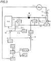
- the invention according to the second embodiment is configured to detect a smoothed value of the welding voltage and subject the cycle of the feeding rate to a feedback control so that the smoothed value of welding voltage becomes equal to the voltage setting value.
- FIG. 3 is a block diagram illustrating a welding power supply for implementing an arc welding control method according to the second embodiment of the present invention.
- This figure corresponds to FIG. 1 , and blocks identical to those of FIG. 1 are referred to by the same symbols, with explanation thereof being omitted.
- a voltage detection circuit VD a voltage smoothing circuit VAV and a feeding error amplifier circuit EF are added, and the cycle setting circuit TFR of FIG. 1 is replaced by a second cycle setting circuit TFR 2 .
- the voltage detection circuit VD detects the welding voltage Vw and outputs a voltage detection signal Vd.
- the voltage smoothing circuit VAV smoothes this voltage detection signal and outputs a welding voltage smoothed signal Vav.
- This smoothing is performed using a smoothing circuit constituted of a resistor and a capacitor, a low-pass filter, and so on.
- a time constant of the smoothing is determined by setting a cut-off frequency (about 1 to 10 Hz).
- the feeding error amplifier circuit EF amplifies an error between the voltage setting signal Er (+) and the welding voltage smoothed signal Vav ( ⁇ ) and outputs a feeding error amplified signal Ef.
- the second cycle setting circuit TFR 2 integrates the feeding error amplified signal Ef during the welding and outputs a cycle setting signal Tfr.
- the integration can be represented as Tfr32 Tf0+ ⁇ Ef ⁇ dt.
- Tf0 is a predetermined initial value.
- a value of the cycle setting signal Tfr is subjected to the feedback control and changes every moment during the welding so that a value of the welding voltage smoothed signal Vav becomes equal to a value of the voltage setting signal Er.
- a timing chart of individual signals in the welding power supply of FIG. 3 illustrating the arc welding control method according to the second embodiment of the present invention is same as that of FIG. 2 , and hence the explanation thereof is omitted.
- this embodiment differs in a point that the cycle Tf shown in FIG. 2 is subjected to the feedback control by the feeding error amplifier circuit EF and the second cycle setting circuit TFR 2 of FIG. 3 so that a value of the welding voltage smoothed signal Vav becomes equal to a value of the voltage setting signal Er.
- a smoothed value of the welding voltage is detected and the cycle of the feeding rate is subjected to the feedback control so that the welding voltage smoothed value becomes equal to the voltage setting value. Consequently the cycle of the feeding rate is subjected to the feedback control so that the welding voltage smoothed value becomes equal to the voltage setting value in correspondence to the change of the droplet transfer state according to the change of the voltage setting value.
- the state where the welding voltage smoothed value becomes equal to the voltage setting value is a state that a cycle of the forward feeding and the reverse feeding as to the feeding rate is not asynchronous with a cycle of the short-circuiting period and the arc period and so the welding state is stable.
- the invention according to a third embodiment relates to a case where a waveform of the feeding rate is trapezoidal, and is configured to change the cycle of the feeding rate by changing a waveform parameter of the feeding rate based on the voltage setting value.
- FIG. 4 is a block diagram illustrating a welding power supply for implementing an arc welding control method according to the third embodiment of the present invention.
- This figure corresponds to FIG. 1 , and blocks identical to those of FIG. 1 are referred to by the same symbols, with explanation thereof being omitted.
- the cycle setting circuit TFR, the amplitude setting circuit WFR and the forward-feeding side shift-amount setting circuit SFR of FIG. 1 are omitted.
- a forward-feeding acceleration-period setting circuit TSUR a forward-feeding deceleration-period setting circuit TSDR, a reverse-feeding acceleration-period setting circuit TRUR, a reverse-feeding deceleration-period setting circuit TRDR, a forward-feeding amplitude setting circuit WSR, a reverse-feeding amplitude setting circuit WRR, a voltage detection circuit VD and a short-circuit discrimination circuit SD are added.
- the feeding-rate setting circuit FR of FIG. 1 is replaced by a second feeding-rate setting circuit FR 2 .
- the forward-feeding acceleration-period setting circuit TSUR uses the voltage setting signal Er as input, calculates a forward-feeding acceleration period according to a predetermined forward-feeding acceleration-period setting function and outputs the calculated period as a forward-feeding acceleration-period setting signal Tsur.
- the forward-feeding acceleration-period setting function is a function that the larger the voltage setting signal Er is, the larger a value of the forward-feeding acceleration-period setting signal Tsur becomes. This function is set in advance by an experiment.
- the forward-feeding deceleration-period setting circuit TSDR outputs a predetermined forward-feeding deceleration-period setting signal Tsdr.
- the reverse-feeding acceleration-period setting circuit TRUR outputs a predetermined reverse-feeding acceleration-period setting signal Trur.
- the reverse-feeding deceleration-period setting circuit TRDR uses the voltage setting signal Er as input, calculates a reverse-feeding deceleration period according to a predetermined reverse-feeding deceleration-period setting function and outputs the calculated period as a reverse-feeding deceleration-period setting signal Trdr.
- the reverse-feeding deceleration-period setting function is a function that the larger the voltage setting signal Er is, the larger a value of the reverse-feeding deceleration-period setting signal Trdr becomes. This function is set in advance by an experiment.
- the forward-feeding amplitude setting circuit WSR outputs a predetermined forward-feeding amplitude setting signal Wsr.
- the reverse-feeding amplitude setting circuit WRR outputs a predetermined reverse-feeding amplitude setting signal Wrr.
- the voltage detection circuit VD detects the welding voltage Vw and outputs a voltage detection signal Vd. Using the voltage detection signal Vd as input, the short-circuit discrimination circuit SD outputs a short-circuit discrimination signal Sd. In a case where e voltage detection signal Vd is less than a short-circuit discrimination value (about 10V), the discrimination circuit determines to be a short-circuiting period and outputs the discrimination signal of a high level. In a case where the voltage detection signal is the short-circuit discrimination value or more, the discrimination circuit determines to be an arc period and outputs the discrimination signal of a low level.
- a short-circuit discrimination value about 10V
- the second feeding-rate setting circuit FR 2 uses the forward-feeding acceleration-period setting signal Tsur, the forward-feeding deceleration-period setting signal Tsdr, the reverse-feeding acceleration-period setting signal Trur, the reverse-feeding deceleration-period setting signal Trdr, the forward-feeding amplitude setting signal Wsr, the reverse-feeding amplitude setting signal Wrr and the short-circuit discrimination signal Sd as input, the second feeding-rate setting circuit FR 2 generates a feeding rate pattern according to the following processing and outputs as a feeding-rate setting signal Fr. A period where the feeding-rate setting signal Fr is 0 or more is the forward feeding period, whilst a period where this signal is smaller than 0 is the reverse feeding period.
- FIG. 5 is a timing chart illustrating individual signals in a welding power supply of FIG. 4 , showing the arc welding control method according to the third embodiment of the present invention.
- A of this figure shows temporal change of the feeding rate Fw
- B of this figure shows temporal change of the welding current Iw
- C of this figure shows temporal change of the welding voltage Vw
- D of this figure shows temporal change of the short-circuit discrimination signal Sd.
- the feeding rate Fw shown in (A) of this figure is controlled to a value of the feeding-rate setting signal Fr outputted from the second feeding-rate setting circuit FR 2 of FIG. 4 .
- the feeding-rate setting signal Fr is formed by the forward-feeding acceleration period Tsu determined by the forward-feeding acceleration-period setting signal Tsur of FIG. 4 , the forward-feeding peak period Tsp continuing until the generation of short circuit, the forward-feeding deceleration period Tsd determined by the forward-feeding deceleration-period setting signal Tsdr of FIG. 4 , the reverse-feeding acceleration period Tru determined by the reverse-feeding acceleration-period setting signal Trur of FIG.
- the feeding-rate setting signal Fr has the feeding pattern changing in the form of the positive and negative trapezoidal waves.
- the feeding rate Fw enters into the predetermined reverse-feeding acceleration period Tru from a time t 1 to a time t 2 and accelerates from 0 to the reverse-feeding peak value Wrp.
- the short-circuiting period continues during this period.
- the short-circuit discrimination signal Sd changes to the low level (arc period).
- the feeding-rate setting signal shifts to the predetermined reverse-feeding deceleration period Trd of the time t 3 to a time t 4 .
- the feeding rate Fw decelerates from the reverse-feeding peak value Wrp to 0.
- the welding voltage Vw rapidly increases to the arc voltage value of several tens of volts as shown in (C) of this figure, whilst the welding current Iw gradually reduces during the arc period as shown in (B) of this figure.
- the feeding-rate setting signal shifts to the predetermined forward-feeding acceleration period Tsu of the time t 4 to a time t 5 .
- the feeding rate Fw accelerates from 0 to the forward-feeding peak value Wsp as shown in (A) of this figure.
- the arc period continues during this period.
- the short-circuit discrimination signal Sd changes to the high level (short-circuiting period).
- the feeding-rate setting signal shifts to the predetermined forward-feeding deceleration period Tsd of the time t 6 to a time t 7 .
- the feeding rate Fw decelerates from the forward-feeding peak value Wsp to 0.
- the welding voltage Vw rapidly reduces to the short-circuit voltage value of a few volts as shown in (C) of this figure, whilst the welding current Iw increases gradually during the short-circuiting period as shown in (B) of this figure.
- the welding state becomes unstable.
- the forward-feeding peak period Tsp and the reverse-feeding peak period Tip terminate in synchronous with the occurrence of short circuit and the generation of arc, respectively, these peak periods are not constant. Thus the cycle of the feeding rate Fw cannot be directly set to a predetermined value.
- an average value of the forward-feeding peak period Tsp and an average value of the reverse-feeding peak period Trp at every unit time become almost respective constant values.
- an average value of the cycle of the feeding rate Fw at every unit time can be set to a desired value by adjusting at least one of the forward-feeding acceleration period Tsu, the forward-feeding deceleration period Tsd, the reverse-feeding acceleration period Tru or the reverse-feeding deceleration period Trd each of which is the individual waveform parameter of the feeding rate Fw and can be set to an individual desired value.
- an average value of the cycle of the feeding rate Fw at every unit time can be optimized by changing at least one of the forward-feeding acceleration period Tsu, the forward-feeding deceleration period Tsd, the reverse-feeding acceleration period Tru or the reverse-feeding deceleration period Trd in linkage with the voltage setting signal Er. Consequently the welding state can be maintained stably even if the voltage setting signal Er changes.
- FIG. 4 shows an example where the forward-feeding acceleration period Tsu and the reverse-feeding deceleration period Trd as the waveform parameters of the feeding rate Fw are automatically changed according to predetermined respective functions in linkage with the voltage setting signal Er,
- a forward-feeding acceleration-period setting function and a reverse-feeding deceleration-period setting function are defined in the following manner in advance.
- An average value of the cycle of the feeding rate Fw stabilizing the welding state is obtained by an experiment at every value of the voltage setting signal Er.
- Both values of the forward-feeding acceleration period Tsu and the reverse-feeding deceleration period Trd are determined so as to attain the obtained average value of the cycle.
- the individual functions are defined from these determined values. Also in a case where the waveform parameters of the feeding rate Fw are a combination of other periods, functions can be defined in the similar manner.
- the forward-feeding deceleration period Tsd and the reverse-feeding acceleration period Tru during the short-circuiting period are set to predetermined values, and if at least one of the forward-feeding acceleration period Tsu or the reverse-feeding deceleration period Trd during the arc period is optimized in linkage with the voltage setting signal Er, the welding state can be more stabilized.
- the invention according to a fourth embodiment is configured to, in the third embodiment, change a setting value of the cycle of the feeding rate based on the voltage setting value, detect an average value of the cycle of the feeding rate, and subject the waveform parameters of the feeding rate to feedback control so that this average value of the cycle becomes equal to the setting value of the cycle.
- FIG. 6 is a block diagram illustrating a welding power supply for implementing an arc welding control method according to the fourth embodiment of the present invention.
- This figure corresponds to FIG. 4 , and blocks identical to those of FIG. 4 are referred to by the same symbols, with explanation thereof being omitted.
- a cycle setting circuit TFR same as that of FIG. 1 is added, and further a cycle average value detection circuit TFD, a cycle error amplifier circuit ET, a second forward-feeding acceleration-period setting circuit TSUR 2 and a second reverse-feeding deceleration-period setting circuit TRDR 2 are added.
- TFD cycle average value detection circuit
- ET cycle error amplifier circuit
- TSUR 2 second forward-feeding acceleration-period setting circuit
- TRDR 2 reverse-feeding deceleration-period setting circuit
- the cycle setting circuit TFR calculates a cycle according to a predetermined cycle setting function and outputs the calculated cycle as a cycle setting signal Tfr. This circuit is the same as that of FIG. 1 .
- the cycle average value detection circuit TFD detects an average value of a cycle of the feeding-rate setting signal Fr per unit time and outputs a cycle average value detection signal Tfd.
- the cycle error amplifier circuit ET amplifiers an error between the cycle setting signal Tfr ( ⁇ ) and the cycle average value detection signal Tfd (+) and outputs a cycle error amplified signal Et.
- the second forward-feeding acceleration-period setting circuit TSUR 2 integrates the cycle error amplified signal Et during the welding and outputs a forward-feeding acceleration-period setting signal Tsur.
- Tsu0 is a predetermined initial value.
- a value of the forward-feeding acceleration-period setting signal Tsur is subjected to the feedback control and changes every moment during the welding so that an average value of the cycle of the feeding rate Fw becomes equal to a value of the cycle setting signal Tfr.
- the second reverse-feeding deceleration-period setting circuit TRDR 2 integrates the cycle error amplified signal Et during the welding and outputs a reverse-feeding deceleration-period setting signal Trdr.
- Trd0 is a predetermined initial value.
- a value of the reverse-feeding deceleration-period setting signal Trdr is subjected to the feedback control and changes every moment during the welding so that an average value of the cycle of the feeding rate Fw becomes equal to a value of the cycle setting signal Tfr.
- a timing chart of individual signals in a welding power supply of FIG. 6 illustrating the arc welding control method according to the fourth embodiment of the present invention is same as that of FIG. 5 , and hence the explanation thereof is omitted.
- this embodiment differs in a point that the forward-feeding acceleration period Tsu and the reverse-feeding deceleration period Trd shown in FIG. 5 are subjected to the feedback control by the second forward-feeding acceleration-period setting circuit TSUR 2 and the second reverse-feeding deceleration-period setting circuit TRDR 2 respectively so that an average value of the cycle of the feeding rate Fw becomes equal to a value of the cycle setting signal Tfr.
- the fourth embodiment is explained as to the case where the waveform parameters of the feeding rate Fw are the forward-feeding acceleration period Tsu and the reverse-feeding deceleration period Trd.
- the waveform parameter of the feeding rate Fw may be at least one of the forward-feeding acceleration period Tsu, the forward-feeding deceleration period Tsd, the reverse-feeding acceleration period Tru or the reverse-feeding deceleration period Trd.
- the waveform parameters of the feeding rate are subjected to the feedback control so that an average value of the cycle of the feeding rate becomes equal to the cycle setting value.
- an average value of the cycle of the feeding rate becomes strictly equal to the cycle setting value, stability of the welding state at the time of change of the voltage setting value can be improved.
- the present invention can provide the arc welding control method which, in the welding of alternating the feeding rate between the forward feeding period and the reverse feeding period, can maintain the welding state stably even if the voltage setting value changes.
Landscapes
- Engineering & Computer Science (AREA)
- Physics & Mathematics (AREA)
- Plasma & Fusion (AREA)
- Mechanical Engineering (AREA)
- Theoretical Computer Science (AREA)
- Arc Welding Control (AREA)
Abstract
Description
Claims (10)
Applications Claiming Priority (3)
| Application Number | Priority Date | Filing Date | Title |
|---|---|---|---|
| JP2014165785 | 2014-08-18 | ||
| JP2014-165785 | 2014-08-18 | ||
| PCT/JP2015/071673 WO2016027638A1 (en) | 2014-08-18 | 2015-07-30 | Arc welding control method |
Publications (2)
| Publication Number | Publication Date |
|---|---|
| US20170216952A1 US20170216952A1 (en) | 2017-08-03 |
| US10695855B2 true US10695855B2 (en) | 2020-06-30 |
Family
ID=55350584
Family Applications (1)
| Application Number | Title | Priority Date | Filing Date |
|---|---|---|---|
| US15/500,649 Active 2037-01-19 US10695855B2 (en) | 2014-08-18 | 2015-07-30 | Arc welding control method |
Country Status (6)
| Country | Link |
|---|---|
| US (1) | US10695855B2 (en) |
| EP (1) | EP3184227B1 (en) |
| JP (1) | JP6532137B2 (en) |
| KR (1) | KR102306504B1 (en) |
| CN (1) | CN106457445B (en) |
| WO (1) | WO2016027638A1 (en) |
Families Citing this family (5)
| Publication number | Priority date | Publication date | Assignee | Title |
|---|---|---|---|---|
| EP3782756B1 (en) | 2018-04-18 | 2022-05-04 | Panasonic Intellectual Property Management Co., Ltd. | Arc welding control method |
| JP7017979B2 (en) * | 2018-04-26 | 2022-02-09 | 株式会社神戸製鋼所 | Welding power supply and welding power supply control method |
| CN108890084B (en) * | 2018-07-18 | 2020-07-14 | 唐山松下产业机器有限公司 | Welding equipment, welding control device and welding control method |
| JP7039413B2 (en) * | 2018-07-26 | 2022-03-22 | 株式会社ダイヘン | Arc welding control method |
| JP7158327B2 (en) * | 2018-12-21 | 2022-10-21 | 株式会社ダイヘン | Arc welding control method |
Citations (9)
| Publication number | Priority date | Publication date | Assignee | Title |
|---|---|---|---|---|
| US3205396A (en) | 1962-12-26 | 1965-09-07 | Automatic Welding Company | Arc welding apparatus |
| JPS521266B1 (en) | 1967-07-18 | 1977-01-13 | ||
| JPH09277044A (en) | 1996-04-10 | 1997-10-28 | Daihen Corp | Arc length recovery control method of pulse arc welding and welding equipment |
| CN1712169A (en) | 2004-06-23 | 2005-12-28 | 株式会社大亨 | AC pulse arc welding method |
| CN101274385A (en) | 2007-03-29 | 2008-10-01 | 株式会社大亨 | Feed control method for consumable electrode AC arc welding |
| WO2011013305A1 (en) | 2009-07-29 | 2011-02-03 | パナソニック株式会社 | Arc welding method and arc welding device |
| EP2292364A1 (en) | 2009-06-19 | 2011-03-09 | Panasonic Corporation | Consumable electrode arc welding method and consumable electrode arc welding device |
| EP2402104A1 (en) | 2009-07-29 | 2012-01-04 | Panasonic Corporation | Arc welding method and arc welding device |
| US10376981B2 (en) * | 2013-07-17 | 2019-08-13 | Daihen Corporation | Arc welding power supply and methods for controlling arc welding power supply |
Family Cites Families (2)
| Publication number | Priority date | Publication date | Assignee | Title |
|---|---|---|---|---|
| JP6145698B2 (en) * | 2013-03-08 | 2017-06-14 | パナソニックIpマネジメント株式会社 | Arc welding control method and arc welding apparatus |
| JP6125932B2 (en) * | 2013-07-10 | 2017-05-10 | 株式会社ダイヘン | Power supply apparatus for arc welding and control method for power supply apparatus for arc welding |
-
2015
- 2015-07-30 CN CN201580032002.1A patent/CN106457445B/en not_active Expired - Fee Related
- 2015-07-30 EP EP15834443.2A patent/EP3184227B1/en active Active
- 2015-07-30 WO PCT/JP2015/071673 patent/WO2016027638A1/en not_active Ceased
- 2015-07-30 US US15/500,649 patent/US10695855B2/en active Active
- 2015-07-30 KR KR1020177000493A patent/KR102306504B1/en not_active Expired - Fee Related
- 2015-07-30 JP JP2016543887A patent/JP6532137B2/en active Active
Patent Citations (20)
| Publication number | Priority date | Publication date | Assignee | Title |
|---|---|---|---|---|
| US3205396A (en) | 1962-12-26 | 1965-09-07 | Automatic Welding Company | Arc welding apparatus |
| JPS521266B1 (en) | 1967-07-18 | 1977-01-13 | ||
| JPH09277044A (en) | 1996-04-10 | 1997-10-28 | Daihen Corp | Arc length recovery control method of pulse arc welding and welding equipment |
| CN1712169A (en) | 2004-06-23 | 2005-12-28 | 株式会社大亨 | AC pulse arc welding method |
| US20050284854A1 (en) | 2004-06-23 | 2005-12-29 | Daihen Corporation | AC pulse arc welding method |
| CN101274385A (en) | 2007-03-29 | 2008-10-01 | 株式会社大亨 | Feed control method for consumable electrode AC arc welding |
| US20080237208A1 (en) | 2007-03-29 | 2008-10-02 | Daihen Corporation | Feed control method for consumable electrode AC arc welding |
| US20130082041A1 (en) | 2009-06-19 | 2013-04-04 | Panasonic Corporation | Consumable electrode arc welding method and consumable electrode arc welding device |
| EP2292364A1 (en) | 2009-06-19 | 2011-03-09 | Panasonic Corporation | Consumable electrode arc welding method and consumable electrode arc welding device |
| CN102149501A (en) | 2009-06-19 | 2011-08-10 | 松下电器产业株式会社 | Consumable electrode arc welding method and consumable electrode arc welding device |
| US20120074114A1 (en) * | 2009-06-19 | 2012-03-29 | Panasonic Corporation | Consumable electrode arc welding method and consumable electrode arc welding device |
| US20130082040A1 (en) | 2009-06-19 | 2013-04-04 | Panasonic Corporation | Consumable electrode arc welding method and consumable electrode arc welding device |
| EP2402104A1 (en) | 2009-07-29 | 2012-01-04 | Panasonic Corporation | Arc welding method and arc welding device |
| CN102361722A (en) | 2009-07-29 | 2012-02-22 | 松下电器产业株式会社 | Arc welding method and arc welding device |
| US20120111842A1 (en) | 2009-07-29 | 2012-05-10 | Panasonic Corporation | Arc welding method and arc welding apparatus |
| US20120145691A1 (en) | 2009-07-29 | 2012-06-14 | Panasonic Corporation | Arc welding method and arc welding apparatus |
| WO2011013305A1 (en) | 2009-07-29 | 2011-02-03 | パナソニック株式会社 | Arc welding method and arc welding device |
| JP5201266B2 (en) | 2009-07-29 | 2013-06-05 | パナソニック株式会社 | Arc welding method and arc welding apparatus |
| US8993925B2 (en) | 2009-07-29 | 2015-03-31 | Panasonic Intellectual Property Management Co., Ltd. | Arc welding method and arc welding apparatus |
| US10376981B2 (en) * | 2013-07-17 | 2019-08-13 | Daihen Corporation | Arc welding power supply and methods for controlling arc welding power supply |
Non-Patent Citations (3)
| Title |
|---|
| Chinese Office Action issued for Chinese Patent Application No. 201580032002.1 dated Aug. 1, 2018 along with the English translation. |
| Extended European Search Report issued for the European Patent Application No. 15834443.2 dated May 4, 2018. |
| International Search Report (ISR) issued in International Patent Application No. PCT/JP2015/071673, dated Oct. 20, 2015; and written opinion with a corresponding English translation. |
Also Published As
| Publication number | Publication date |
|---|---|
| US20170216952A1 (en) | 2017-08-03 |
| JPWO2016027638A1 (en) | 2017-06-01 |
| KR102306504B1 (en) | 2021-09-28 |
| JP6532137B2 (en) | 2019-06-19 |
| EP3184227A1 (en) | 2017-06-28 |
| EP3184227B1 (en) | 2023-11-01 |
| WO2016027638A1 (en) | 2016-02-25 |
| CN106457445B (en) | 2019-09-24 |
| CN106457445A (en) | 2017-02-22 |
| KR20170034882A (en) | 2017-03-29 |
| EP3184227A4 (en) | 2018-05-30 |
Similar Documents
| Publication | Publication Date | Title |
|---|---|---|
| JP6472436B2 (en) | Arc welding control method | |
| US10456853B2 (en) | Arc welding control method | |
| US11033979B2 (en) | Arc welding control method | |
| US10695855B2 (en) | Arc welding control method | |
| US10413988B2 (en) | Arc welding control method | |
| US10493553B2 (en) | Arc welding control method | |
| JP6537137B2 (en) | Reverse feed arc welding method | |
| US10391578B2 (en) | Arc welding control method | |
| US10456852B2 (en) | Arc welding control method | |
| US10220464B2 (en) | Arc welding control method | |
| JP6347721B2 (en) | Arc welding control method | |
| JP2015231632A (en) | Arc-welding control method | |
| WO2015166793A1 (en) | Arc welding control method | |
| KR102233253B1 (en) | Arc welding control method | |
| JP6261614B2 (en) | Arc welding control method |
Legal Events
| Date | Code | Title | Description |
|---|---|---|---|
| AS | Assignment |
Owner name: DAIHEN CORPORATION, JAPAN Free format text: ASSIGNMENT OF ASSIGNORS INTEREST;ASSIGNOR:IDE, AKIHIRO;REEL/FRAME:041133/0703 Effective date: 20170119 |
|
| STPP | Information on status: patent application and granting procedure in general |
Free format text: DOCKETED NEW CASE - READY FOR EXAMINATION |
|
| STPP | Information on status: patent application and granting procedure in general |
Free format text: NON FINAL ACTION MAILED |
|
| STPP | Information on status: patent application and granting procedure in general |
Free format text: RESPONSE TO NON-FINAL OFFICE ACTION ENTERED AND FORWARDED TO EXAMINER |
|
| STPP | Information on status: patent application and granting procedure in general |
Free format text: NOTICE OF ALLOWANCE MAILED -- APPLICATION RECEIVED IN OFFICE OF PUBLICATIONS |
|
| STCF | Information on status: patent grant |
Free format text: PATENTED CASE |
|
| MAFP | Maintenance fee payment |
Free format text: PAYMENT OF MAINTENANCE FEE, 4TH YEAR, LARGE ENTITY (ORIGINAL EVENT CODE: M1551); ENTITY STATUS OF PATENT OWNER: LARGE ENTITY Year of fee payment: 4 |