US10695847B2 - Saw height adjustment mechanism having a flexible shaft - Google Patents
Saw height adjustment mechanism having a flexible shaft Download PDFInfo
- Publication number
- US10695847B2 US10695847B2 US15/948,725 US201815948725A US10695847B2 US 10695847 B2 US10695847 B2 US 10695847B2 US 201815948725 A US201815948725 A US 201815948725A US 10695847 B2 US10695847 B2 US 10695847B2
- Authority
- US
- United States
- Prior art keywords
- flexible shaft
- rotation
- coils
- assembly
- height adjustment
- Prior art date
- Legal status (The legal status is an assumption and is not a legal conclusion. Google has not performed a legal analysis and makes no representation as to the accuracy of the status listed.)
- Expired - Fee Related
Links
- 230000007246 mechanism Effects 0.000 title description 23
- 238000005520 cutting process Methods 0.000 claims abstract description 54
- 238000004804 winding Methods 0.000 claims description 22
- 238000000034 method Methods 0.000 claims description 8
- 238000013519 translation Methods 0.000 claims description 4
- 239000000428 dust Substances 0.000 description 14
- 238000005452 bending Methods 0.000 description 7
- 238000003754 machining Methods 0.000 description 6
- 239000002023 wood Substances 0.000 description 4
- 238000012546 transfer Methods 0.000 description 3
- 238000010276 construction Methods 0.000 description 2
- 230000008602 contraction Effects 0.000 description 2
- 238000012986 modification Methods 0.000 description 2
- 230000004048 modification Effects 0.000 description 2
- 230000000007 visual effect Effects 0.000 description 2
- 229910000760 Hardened steel Inorganic materials 0.000 description 1
- 239000004743 Polypropylene Substances 0.000 description 1
- 238000009825 accumulation Methods 0.000 description 1
- 230000004075 alteration Effects 0.000 description 1
- 229910052782 aluminium Inorganic materials 0.000 description 1
- XAGFODPZIPBFFR-UHFFFAOYSA-N aluminium Chemical compound [Al] XAGFODPZIPBFFR-UHFFFAOYSA-N 0.000 description 1
- 230000000712 assembly Effects 0.000 description 1
- 238000000429 assembly Methods 0.000 description 1
- 230000009286 beneficial effect Effects 0.000 description 1
- 238000009954 braiding Methods 0.000 description 1
- 239000006227 byproduct Substances 0.000 description 1
- 238000004140 cleaning Methods 0.000 description 1
- 230000001010 compromised effect Effects 0.000 description 1
- 238000011109 contamination Methods 0.000 description 1
- 238000013461 design Methods 0.000 description 1
- 230000000916 dilatatory effect Effects 0.000 description 1
- 230000010339 dilation Effects 0.000 description 1
- 229920002457 flexible plastic Polymers 0.000 description 1
- 230000003993 interaction Effects 0.000 description 1
- 229920001684 low density polyethylene Polymers 0.000 description 1
- 239000004702 low-density polyethylene Substances 0.000 description 1
- 238000012423 maintenance Methods 0.000 description 1
- 230000007257 malfunction Effects 0.000 description 1
- 238000004519 manufacturing process Methods 0.000 description 1
- 239000000463 material Substances 0.000 description 1
- 229910052751 metal Inorganic materials 0.000 description 1
- 239000002184 metal Substances 0.000 description 1
- 229910001092 metal group alloy Inorganic materials 0.000 description 1
- 239000002245 particle Substances 0.000 description 1
- -1 polypropylene Polymers 0.000 description 1
- 229920001155 polypropylene Polymers 0.000 description 1
- 230000008569 process Effects 0.000 description 1
- 239000000047 product Substances 0.000 description 1
- 230000001737 promoting effect Effects 0.000 description 1
- 230000004044 response Effects 0.000 description 1
- 238000003466 welding Methods 0.000 description 1
Images


Classifications
-
- B—PERFORMING OPERATIONS; TRANSPORTING
- B23—MACHINE TOOLS; METAL-WORKING NOT OTHERWISE PROVIDED FOR
- B23D—PLANING; SLOTTING; SHEARING; BROACHING; SAWING; FILING; SCRAPING; LIKE OPERATIONS FOR WORKING METAL BY REMOVING MATERIAL, NOT OTHERWISE PROVIDED FOR
- B23D45/00—Sawing machines or sawing devices with circular saw blades or with friction saw discs
- B23D45/06—Sawing machines or sawing devices with circular saw blades or with friction saw discs with a circular saw blade arranged underneath a stationary work-table
- B23D45/068—Sawing machines or sawing devices with circular saw blades or with friction saw discs with a circular saw blade arranged underneath a stationary work-table the saw blade being adjustable according to depth or angle of cut
-
- B—PERFORMING OPERATIONS; TRANSPORTING
- B27—WORKING OR PRESERVING WOOD OR SIMILAR MATERIAL; NAILING OR STAPLING MACHINES IN GENERAL
- B27B—SAWS FOR WOOD OR SIMILAR MATERIAL; COMPONENTS OR ACCESSORIES THEREFOR
- B27B5/00—Sawing machines working with circular or cylindrical saw blades; Components or equipment therefor
- B27B5/02—Sawing machines working with circular or cylindrical saw blades; Components or equipment therefor characterised by a special purpose only
-
- B—PERFORMING OPERATIONS; TRANSPORTING
- B27—WORKING OR PRESERVING WOOD OR SIMILAR MATERIAL; NAILING OR STAPLING MACHINES IN GENERAL
- B27B—SAWS FOR WOOD OR SIMILAR MATERIAL; COMPONENTS OR ACCESSORIES THEREFOR
- B27B5/00—Sawing machines working with circular or cylindrical saw blades; Components or equipment therefor
- B27B5/16—Saw benches
- B27B5/22—Saw benches with non-feedable circular saw blade
- B27B5/24—Saw benches with non-feedable circular saw blade the saw blade being adjustable according to depth or angle of cut
- B27B5/243—Saw benches with non-feedable circular saw blade the saw blade being adjustable according to depth or angle of cut the saw blade being arranged underneath the work-table
-
- B—PERFORMING OPERATIONS; TRANSPORTING
- B27—WORKING OR PRESERVING WOOD OR SIMILAR MATERIAL; NAILING OR STAPLING MACHINES IN GENERAL
- B27B—SAWS FOR WOOD OR SIMILAR MATERIAL; COMPONENTS OR ACCESSORIES THEREFOR
- B27B5/00—Sawing machines working with circular or cylindrical saw blades; Components or equipment therefor
- B27B5/29—Details; Component parts; Accessories
-
- F—MECHANICAL ENGINEERING; LIGHTING; HEATING; WEAPONS; BLASTING
- F16—ENGINEERING ELEMENTS AND UNITS; GENERAL MEASURES FOR PRODUCING AND MAINTAINING EFFECTIVE FUNCTIONING OF MACHINES OR INSTALLATIONS; THERMAL INSULATION IN GENERAL
- F16C—SHAFTS; FLEXIBLE SHAFTS; ELEMENTS OR CRANKSHAFT MECHANISMS; ROTARY BODIES OTHER THAN GEARING ELEMENTS; BEARINGS
- F16C1/00—Flexible shafts; Mechanical means for transmitting movement in a flexible sheathing
- F16C1/02—Flexible shafts; Mechanical means for transmitting movement in a flexible sheathing for conveying rotary movements
- F16C1/06—Flexible shafts; Mechanical means for transmitting movement in a flexible sheathing for conveying rotary movements with guiding sheathing, tube or box
-
- F—MECHANICAL ENGINEERING; LIGHTING; HEATING; WEAPONS; BLASTING
- F16—ENGINEERING ELEMENTS AND UNITS; GENERAL MEASURES FOR PRODUCING AND MAINTAINING EFFECTIVE FUNCTIONING OF MACHINES OR INSTALLATIONS; THERMAL INSULATION IN GENERAL
- F16C—SHAFTS; FLEXIBLE SHAFTS; ELEMENTS OR CRANKSHAFT MECHANISMS; ROTARY BODIES OTHER THAN GEARING ELEMENTS; BEARINGS
- F16C2322/00—Apparatus used in shaping articles
- F16C2322/34—Sawing machines
Definitions
- This invention relates to power equipment, and in particular to a table saw.
- Table saws are used in a variety of diverse applications for cutting wood products, often in the construction industry. In particular, in settings such as construction jobsites and machine shops, table saws are used to cut and shape a wide range of wood types and piece shapes. For example, framers use table saws for rough-cutting lumber, while finishing carpenters use such saws for making precise rip and miter cuts.
- Such table saws are often required to suit a range of cutting and machining requirements, as they are capable of cutting workpieces at varying angles and also adjusting in height.
- Height adjustable table saws are particularly beneficial in that the height of the cutting blade can be raised and lowered in order to accommodate a wide variety of machining requirements.
- Height adjustable table saws typically include height adjustment mechanisms configured to raise and lower the cutting blade of the table saw.
- one such arrangement includes a pair of bevel gears having involute teeth.
- one of the bevel gears is connected to a horizontally oriented handle wheel while a second bevel gear is connected to a vertical shaft that is connected via a cam mechanism to the cutting blade.
- the gear teeth of the two bevel gears mesh with one another in order to transfer rotation of the handle wheel into a vertical movement of the cutting blade.
- One current solution for reducing dust and debris contamination issues in the bevel gears is to cease operation of the table saw and clean the gear assembly to remove dust, wood chips, and other debris from the bevel gears.
- this process can be time consuming and reduces the efficiency of the table saw.
- Another possible solution includes mounting the gear of the vertical shaft above the gear of the horizontal shaft such that the top gear creates a “canopy” over the lower gear, thus reducing dust and debris build-up on the gears.
- the canopy only slows the build-up of dust and debris. Eventually, the dust and debris will accumulate and compromise the rotation of the gears and thus the efficiency of the device.
- a table saw in one embodiment, includes a table assembly, a cutting assembly, and a height adjustment assembly.
- the table assembly includes a table top surface that defines a blade opening.
- the cutting assembly is arranged below the table assembly and is configured to be movable relative to the table top surface.
- the height adjustment assembly is operably connected to the cutting assembly and includes an input member, an output member, and a flexible shaft.
- the output member is operably connected to the cutting assembly and is configured such that rotation of the output member causes the cutting assembly to move relative to the table top surface.
- the flexible shaft has a nonlinear central axis, a first end operably connected to the input member, and a second end operably connected to the output member. The flexible shaft is configured such that rotation of the input member causes rotation of the first end and the second end of the flexible shaft, and rotation of the second end of the flexible shaft causes rotation of the output member.
- the first rotational axis is oblique to the second rotational axis.
- the first rotational axis and the second rotational axis do not intersect.
- the table saw further includes a bevel adjustment member configured to adjust a bevel angle of the cutting assembly.
- the first rotational axis is spaced apart from the bevel adjustment member.
- the first end of the flexible shaft is fixedly attached to the input member and the second end is fixedly attached to the output member.
- the cutting assembly includes a translation member operably connected to the output member.
- the translation member is configured to convert the rotation of the output member into translational movement of the cutting assembly.
- the flexible shaft includes a primary central wire, at least one first plurality of coils, and at least one second plurality of coils.
- the central wire extends from the first end to the second end of the flexible shaft.
- the at least one first plurality of coils is wound around the central wire in a first winding direction
- the at least one second plurality of coils is wound around the at least one first plurality of coils in a second winding direction.
- the at least one first plurality of coils is right-hand wound, and the at least one second plurality of coils is left-hand wound.
- rotation of the flexible shaft causes the at least one first plurality of coils to generate a clamping force on the primary central wire
- rotation of the flexible shaft causes the at least one second plurality of coils to generate a clamping force on the at least one first plurality of coils.
- the flexible shaft includes a first plurality of coils.
- the first plurality of coils includes a first plurality of clamping coils, a second plurality of clamping coils, and a plurality of elongated coils.
- the first plurality of clamping coils is wound at a first end region of the flexible shaft and has a first inner coil diameter.
- the second plurality of clamping coils is wound at a second end region of the flexible shaft and has a second inner coil diameter.
- the plurality of elongated coils is wound between the first plurality of clamping coils and the second plurality of clamping coils and has a third inner coil diameter that is greater than the first and second inner coil diameters.
- a height adjustment assembly for a table saw in another embodiment, includes an input member, an output member, and a flexible shaft.
- the output member is operably connected to a cutting assembly of the table saw and is configured such that rotation of the output member causes the cutting assembly to move relative to a table top surface of the table saw.
- the flexible shaft has a nonlinear central axis, a first end operably connected to the input member, and a second end operably connected to the output member.
- the flexible shaft is configured such that rotation of the input member causes rotation of the first end and the second end of the flexible shaft, and rotation of the second end of the flexible shaft causes rotation of the output member.
- rotation of the input member causes rotation of the first end of the flexible shaft about a first rotational axis
- rotation of flexible shaft causes rotation of the second end of the flexible shaft about a second rotational axis that is not parallel to the first rotational axis
- the first rotational axis is oblique to the second rotational axis.
- the first rotational axis and the second rotational axis do not intersect.
- the height adjustment assembly further includes a bevel adjustment member configured to adjust a bevel angle of the cutting assembly.
- the first rotational axis is spaced apart from the bevel adjustment member.
- the flexible shaft includes a primary central wire, at least one first plurality of coils, and at least one second plurality of coils.
- the central wire extends from the first end to the second end of the flexible shaft.
- the at least one first plurality of coils is wound around the central wire in a first winding direction
- the at least one second plurality of coils is wound around the at least one first plurality of coils in a second winding direction.
- rotation of the flexible shaft causes the at least one first plurality of coils to generate a clamping force on the primary central wire, and rotation of the flexible shaft causes the at least one second plurality of coils to generate a clamping force on the at least one first plurality of coils.
- a method for adjusting a height of a cutting assembly of a table saw includes rotating an input member of a height adjustment assembly, rotating an output member of the height adjustment assembly, and moving the cutting assembly relative to a table top surface of the table saw.
- Rotating the input member causes rotation of a first end and second end of a flexible shaft of the height adjustment assembly, the flexible shaft having a nonlinear central axis.
- the first end of the flexible shaft is operably connected to the input member and the second end of the flexible shaft is operably connected to the output member.
- the output member is operably connected to the cutting assembly. Rotating the output member is carried out via the rotation of the second end of the flexible shaft. Moving the cutting assembly relative to the table top surface of the table saw is carried out via the rotation of the output member.
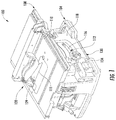
- FIG. 1 is a front perspective view of a table saw assembly having a saw blade height adjustment mechanism.
- FIG. 2 is a cut-away perspective view of the table saw assembly of FIG. 1 with a base frame of the table saw removed for clarity.
- FIG. 3 is a side elevation view of the saw blade height adjustment mechanism of the table saw assembly of FIG. 1 .
- FIG. 4 is a perspective view of the saw blade height adjustment mechanism of FIG. 3 .
- FIG. 5 is a perspective view of a flexible shaft of the saw blade height adjustment mechanism of FIG. 3 .
- FIG. 6A is a cut-away side elevation view of a flexible shaft of the saw blade height adjustment mechanism of FIG. 3 .
- FIG. 6B is a side elevation view of a flexible shaft of the saw blade height adjustment mechanism of FIG. 3 .
- FIG. 7 is a side elevation view of the saw blade height adjustment mechanism of the table saw assembly of FIG. 1 having another shaft arrangement.
- FIG. 8 is a perspective view of another flexible shaft of the saw blade height adjustment mechanism of FIG. 3 .
- FIG. 9 is a side elevation view of another flexible shaft of the saw blade height adjustment mechanism of FIG. 3 .
- FIG. 10 is a side elevation view of the saw blade height adjustment mechanism of the table saw assembly of FIG. 1 having another shaft arrangement.
- FIG. 1 illustrates a table saw assembly 100 that has a height adjustment assembly 130 .
- the table saw assembly 100 includes a base frame 104 , a main table 108 , a cutting assembly 120 , and an undercarriage 124 .
- the base frame 104 supports the components of the table saw assembly 100 and defines an enclosure space 112 in which at least some of the components of the cutting assembly 120 and the height adjustment assembly 130 are mounted and housed.
- the base frame 104 includes a front surface 118 defining an arc-shaped aperture 116 , through which a portion of the height adjustment assembly 130 protrudes so as to be accessible to a user of the table saw assembly 100 .
- the main table 108 is supported on the base frame 104 above the cutting assembly 120 and includes a generally planar upper surface 110 that is configured to support a workpiece during cutting and thus serves as a workpiece support surface.
- the main table 108 defines a blade opening 111 in the upper surface 110 .
- the cutting assembly 120 includes a motor 128 movably mounted on the undercarriage 124 , and a circular saw blade 129 configured to be fixed to an arbor shaft (not shown).
- the motor 128 is operatively connected to the arbor shaft via, for example, a power train assembly, to rotate the arbor shaft, which in turn produces a rotational cutting movement of the circular saw blade 129 .
- the undercarriage 124 of the table saw assembly 100 is mounted on a pair of supports 127 on the underside of the main table 108 and extends downwardly from the main table 108 into the enclosure space 112 .
- the undercarriage 124 defines an interior space that encloses a bottom portion of the circular saw blade 129 .
- the undercarriage 124 is further configured to pivot about a pivot axis, which extends longitudinally along the blade opening 111 , in order to adjust a bevel cutting angle of the circular saw blade 129 .
- the bevel cutting angle may be adjusted by pivoting the undercarriage 124 via lateral movement of a height adjustment wheel 134 that is accessible to the user, or another handle element attached to the undercarriage 124 .
- the motor 128 is mounted on an outer surface of the undercarriage 124 and is operably connected to the circular saw blade 129 . As will be described in detail below, the motor 128 is mounted to the outer surface of the undercarriage 124 in such a way that the motor 128 may be raised or lowered in a vertical direction H relative to the undercarriage 124 in response to a user operating the height adjustment assembly 130 .
- the height adjustment assembly 130 includes a horizontal rod subassembly 140 , a flexible shaft subassembly 160 , and a vertical movement subassembly 180 .
- the horizontal rod subassembly 140 includes a rod 144 (which can also be referred to as an input member), a mounting plate 148 , and a height adjustment wheel 134 .
- the rod 144 is rotatably supported by the mounting plate 148 , which includes a planar mounting portion 147 and two opposite end portions 149 that extend generally perpendicularly from the surface of the mounting portion 147 .
- the mounting portion 147 is securely fastened to the undercarriage 124 with screws or other suitable fasteners.
- the two opposite end portions 149 each define a rod bearing hole that receives a portion of the rod 144 so as to support the rod 144 and allow the rod 144 to rotate within the mounting plate 148 .
- the rod 144 includes an exterior end 145 and an interior end 146 .
- the rod 144 extends in a horizontal axial direction through the two rod bearing holes in the opposite end portions 149 of the mounting plate 148 .
- the exterior end 145 of the rod 144 protrudes beyond the outermost end portion 149 of the mounting plate 148 and through the arc-shaped aperture 116 of the base frame 104 .
- the height adjustment wheel 134 has a handle portion 136 and is fixedly attached to the exterior end 145 of the rod 144 that extends through the arc-shaped aperture 116 so that the height adjustment wheel 134 is accessible to a user of the table saw assembly 100 .
- the flexible shaft subassembly 160 of the height adjustment assembly 130 includes a flexible shaft 170 , a first hub member 162 , and a second hub member 164 .
- the first hub member 162 of the flexible shaft subassembly 160 is fixedly attached to the innermost end 146 of the rod 144 opposite of the height adjustment wheel 134 and is configured to rotate with the rod 144 .
- the opposing side of the first hub member 162 is fixedly attached to a first end 166 of the flexible shaft 170 .
- rotation of the rod 144 causes rotation of the first end 166 of the flexible shaft 170 .
- the first hub member 162 is fixed to the rod 144 with a pin 163 that extends through a hole in the body of the first hub member 162 and into a corresponding recess in the rod 144 .
- the first hub member 162 may be fixed to the rod 144 by welding the first hub member 162 to the rod 144 , threadedly engaging the first hub member 162 to the rod 144 , or via other suitable fastening methods.
- the first end 166 of the flexible shaft 170 may rotate at the same or different rotational speed as compared to the rod 144 , and in some embodiments, the first hub member 162 may have a different first rotational axis A than the rod 144 .
- the flexible shaft subassembly 160 includes the flexible shaft 170 .
- the first rotational axis A is defined by the first end 166 of the flexible shaft 170 .
- the flexible shaft further includes a second end 167 which has a second rotational axis B.
- the first rotational axis A is oblique to the second rotational axis B, although in other embodiments, the first rotational axis A may be oriented parallel or perpendicular to the second rotational axis B. Oblique should be understood to mean neither parallel nor perpendicular.
- FIG. 5 the first rotational axis A is defined by the first end 166 of the flexible shaft 170 .
- the flexible shaft further includes a second end 167 which has a second rotational axis B.
- the first rotational axis A is oblique to the second rotational axis B, although in other embodiments, the first rotational axis A may be oriented parallel or perpendicular to the second rotational axis
- the first rotational axis A intersects the second rotational axis B, although in some embodiments, the first rotational axis A is in a different plane than the second rotational axis B, and thus does not intersect the second rotational axis B.
- the flexible shaft 170 includes a central wire 171 , at least a first coil layer 172 (which can also be referred to as a first plurality of coils) and a second coil layer 176 (which can also be referred to as a second plurality of coils), and an outer sleeve 179 .
- the central wire 171 runs along a central axis X of the flexible shaft 170 and serves as a support for the surrounding first and second coil layers 172 , 174 .
- the central wire 171 is preferably flexible, or in other words has a nonlinear central axis X, so as to permit axial bending of the flexible shaft 170 .
- the nonlinear central axis X is an axis that is curved at least in one region relative to the first and second ends 166 , 167 of the flexible shaft 170 .
- the central wire 171 extends along the entirety of the length of the flexible shaft 170 such that each end of the central wire 171 terminates at the first hub member 162 and the second hub member 164 , respectively.
- the first coil layer 172 includes at least a first coil wire 173 and a second coil wire 174 .
- the first and second coil wires 173 , 174 are configured as wound helical springs, and are wound in a first winding direction of the flexible shaft 170 .
- the first coil wire 173 is wound in parallel with the second coil wire 174 , such that the space between each coil of the first coil wire 173 is filled with at least a coil of the second coil wire 174 , and vice versa.
- the first and second coil wires 173 , 174 are arranged parallel and adjacent to one another such that each coil wire of the first coil wire 173 is in direct contact with each coil of the second coil wire 174 .
- first and second coil wires 173 , 174 there is no space or gap between the first and second coil wires 173 , 174 in the axial direction.
- the parallel winding of the first and second coil wires 173 , 174 increases the torsional stiffness of the first coil layer 172 .
- the first and second coil wires 173 , 174 of the first coil layer 172 are wound around the central wire 171 .
- FIG. 6A shows the first coil layer 172 as being spaced apart from the central wire 171 in a radial direction for visual clarity, the first and second coil wires 173 , 174 are wound directly onto and around the outer circumferential surface of the central wire 171 .
- the embodiment shown in FIG. 6A includes two coil wires 173 , 174
- other embodiments of the flexible shaft 170 include a greater number of coil wires in order to further increase the torsional stiffness of the first coil layer 172 .
- the first coil layer 172 includes between three and five coil wires wound in parallel.
- the spacing between each coil must be accounted for to allow for a greater number of other coil wires to be wound in parallel.
- the second coil layer 176 includes at least a third coil wire 177 and a fourth coil wire 178 .
- the third and fourth coil wires 177 , 178 are configured as wound helical springs similarly to the first and second coil wires 173 , 174 of the first coil layer 172 , and are wound in a second winding direction of the flexible shaft 170 .
- the second winding direction is a winding direction of the coils that is opposite of the first winding direction of the coils. For example, as shown in FIG.
- the coils of the second coil layer 176 are wound clockwise in an axial direction C, or right-hand wound, and the coils of the first coil layer 172 are wound counter-clockwise in the axial direction C, or left-hand wound.
- the first winding direction corresponds to the winding direction of the second coil layer 176
- the second winding direction corresponds to the opposite winding direction of the first coil layer 172 .
- the winding directions are reversed for each coil layer 172 , 176 .
- the third coil wire 177 is wound in parallel with the fourth coil wire 178 , such that the space between each coil of the third coil wire 177 is filled with at least a coil of the fourth coil wire 178 , and vice versa.
- the third and fourth coil wires 177 , 178 are arranged parallel and adjacent to one another such that each coil wire of the third coil wire 177 is in direct contact with each coil of the fourth coil wire 178 .
- the parallel winding of the third and fourth coil wires 177 , 178 increases the torsional stiffness of the second coil layer 176 .
- the third and fourth coil wires 177 , 178 of the second coil layer 176 are wound around the first coil layer 172 .
- FIG. 6A shows the second coil layer 176 as being slightly spaced apart from the first coil layer 172 in a radial direction for visual clarity, the third and fourth coil wires 177 , 178 are wound directly onto and around the outer circumferential surface of the first and second coil wires 173 , 174 of the first coil layer 172 .
- FIG. 6A shows the second coil layer 176 as being slightly spaced apart from the first coil layer 172 in a radial direction for visual clarity, the third and fourth coil wires 177 , 178 are wound directly onto and around the outer circumferential surface of the first and second coil wires 173 , 174 of the first coil layer 172 .
- This further increases the torsional
- the flexible shaft 170 includes two coil wires 177 , 178
- other embodiments of the flexible shaft 170 include a greater number of coil wires in order to further increase the torsional stiffness of the second coil layer 176 .
- the second coil layer 176 includes between three and five coil wires wound in parallel. When a greater number of coil wires are used in the assembly, the spacing between each coil must be accounted for to allow for a greater number of other coil wires to be wound in parallel.
- FIG. 6A shows the first and second coil layers 172 , 176 having an equal number of coil wires 173 , 174 , 177 , 178 , the first and second coil layers 172 , 176 may differ in the number of coil wires in each layer.
- the flexible shaft 170 is configured to rotate in a first rotational direction R around the central axis X.
- the central wire 171 , the first coil layer 172 , and the second coil layer 176 also rotate in the first rotational direction R.
- Rotation of the first coil layer 172 in the first rotational direction R causes the first and second coil wires 173 , 174 to tend to expand in the radial direction due to the first and second coil wires 173 , 174 being wound in the first winding direction.
- rotation of the second coil layer 176 in the first rotational direction R causes the third and fourth coil wires 177 , 178 to tend to contract in the radial direction (which can also be referred to as a clamping force) due to the third and fourth coil wires 177 , 178 being wound in the axial direction C.
- neither the first or second coil layers 172 , 176 is able to expand or contract, respectively, because the second coil layer 176 prevents the expansion of the first coil layer 172 and the first coil layer 172 prevents contraction of the second coil layer 176 .
- the first coil layer 172 also contracts radially toward the central wire 171 .
- the interactions between the layers 172 , 176 and the central wire 171 greatly increase the torsional stiffness of the flexible shaft 170 due to the various layers contracting or clamping against adjacent layers, while at the same time permitting axial bending of the shaft 170 .
- the flexible shaft 170 includes between three and five coil layers.
- Each coil layer is configured similarly to the first and second coil layers 172 , 176 described above.
- Each coil layer includes a plurality of coil wires wound in parallel, and each coil layer is wound in a direction opposite to the adjacent coil layers. In operation, each coil layer either tends to expand or contract based on the rotational direction R of the flexible shaft, while at the same time preventing either the expansion or contraction of the adjacent coil layers.
- the additional coil layers clamping against adjacent coil layers further increases the torsional stiffness of the flexible shaft in comparison to a flexible shaft 170 having two coil layers.
- the central wire 171 and the coil wires 173 , 174 , 177 , 178 of the flexible shaft 170 are formed by a winding machine, a braiding machine, an auto coiler, or another suitable method of manufacturing wound helical springs.
- the coil wires are formed of aluminum, hardened steel, or another metal or metal alloy. The coil layers, although would adjacent to and around one another in opposing directions, should not be bonded to each other, so as to allow for axial bending of the flexible shaft.
- the diameters of the coil layers 172 , 176 are equal to each other, although in other embodiments the diameter of each layer is different so as to create distinct torsional strength qualities.
- the outer sleeve 179 of the flexible shaft 170 is arranged to surround the outer circumferential surface of the second coil layer 176 .
- the outer sleeve 179 is formed of a flexible material, for example a flexible plastic such as polypropylene or low-density polyethylene.
- the outer sleeve 179 is able to axially bend with the first and second coil layers 172 , 176 , while also preventing the second coil layer 176 from dilating if the flexible shaft 170 is rotated in a rotational direction that causes dilation of the outer second coil layer 176 .
- the outer sleeve 179 prevents dust and debris caused by a machining process of the table saw assembly 100 from entering the coil wires of the flexible shaft 170 .
- a second end 167 of the flexible shaft 170 is fixedly attached to the second hub member 164 such that rotation of the second end causes rotation of the second hub member 164 .
- the second hub member 164 is connected to the vertical movement subassembly 180 , which includes an elongated externally threaded screw member 182 (which can also be referred to as an output member), an internally threaded nut member 184 (which can also be referred to as a translation member), guide rods 186 , and guide sleeves 190 .
- the second hub member 164 is fixedly attached to the bottom end of the externally threaded screw member 182 and is configured to rotate with the externally threaded screw member 182 .
- the second hub member 164 is fixed to the screw member 182 with a threaded member 165 of the second hub member 164 that is fixedly screwed into the externally threaded screw member 182 .
- the second pin gear 170 may be fixed to the screw member 182 with a pin similar to the pin 163 described above, welded to the screw member 182 , or fixed to the screw member 182 in another suitable manner.
- the second hub member 164 may rotate at the same or different rotational speed as compared to the externally threaded screw member 182 and the second rotational axis B may differ from the rotational axis of the externally threaded screw member 182 .
- the externally threaded screw member 182 includes a cylindrical shaft having external threads on an outer surface of the cylindrical shaft.
- the externally threaded screw member 182 is oriented vertically and is arranged so as to run parallel to the outer surface of the undercarriage 124 and perpendicular to the top surface 110 of the main table 108 .
- the length of the externally threaded screw member 182 is at least equal to the distance by which the circular saw blade 129 can be raised or lowered.
- the screw member 182 may have a different height as desired for alternative requirements of the height adjustment assembly 130 .
- the externally threaded screw member 182 is vertically oriented relative to the outer surface of the undercarriage 124 such that the second rotational axis B of the second hub member 164 is substantially perpendicular to the first rotational axis A of the first hub member 162 .
- the flexible shaft 170 is bent axially at an angle of ninety (90) degrees between the first hub member 162 and the second hub member 164 .
- the guide rods 186 are fixed with respect to the undercarriage 124 and arranged in a vertical orientation.
- the motor 128 includes guide sleeves 190 that extend outwardly from opposite sides of the motor 128 and that are each configured to encompass a respective guide rod 186 so as to permit the motor 128 to slide along the path of the guide rods 186 in the vertical direction H.
- the motor 128 further includes an internally threaded nut member 184 that is fixedly coupled to the motor 128 on a side of the motor 128 facing the externally threaded screw member 182 .
- Interior threads of the internally threaded nut member 184 engage the external threads of the externally threaded screw member 182 such that rotation of the externally threaded screw member 182 causes the internally threaded nut member 184 , and thus the motor 128 , to move vertically along the length of the externally threaded screw member 182 .
- the first rotational direction R of the flexible shaft 170 coincides with the direction of rotation of the screw member 182 that causes the motor 128 to move upwardly in the vertical direction.
- a maximum torsional stiffness of the flexible shaft 170 is achieved when the shaft 170 is rotated in a direction that causes the outermost coil layer (second coil layer 176 as illustrated in FIGS. 6A and 6B ) to contract. Therefore, since more torsional strength is required to lift the motor 128 than to lower the motor 128 , in the illustrated embodiment, the first rotational direction R of the flexible shaft 170 rotates in the same direction as the direction of rotation of the screw member 182 that causes lifting of the motor 128 . However, in other embodiments, the flexible shaft 170 may rotate in the opposite direction.
- the height adjustment assembly 130 raises and lowers the height of the circular saw blade 129 with respect to the upper surface 110 of the main table 108 .
- a user first rotates the height adjustment wheel 134 either via the rotatable handle portion 136 or by directly engaging the height adjustment wheel 134 .
- Rotation of the height adjustment wheel 134 causes the rod 144 to rotate, which in turn rotates the first hub member 162 .
- the rotation of the first hub member 162 causes the first end 166 of the flexible shaft 170 to rotate about the first rotational axis A.
- the rotation of the first end 166 of the flexible shaft 170 about the first rotational axis A causes rotation of the second end 167 of the flexible shaft 170 about the second rotational axis B.
- the rotation of the second end 167 causes rotation of the second hub member 164 .
- the rotation of the second hub member 164 about the second rotational axis B causes rotation of the externally threaded screw member 182 within the internally threaded nut member 184 . Since the motor 128 is fixedly coupled to the internally threaded nut member 184 , rotation of the externally threaded screw member 182 within the internally threaded nut member 184 causes the motor 128 , and thus the circular saw blade 129 , to raise and lower on the guide rods 186 with respect to the table saw assembly 100 . Therefore, rotating the height adjustment wheel 134 raises and lowers the motor 128 and the circular saw blade 129 operatively attached to the motor 128 with respect to the table saw assembly 100 .
- FIG. 7 illustrates the horizontal rod subassembly 140 and the flexible shaft subassembly 160 of the table saw assembly 100 in another arrangement.
- the components of the horizontal rod subassembly 140 in particular the rod 144 , the mounting plate 148 , and the height adjustment wheel 134 , are mounted parallel to the undercarriage 124 and at an angle of sixty (60) degrees to eighty (80) degrees relative to the vertical movement subassembly 180 .
- the flexible shaft 170 is bent axially at an angle of sixty (60) degrees to eighty (80) degrees between the first hub member 162 and the second hub member 164 . Because the flexible shaft 170 is capable of bending axially while maintaining torsional stiffness, the rotation of the height adjustment wheel 134 causes substantially the same amount of lifting force on the motor 128 in the embodiment of FIGS. 2 and 3 .
- the flexible shaft 170 is capable of fully transferring rotational motion regardless of the bending angle the shaft 170 .
- the shaft 170 may be bent at an angle of zero (0) degrees such that the two hub members 162 , 164 face the same direction, straightened to an angle of one hundred and eighty (180) degrees such that the two hub members 162 , 164 face opposite directions, and any angle in between zero (0) and one hundred and eighty (180) degrees.
- the horizontal rod subassembly 140 and in particular the height adjustment wheel 134 , may be positioned in any desired location on the table saw assembly 100 , thus greatly increasing the range of possible design choices for the height adjustment assembly 130 of the table saw assembly 100 so as to meet the needs of virtually any potential user and table configuration.
- the horizontal rod subassembly 140 and the flexible shaft subassembly 160 are oriented similar to the embodiment shown in FIG. 7 , but at an angle of twenty (20) degrees to forty (40) degrees instead of an angle between sixty (60) degrees to eighty (80) degrees.
- the height adjustment wheel 134 is oriented slightly higher relative to the main table 108 as compared to the embodiments illustrated in FIGS. 3 and 7 .
- the horizontal rod subassembly 140 and the flexible shaft subassembly 160 are oriented perpendicular to the vertical movement subassembly 180 and perpendicular to the outer surface of the undercarriage 124 , such that the height adjustment wheel 134 is located on a side surface of the base frame 104 as opposed to protruding through the front surface 118 , as illustrated in FIGS. 1 - 4 .
- the reader should appreciate that the vertical movement subassembly 180 may be oriented in any suitable position such that the motor 128 may be raised or lowered in a direction relative to the undercarriage 124 other than the vertical direction H.
- FIG. 8 illustrates a flexible shaft 260 of the table saw assembly 100 that is used in place of the flexible shaft subassembly 160 of the embodiment of FIGS. 1-7 .
- the flexible shaft 260 includes a main wire 261 defining a first clamp coil 262 , a second clamp coil 264 , and a plurality of coils 270 .
- the flexible shaft 260 is capable of bending similarly to the manner in which the flexible shaft subassembly 160 bends, thus allowing the horizontal rod subassembly 140 to be oriented in a variety of positions.
- the main wire 261 forms the entirety of the flexible shaft 260 and is wound so as to form the first and second clamp coils 262 , 264 and the plurality of coils 270 .
- the first and second clamp coils 262 , 264 are formed on opposite ends of the plurality of coils 270 .
- the first and second clamp coils 262 , 264 are identical and each include three (3) helical coils and a lever portion 263 , 265 , respectively.
- the first and second clamp coils 262 , 264 include more or less than three coils, so long as the clamp coils 262 , 264 include at least one and a quarter (1.25) coils. The reader should appreciate that extra coils beyond one and a quarter (1.25) reduces stress on the flexible shaft 260 .
- the lever portions 263 , 265 are parallel to each other, extend tangentially in the same radial direction from the coils, and are formed on opposite sides of the circumferences of the first and second clamp coils 262 , 264 .
- the first and second clamp coils 262 , 264 are fixedly attached to the rod 144 and the screw member 182 , respectively, and may be attached directly onto the rod 144 and the screw member 182 via the clamp coils 262 , 264 , or by using one of the fastening methods described above.
- a plurality of elongated coils 270 is formed between the first and second clamp coils 262 , 264 .
- the plurality of elongated coils 270 includes three (3) helical coils, although in other embodiments, the plurality of elongated coils 270 includes more or less than three (3) helical coils depending on the requirements of the table saw assembly 100 .
- the plurality of elongated coils 270 While the coils of the first and second clamp coils 262 , 264 are wound tightly so as to be adjacent to one another, the plurality of elongated coils 270 have larger inner coil diameters and are stretched in the axial direction. As a result, there is a gap between each coil of the plurality of elongated coils 270 .
- the inner coil diameter of each coil of the plurality of elongated coils 270 is four times greater than a wire diameter of the main wire 261 , although in other embodiments the inner coil diameter of the coils 270 is greater than four times the wire diameter of the main wire 261 .
- the flexible shaft 260 may optionally be covered with an outer sleeve 179 (not shown in FIG. 8 ).
- the outer sleeve 179 prevents dust and debris caused by a machining process of the table saw assembly 100 from entering the coil wires of the flexible shaft 260 .
- the flexible shaft 260 can be arranged in a variety of configurations to allow the horizontal rod subassembly 140 , and thus the height adjustment wheel 134 , to be arranged according to virtually any user's needs or any positioning requirements of the table saw assembly 100 .
- FIG. 9 illustrates a flexible shaft 360 of the table saw assembly 100 that is used in place of the flexible shaft subassembly 160 and the flexible shaft 260 of the embodiments of FIGS. 1-8 .
- the flexible shaft 360 includes a main wire 361 defining a plurality of coils 370 .
- the flexible shaft 360 is capable of bending similarly to the manner in which the flexible shaft subassembly 160 and the flexible shaft 260 bend, thus allowing the horizontal rod subassembly 140 to be oriented in a variety of positions.
- the main wire 361 forms the entirety of the flexible shaft 360 and is wound so as to form the plurality of coils 370 .
- the plurality of coils 370 includes nine (9) helical coils, each having an inner coil diameter that is three times greater than a wire diameter of the main wire 361 , although in other embodiments the ratio between the wire diameter of the main wire 361 and the inner coil diameter of the coils 370 is different.
- torsional stiffness is achieved when the ratio between the inner coil diameter of the coils 370 and the wire diameter of the main wire 361 is relatively low, such as three to one (3:1) as shown in the illustrated embodiment. Lower ratios will provide greater torsional stiffness.
- Torsional stiffness is also increased when the plurality of coils 270 includes a low total number of coils, for example the nine (9) coils shown in the illustrated embodiment. Accordingly, the flexible shaft 360 may be configured to meet a wide variety of torsional strength and size requirements of the table saw assembly 100 .
- the flexible shaft 360 may optionally be covered with an outer sleeve 179 (not shown in FIG. 9 ).
- the outer sleeve 179 prevents dust and debris caused by a machining process of the table saw assembly 100 from entering the coil wires of the flexible shaft 360 .
- the flexible shaft 360 can be arranged in a variety of configurations to allow the horizontal rod subassembly 140 , and thus the height adjustment wheel 134 , to be arranged according to virtually any user's needs or any positioning requirements of the table saw assembly 100 .
- FIG. 10 illustrates a height adjustment mechanism 430 of the table saw assembly 100 that is used in place of the height adjustment assembly 130 of the embodiments of FIGS. 1-7 .
- the height adjustment mechanism 430 includes a height adjustment wheel 434 , a mounting rod 436 , a mounting member 438 , a bevel adjustment subassembly 440 , a flexible shaft subassembly 460 , and a vertical movement subassembly 480 .
- the height adjustment mechanism 430 is similar to the height adjustment mechanism 130 described above, but includes an assembly configured to adjust the height of the motor 128 that is separate from the assembly configured to adjust the bevel angle of the undercarriage 124 .
- the bevel adjustment subassembly 440 is similar to the horizontal rod subassembly 140 describe above but does not connect to the flexible shaft subassembly 460 .
- the bevel adjustment subassembly 440 includes a rod 444 , a mounting plate 448 , and a bevel adjustment handle 452 .
- the rod 444 is rotatably supported by the mounting plate 448 and includes an exterior end 445 on which the bevel adjustment handle 452 is mounted.
- the mounting plate 448 is securely fastened to the undercarriage 124 with screws or other suitable fasteners.
- the rod 444 extends in a horizontal axial direction through a rod bearing hole defined in an outermost side of the mounting plate 448 .
- the exterior end 445 of the rod 444 protrudes beyond the outermost side of the mounting plate 448 and through the arc-shaped aperture 116 of the base frame 104 .
- the rod 444 is fixed within the mounting plate 448 such that the rod 444 does not rotate.
- a user can adjust the bevel angle of the undercarriage 124 via lateral movement of a bevel adjustment handle 452 without rotation of the rod 444 or handle 452 .
- the rod 444 is rotatable similar to the rod 144 described above, and as a result, the bevel adjustment handle 452 is rotatable as well.
- the bevel adjustment handle 452 may be configured as a wheel, similar to the height adjustment wheel 134 described above. In some embodiments, rotation of the bevel adjustment handle 452 or wheel enables easier movement of the bevel adjustment subassembly 440 .
- the flexible shaft subassembly 460 of the height adjustment mechanism 430 is configured similarly to the flexible shaft subassembly 160 , and includes a first hub member 462 , a second hub member 464 , and a flexible shaft 470 having a first end 466 and a second end 467 .
- the flexible shaft 470 includes the multiple layer helical coil configuration described above with regard to the flexible shaft 170 , although in other embodiments, the flexible shaft 470 may be configured similarly to the flexible shafts 260 , 360 .
- the flexible shaft subassembly 460 also includes an outer sleeve 479 similar to the outer sleeve 179 described above.
- the flexible shaft 470 is bent to run nearly vertically from the second hub member 464 to the first hub member 462 .
- the first hub member 462 is fixedly attached, via the fastening methods described above or any other suitable fastening method, to the mounting rod 436 .
- the mounting rod 436 is rotatably mounted within the mounting member 438 , and extends through and protrudes outwardly from the mounting member 438 .
- the height adjustment wheel 434 is fixedly attached to the outermost end of the mounting rod 436 such that rotation of the height adjustment wheel 434 causes rotation of the mounting rod 436 , which in turn causes rotation of the first hub member 462 .
- the mounting member 438 is fixedly attached to the undercarriage 124 via a suitable fastening method.
- the second hub member 464 is fixedly attached to the vertical movement subassembly 480 .
- the vertical movement subassembly 480 is configured similarly to the vertical movement subassembly 180 in that the vertical movement subassembly 480 transfers rotational movement of the flexible shaft subassembly 460 into vertical movement of the motor 128 and thus the cutting blade 129 .
- the height adjustment wheel 434 , the mounting rod 436 , and the mounting member 438 may be arranged in a variety of configurations to allow the height adjustment wheel 434 to be arranged according to virtually any user's needs or any positioning requirements of the table saw assembly 100 .
- the mounting member 438 is fixedly attached to the undercarriage 124 , and thus a first rotational axis D of the first end 466 of the flexible shaft 470 intersects a second rotational axis E of the second end 467 of the flexible shaft 470
- the flexible nature of the flexible shaft 470 enables the mounting member 438 to be arranged away from the undercarriage 124 in an easily accessible position.
- the first rotational axis D of the first end 466 is oriented in a different plane than the second rotational axis E of the second end 467 such that the rotational axes D, E do not intersect.
- the flexible shafts 170 , 260 , 360 , 470 described above transfer the rotational movement provided by the user operating the handle to the cam mechanism that moves the cutting assembly. Additionally, since the flexible shafts 170 , 260 , 360 , 470 do not have gears, as used in conventional height adjustment mechanisms, there are no interfacing surfaces on which wood chips, dust, and debris can accumulate. Furthermore, because the flexible shafts 170 , 470 are covered by an outer sleeve 179 , 479 , no dust or debris is permitted to enter the coils of the flexible shafts 170 , 470 , instead falling past the flexible shafts 170 , 479 .
- the flexible shaft of the table saw 100 does not require cleaning or replacement as often as in conventional table saws. Consequently, the table saw assembly 100 can be operated more efficiently and with reduced maintenance.
- the height adjustment assembly is described herein on a table saw, the height adjustment assembly may also be used in in other table saw assemblies that require height adjustable saw blades, for example stationary table saws and push-pull table saws.
Landscapes
- Engineering & Computer Science (AREA)
- Mechanical Engineering (AREA)
- Life Sciences & Earth Sciences (AREA)
- General Engineering & Computer Science (AREA)
- Wood Science & Technology (AREA)
- Forests & Forestry (AREA)
- Health & Medical Sciences (AREA)
- Oral & Maxillofacial Surgery (AREA)
- Sawing (AREA)
Abstract
Description
Claims (20)
Priority Applications (4)
| Application Number | Priority Date | Filing Date | Title |
|---|---|---|---|
| US15/948,725 US10695847B2 (en) | 2018-04-09 | 2018-04-09 | Saw height adjustment mechanism having a flexible shaft |
| CN201910276487.9A CN110355826B (en) | 2018-04-09 | 2019-04-08 | Saw height adjustment mechanism with flexible shaft |
| TW108112141A TW201943479A (en) | 2018-04-09 | 2019-04-08 | Saw height adjustment mechanism having a flexible shaft |
| DE102019205056.5A DE102019205056B4 (en) | 2018-04-09 | 2019-04-09 | A height adjustment mechanism of a saw with a flexible shaft |
Applications Claiming Priority (1)
| Application Number | Priority Date | Filing Date | Title |
|---|---|---|---|
| US15/948,725 US10695847B2 (en) | 2018-04-09 | 2018-04-09 | Saw height adjustment mechanism having a flexible shaft |
Publications (2)
| Publication Number | Publication Date |
|---|---|
| US20190308257A1 US20190308257A1 (en) | 2019-10-10 |
| US10695847B2 true US10695847B2 (en) | 2020-06-30 |
Family
ID=68097799
Family Applications (1)
| Application Number | Title | Priority Date | Filing Date |
|---|---|---|---|
| US15/948,725 Expired - Fee Related US10695847B2 (en) | 2018-04-09 | 2018-04-09 | Saw height adjustment mechanism having a flexible shaft |
Country Status (4)
| Country | Link |
|---|---|
| US (1) | US10695847B2 (en) |
| CN (1) | CN110355826B (en) |
| DE (1) | DE102019205056B4 (en) |
| TW (1) | TW201943479A (en) |
Families Citing this family (1)
| Publication number | Priority date | Publication date | Assignee | Title |
|---|---|---|---|---|
| US12275074B2 (en) * | 2020-02-10 | 2025-04-15 | Sawstop Holding Llc | Power saws |
Citations (22)
| Publication number | Priority date | Publication date | Assignee | Title |
|---|---|---|---|---|
| GB403016A (en) * | 1932-06-25 | 1933-12-14 | Hermann Ackermann | Improvements in or relating to flexible shafts |
| US3146576A (en) * | 1959-07-25 | 1964-09-01 | Wezel Walter | Method of making hollow flexible shafting |
| GB1027928A (en) * | 1963-11-29 | 1966-04-27 | Stewart Warner Corp | Flexible shaft casing |
| GB2015699A (en) * | 1978-03-03 | 1979-09-12 | Pennwalt Corp | Flexible shaft of thermoplastic monofilament material |
| US5340129A (en) | 1993-01-21 | 1994-08-23 | Minnesota Mining And Manufacturing Company | Saw blade retention system |
| US5474499A (en) | 1993-07-12 | 1995-12-12 | The United States Of America As Represented By The Secretary Of The Navy | Flexible drive shaft coupling |
| US5820464A (en) * | 1997-01-03 | 1998-10-13 | S.S. White Technologies Inc. | Flexible shaft assembly |
| US6220372B1 (en) | 1997-12-04 | 2001-04-24 | Wenzel Downhole Tools, Ltd. | Apparatus for drilling lateral drainholes from a wellbore |
| US6267679B1 (en) * | 1997-12-31 | 2001-07-31 | Jack W. Romano | Method and apparatus for transferring drilling energy to a cutting member |
| US20050092155A1 (en) | 2003-09-17 | 2005-05-05 | Phillips William J. | Power tool and components therefor |
| US20060191393A1 (en) * | 2005-02-25 | 2006-08-31 | Qingdao D&D Electro Mechanical Technologies Co., Ltd. | Blade driving mechanism for a table saw |
| US20060283023A1 (en) | 2005-06-21 | 2006-12-21 | Hesson Scott L | Cutting apparatus |
| US20070079683A1 (en) * | 2005-10-12 | 2007-04-12 | Rexon Industrial Corp., Ltd. | Display device for circular saw |
| US20070093840A1 (en) | 2005-10-06 | 2007-04-26 | Pacelli Nicolas J | Flexible shaft |
| US20080115642A1 (en) * | 2005-11-17 | 2008-05-22 | Rexon Industrial Corporation Ltd. | Control device for driving regulating motor |
| US7382104B2 (en) | 2005-10-11 | 2008-06-03 | Jacobson Bradley A | Backpack style power-pack with flexible drive and quick connect power take-off for connection to a variety of powered tools |
| US20080257606A1 (en) | 2007-04-20 | 2008-10-23 | Schlumberger Technology Corporation | Flexible Drill Shaft |
| US20090191974A1 (en) | 2008-01-15 | 2009-07-30 | Ima Integrated Microsystems Austria Gmbh | Flexible drive shaft |
| US20110048188A1 (en) * | 2009-08-26 | 2011-03-03 | Credo Technology Corporation | Table saw with actuator module |
| US20110115268A1 (en) | 2009-11-16 | 2011-05-19 | Gunter Maierhofer | Adjusting device for a lumbar support and method of adjusting a lumbar support |
| US20120321492A1 (en) | 2011-06-15 | 2012-12-20 | Silicon Valley Micro E Corporation | Fan with flexible drive shaft |
| US8616104B2 (en) | 2010-07-12 | 2013-12-31 | Robert Bosch Gmbh | Portable table saw |
Family Cites Families (8)
| Publication number | Priority date | Publication date | Assignee | Title |
|---|---|---|---|---|
| CN2680435Y (en) * | 2004-03-22 | 2005-02-23 | 翟东京 | Separated electric grooving machine |
| CN2901955Y (en) * | 2006-01-13 | 2007-05-23 | 夏正义 | Novel external regulation mechanism for regulating height of expanding bench of front upper machine |
| CN101176933A (en) * | 2006-11-08 | 2008-05-14 | 力山工业股份有限公司 | table saw |
| CN101872216B (en) * | 2010-06-04 | 2012-07-25 | 樊学军 | Display and support thereof |
| CN105824225B (en) * | 2015-01-10 | 2020-01-10 | 纳思达股份有限公司 | Drive assembly for processing box, photosensitive drum unit, processing box and image forming device |
| CN203828766U (en) * | 2014-04-15 | 2014-09-17 | 浙江苏泊尔家电制造有限公司 | Frying and baking machine |
| US9849527B2 (en) * | 2015-03-12 | 2017-12-26 | Robert Bosch Tool Corporation | Power tool with lightweight actuator housing |
| CN207189852U (en) * | 2017-06-05 | 2018-04-06 | 米沃奇电动工具公司 | Bench saw |
-
2018
- 2018-04-09 US US15/948,725 patent/US10695847B2/en not_active Expired - Fee Related
-
2019
- 2019-04-08 TW TW108112141A patent/TW201943479A/en unknown
- 2019-04-08 CN CN201910276487.9A patent/CN110355826B/en not_active Expired - Fee Related
- 2019-04-09 DE DE102019205056.5A patent/DE102019205056B4/en not_active Expired - Fee Related
Patent Citations (22)
| Publication number | Priority date | Publication date | Assignee | Title |
|---|---|---|---|---|
| GB403016A (en) * | 1932-06-25 | 1933-12-14 | Hermann Ackermann | Improvements in or relating to flexible shafts |
| US3146576A (en) * | 1959-07-25 | 1964-09-01 | Wezel Walter | Method of making hollow flexible shafting |
| GB1027928A (en) * | 1963-11-29 | 1966-04-27 | Stewart Warner Corp | Flexible shaft casing |
| GB2015699A (en) * | 1978-03-03 | 1979-09-12 | Pennwalt Corp | Flexible shaft of thermoplastic monofilament material |
| US5340129A (en) | 1993-01-21 | 1994-08-23 | Minnesota Mining And Manufacturing Company | Saw blade retention system |
| US5474499A (en) | 1993-07-12 | 1995-12-12 | The United States Of America As Represented By The Secretary Of The Navy | Flexible drive shaft coupling |
| US5820464A (en) * | 1997-01-03 | 1998-10-13 | S.S. White Technologies Inc. | Flexible shaft assembly |
| US6220372B1 (en) | 1997-12-04 | 2001-04-24 | Wenzel Downhole Tools, Ltd. | Apparatus for drilling lateral drainholes from a wellbore |
| US6267679B1 (en) * | 1997-12-31 | 2001-07-31 | Jack W. Romano | Method and apparatus for transferring drilling energy to a cutting member |
| US20050092155A1 (en) | 2003-09-17 | 2005-05-05 | Phillips William J. | Power tool and components therefor |
| US20060191393A1 (en) * | 2005-02-25 | 2006-08-31 | Qingdao D&D Electro Mechanical Technologies Co., Ltd. | Blade driving mechanism for a table saw |
| US20060283023A1 (en) | 2005-06-21 | 2006-12-21 | Hesson Scott L | Cutting apparatus |
| US20070093840A1 (en) | 2005-10-06 | 2007-04-26 | Pacelli Nicolas J | Flexible shaft |
| US7382104B2 (en) | 2005-10-11 | 2008-06-03 | Jacobson Bradley A | Backpack style power-pack with flexible drive and quick connect power take-off for connection to a variety of powered tools |
| US20070079683A1 (en) * | 2005-10-12 | 2007-04-12 | Rexon Industrial Corp., Ltd. | Display device for circular saw |
| US20080115642A1 (en) * | 2005-11-17 | 2008-05-22 | Rexon Industrial Corporation Ltd. | Control device for driving regulating motor |
| US20080257606A1 (en) | 2007-04-20 | 2008-10-23 | Schlumberger Technology Corporation | Flexible Drill Shaft |
| US20090191974A1 (en) | 2008-01-15 | 2009-07-30 | Ima Integrated Microsystems Austria Gmbh | Flexible drive shaft |
| US20110048188A1 (en) * | 2009-08-26 | 2011-03-03 | Credo Technology Corporation | Table saw with actuator module |
| US20110115268A1 (en) | 2009-11-16 | 2011-05-19 | Gunter Maierhofer | Adjusting device for a lumbar support and method of adjusting a lumbar support |
| US8616104B2 (en) | 2010-07-12 | 2013-12-31 | Robert Bosch Gmbh | Portable table saw |
| US20120321492A1 (en) | 2011-06-15 | 2012-12-20 | Silicon Valley Micro E Corporation | Fan with flexible drive shaft |
Also Published As
| Publication number | Publication date |
|---|---|
| US20190308257A1 (en) | 2019-10-10 |
| CN110355826B (en) | 2022-05-10 |
| TW201943479A (en) | 2019-11-16 |
| DE102019205056A1 (en) | 2019-10-24 |
| CN110355826A (en) | 2019-10-22 |
| DE102019205056B4 (en) | 2021-06-17 |
Similar Documents
| Publication | Publication Date | Title |
|---|---|---|
| KR101661445B1 (en) | Jig for processing steel sheet | |
| RU2596543C2 (en) | Machine tool having at least two separate processing units and method of processing workpieces | |
| KR101351500B1 (en) | An workrest elevator in use with grinder | |
| CN104858586A (en) | Numerical control welding machine | |
| WO2021098364A1 (en) | Numerically controlled machine tool for spiral bevel gear machining | |
| US10695847B2 (en) | Saw height adjustment mechanism having a flexible shaft | |
| CN110227946A (en) | Six axis boring-milling machine tools | |
| TW201932238A (en) | Multi-axis grinder including a base, a workbench, an upright column, an axle seat, a rotating part and at least two main shafts | |
| CN110170701B (en) | Table saw with dual stage powertrain assembly | |
| CN103998170B (en) | Gear-shaping machine | |
| TWI784133B (en) | Height adjustment assembly for a table saw, table saw, and method for adjusting a height of a cutting assembly of a table saw | |
| CN117506445B (en) | Gantry type movable beam turning and milling composite machining center | |
| CN111805007A (en) | Numerical control spiral bevel gear grinding machine | |
| KR101572360B1 (en) | Worktable for welding | |
| CN213318831U (en) | Milling machine | |
| CN103153561B (en) | Chainsaw with two-stage gear train | |
| JP6653338B2 (en) | Gear grinding equipment | |
| CN112404493A (en) | High-precision punching device for machining shaft center hole | |
| JP4336637B2 (en) | Wire feeder drive mechanism in spring manufacturing equipment | |
| CN110587068A (en) | Groove cutting equipment | |
| US20100126293A1 (en) | Robotic radial tool positioning system | |
| CN210937160U (en) | Roller surface feed assembly for lathe | |
| CN100352589C (en) | Numerically controlled inner tooth grinding head | |
| KR102141251B1 (en) | Universal head attachment for machine tool | |
| CN211516831U (en) | High security aluminum alloy ex-trusions cutting device |
Legal Events
| Date | Code | Title | Description |
|---|---|---|---|
| FEPP | Fee payment procedure |
Free format text: ENTITY STATUS SET TO UNDISCOUNTED (ORIGINAL EVENT CODE: BIG.); ENTITY STATUS OF PATENT OWNER: LARGE ENTITY |
|
| AS | Assignment |
Owner name: ROBERT BOSCH TOOL CORPORATION, ILLINOIS Free format text: ASSIGNMENT OF ASSIGNORS INTEREST;ASSIGNOR:LALIBERTE, ERIC R.;REEL/FRAME:046915/0615 Effective date: 20180912 Owner name: ROBERT BOSCH GMBH, GERMANY Free format text: ASSIGNMENT OF ASSIGNORS INTEREST;ASSIGNOR:LALIBERTE, ERIC R.;REEL/FRAME:046915/0615 Effective date: 20180912 |
|
| STPP | Information on status: patent application and granting procedure in general |
Free format text: RESPONSE TO NON-FINAL OFFICE ACTION ENTERED AND FORWARDED TO EXAMINER |
|
| STPP | Information on status: patent application and granting procedure in general |
Free format text: FINAL REJECTION MAILED |
|
| STPP | Information on status: patent application and granting procedure in general |
Free format text: ADVISORY ACTION MAILED |
|
| STPP | Information on status: patent application and granting procedure in general |
Free format text: DOCKETED NEW CASE - READY FOR EXAMINATION |
|
| STPP | Information on status: patent application and granting procedure in general |
Free format text: AWAITING TC RESP., ISSUE FEE NOT PAID |
|
| STCF | Information on status: patent grant |
Free format text: PATENTED CASE |
|
| FEPP | Fee payment procedure |
Free format text: MAINTENANCE FEE REMINDER MAILED (ORIGINAL EVENT CODE: REM.); ENTITY STATUS OF PATENT OWNER: LARGE ENTITY |
|
| LAPS | Lapse for failure to pay maintenance fees |
Free format text: PATENT EXPIRED FOR FAILURE TO PAY MAINTENANCE FEES (ORIGINAL EVENT CODE: EXP.); ENTITY STATUS OF PATENT OWNER: LARGE ENTITY |
|
| STCH | Information on status: patent discontinuation |
Free format text: PATENT EXPIRED DUE TO NONPAYMENT OF MAINTENANCE FEES UNDER 37 CFR 1.362 |
|
| FP | Lapsed due to failure to pay maintenance fee |
Effective date: 20240630 |