US10695595B2 - Safety line shock absorber - Google Patents
Safety line shock absorber Download PDFInfo
- Publication number
- US10695595B2 US10695595B2 US16/012,725 US201816012725A US10695595B2 US 10695595 B2 US10695595 B2 US 10695595B2 US 201816012725 A US201816012725 A US 201816012725A US 10695595 B2 US10695595 B2 US 10695595B2
- Authority
- US
- United States
- Prior art keywords
- lifeline
- location
- shock absorber
- tubular body
- tension member
- Prior art date
- Legal status (The legal status is an assumption and is not a legal conclusion. Google has not performed a legal analysis and makes no representation as to the accuracy of the status listed.)
- Active
Links
- 239000006096 absorbing agent Substances 0.000 title claims abstract description 56
- 230000035939 shock Effects 0.000 title claims abstract description 56
- 239000000463 material Substances 0.000 claims description 2
- 230000001419 dependent effect Effects 0.000 description 10
- 230000008901 benefit Effects 0.000 description 2
- 239000002184 metal Substances 0.000 description 2
- 230000036461 convulsion Effects 0.000 description 1
- 230000007423 decrease Effects 0.000 description 1
- 230000005489 elastic deformation Effects 0.000 description 1
- 239000000835 fiber Substances 0.000 description 1
- 238000000034 method Methods 0.000 description 1
- 229910001220 stainless steel Inorganic materials 0.000 description 1
- 239000010935 stainless steel Substances 0.000 description 1
- 239000012209 synthetic fiber Substances 0.000 description 1
- 229920002994 synthetic fiber Polymers 0.000 description 1
- 238000003466 welding Methods 0.000 description 1
Images


Classifications
-
- A—HUMAN NECESSITIES
- A62—LIFE-SAVING; FIRE-FIGHTING
- A62B—DEVICES, APPARATUS OR METHODS FOR LIFE-SAVING
- A62B35/00—Safety belts or body harnesses; Similar equipment for limiting displacement of the human body, especially in case of sudden changes of motion
- A62B35/04—Safety belts or body harnesses; Similar equipment for limiting displacement of the human body, especially in case of sudden changes of motion incorporating energy absorbing means
-
- A—HUMAN NECESSITIES
- A62—LIFE-SAVING; FIRE-FIGHTING
- A62B—DEVICES, APPARATUS OR METHODS FOR LIFE-SAVING
- A62B35/00—Safety belts or body harnesses; Similar equipment for limiting displacement of the human body, especially in case of sudden changes of motion
- A62B35/0043—Lifelines, lanyards, and anchors therefore
- A62B35/0056—Horizontal lifelines
-
- E—FIXED CONSTRUCTIONS
- E04—BUILDING
- E04G—SCAFFOLDING; FORMS; SHUTTERING; BUILDING IMPLEMENTS OR AIDS, OR THEIR USE; HANDLING BUILDING MATERIALS ON THE SITE; REPAIRING, BREAKING-UP OR OTHER WORK ON EXISTING BUILDINGS
- E04G21/00—Preparing, conveying, or working-up building materials or building elements in situ; Other devices or measures for constructional work
- E04G21/32—Safety or protective measures for persons during the construction of buildings
- E04G21/3204—Safety or protective measures for persons during the construction of buildings against falling down
-
- E—FIXED CONSTRUCTIONS
- E04—BUILDING
- E04G—SCAFFOLDING; FORMS; SHUTTERING; BUILDING IMPLEMENTS OR AIDS, OR THEIR USE; HANDLING BUILDING MATERIALS ON THE SITE; REPAIRING, BREAKING-UP OR OTHER WORK ON EXISTING BUILDINGS
- E04G21/00—Preparing, conveying, or working-up building materials or building elements in situ; Other devices or measures for constructional work
- E04G21/32—Safety or protective measures for persons during the construction of buildings
- E04G21/3261—Safety-nets; Safety mattresses; Arrangements on buildings for connecting safety-lines
- E04G21/3295—Guide tracks for safety lines
-
- E—FIXED CONSTRUCTIONS
- E04—BUILDING
- E04G—SCAFFOLDING; FORMS; SHUTTERING; BUILDING IMPLEMENTS OR AIDS, OR THEIR USE; HANDLING BUILDING MATERIALS ON THE SITE; REPAIRING, BREAKING-UP OR OTHER WORK ON EXISTING BUILDINGS
- E04G21/00—Preparing, conveying, or working-up building materials or building elements in situ; Other devices or measures for constructional work
- E04G21/32—Safety or protective measures for persons during the construction of buildings
- E04G21/3261—Safety-nets; Safety mattresses; Arrangements on buildings for connecting safety-lines
- E04G21/3276—Arrangements on buildings for connecting safety-lines
- E04G21/329—Arrangements on buildings for connecting safety-lines with measures for dampening the fall
Definitions
- This invention relates to generally to building safety and fall protection systems, and more specifically to lifelines and lifeline shock absorbers.
- Shock absorbers and lifelines are generally known. Shock absorbers are often complicated and expensive. There remains a need for novel shock absorber systems that are simple and economical.
- a lifeline comprises a wire rope and a shock absorber.
- the shock absorber comprises a tubular body defining a lumen therethrough.
- the tubular body defines a longitudinal axis comprising curvature along its length.
- the wire rope extends through the lumen of the shock absorber.
- the shock absorber comprises a first nominal shape and a second deformed shape. In some embodiments, a body of the shock absorber elongates as the shock absorber deforms.
- the shock absorber comprises a U-shape. In some embodiments, a longitudinal axis of a body of the shock absorber forms a U-shape.
- FIG. 1 shows an embodiment of a lifeline comprising an embodiment of a shock absorber.
- FIG. 2 shows an embodiment of a shock absorber
- FIG. 3 shows an embodiment of a tension member extending through an embodiment of a shock absorber.
- FIG. 4 shows an example of deformation of an embodiment of a shock absorber.
- FIG. 5 shows another embodiment of a lifeline.
- FIG. 6 shows embodiments of components of the lifeline shown in FIG. 5 .
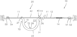
- FIG. 1 shows an embodiment of a lifeline 10 .
- a lifeline 10 comprises tension member 12 and a shock absorber 20 .
- FIG. 2 shows an embodiment of a shock absorber 20 .
- FIG. 3 shows an embodiment of a tension member 12 extending through an embodiment of a shock absorber 20 .
- a lifeline 10 comprises a tension member 12 arranged to extend between a first anchor 50 and a second anchor 52 .
- Anchors 50 , 52 are often provided on tall buildings, and a lifeline 10 can attach to the anchors 50 , 52 .
- a lifeline 10 comprises one or more carabiners 54 arranged to engage the anchors 50 , 52 .
- the tension member 12 can comprise any suitable tension member, such as metal, natural fibers, synthetic fibers, etc., and can comprise any suitable cross-sectional shape.
- a tension member 12 comprises a strap.
- a tension member 12 comprises a wire rope, for example comprising galvanized metal or stainless steel.
- a lifeline 10 comprises a tensioning device 14 arranged to adjust an amount of tension in the tension member 12 .
- Any suitable tensioning device 14 can be used, such as a turnbuckle, a ratcheting mechanism, come-along, etc.
- a shock absorber 20 comprises a body member 22 comprising a non-linear portion along its length.
- the shock absorber 20 engages the tension member 12 and causes the tension member to have a displaced portion 15 that is laterally displaced from a direct line extending between the anchors 50 , 52 .
- the shock absorber 20 is arranged to deform upon a sharp increase in the tension in the tension member 12 , for example as caused by the lifeline 10 catching a user during a fall. Desirably, deformation of the shock absorber 20 allows for an effective feed-out of the tension member 12 and reduces the impact and jerk experienced by a user that is caught by the lifeline 10 .
- the body member 22 of the shock absorber 20 comprises a tubular shape defining a lumen therethrough. In some embodiments, a sidewall of the body member 22 fully surrounds the lumen. In some embodiments, the tension member 12 extends through the lumen of the body member 22 .
- the body member 22 comprises curvature along its length. In some embodiments, the body member 22 comprises an angle, or multiple linear body portions arranged at an angle to one another. In some embodiments, the body member 22 comprises a first length portion extending nonparallel to a second length portion.
- the shock absorber 20 engages the tension member 12 at multiple locations. In some embodiments, the shock absorber 20 engages the tension member 12 at a first location 70 , a second location 72 and a third location 74 . In some embodiments, the first location 70 is oriented closest to the first anchor 50 and the third location 74 is oriented closest to the second anchor 52 . In some embodiments, the second location 72 is located along a length of the tension member 12 between the first location 70 and third location 74 . In some embodiments, the engagement at the second location 72 causes the tension member 12 to be laterally displaced from the axis 11 of the lifeline 10 .
- the body member 22 comprises a tube, and the tension member 12 is fully surrounded by the tube between the first location 70 and the third location 74 .
- the body member 22 comprises a non-tubular shape and is arranged to engage the tension member 12 at the locations 70 , 72 , 74 in any suitable way.
- the body member 22 can comprise loops, hooks, clamps, fasteners or any other suitable engagement mechanism, or combination thereof, to engage the body member 22 and the tension member 12 at the locations 70 , 72 , 74 .
- the body member 22 comprises a first portion 24 and a second portion 26 .
- the first and second portions 24 , 26 comprise ends of the body member 22 .
- a distance between the first portion 24 and second portion 26 is less than the length of a path between the first portion 24 and second portion 26 as traversed along the body member 22 .
- each portion 24 , 26 contacts the tension member 12 .
- the first portion 24 of the body member 22 comprises the first location 70 of engagement between the shock absorber 20 and tension member 12 .
- the second portion 26 of the body member 22 comprises the third location 74 of engagement between the shock absorber 20 and tension member 12 .
- the body member 22 comprises a third portion 28 , and the third portion 28 contacts the tension member 12 .
- the third portion 28 contacts the tension member 12 at a location between the first portion 24 and second portion 26 along the length of the tension member 12 .
- the third portion 20 of the body member 22 comprises the second location 72 of engagement between the shock absorber 20 and tension member 12 .
- the first location 70 and third location 74 are each located near the ordinary axis 11 of the lifeline 10 , and the second location 72 is laterally displaced from the axis 11 . In some embodiments, a distance between the lifeline axis 11 and the second location 72 is substantially greater than a distance between the lifeline axis 11 and the first location 70 or the third location 74 .
- the shock absorber 20 is constructed and arranged such that higher amounts of tension in the tension member 12 cause the body member 22 to deform under load and cause the distance between the first portion 24 and second portion 26 to increase.
- the body member 22 can have any suitable profile and any suitable cross-sectional shape.
- the body member 22 comprises a tube comprising a hollow interior, and the tension member 12 extends through the hollow interior.
- the body member 22 forms a U-shape. In some embodiments, a longitudinal axis of the body member 22 forms a U-shape.
- the shock absorber 20 defines a cavity 23 and the tension member 12 extends around the cavity 23 .
- a shape of the cavity 23 will change as the body member 22 deforms in response to applied loads.
- the shock absorber 20 comprises a nominal condition comprising a nominal shape.
- the shock absorber 20 will assume a deformed shape in response to a high-tension condition, for example caused by a fall event.
- the nominal shape is intended to encompass ordinary usage and exclude fall events.
- the nominal shape is intended to include smaller elastic deformations that occur when the lifeline 10 is loaded under ordinary usage that excludes high-tension conditions.
- the shock absorber 20 assumes the deformed shape under a high-tension condition, for example caused by a fall event.
- the deformed shape comprises a plastically deformed shape when compared to the nominal shape.
- FIG. 4 shows an embodiment of a shock absorber 20 and illustrates examples of a nominal shape 76 and a deformed shape 78 .
- the cavity 23 changes shape as the shock absorber 20 is deformed.
- a first dimension of the cavity 23 e.g. width
- a second dimension of the cavity 23 e.g. height
- the shock absorber 20 comprises a deformation gauge 40 .
- the deformation gauge 40 is arranged to indicate proper loading and/or overloading of tension on the tension member 12 .
- the deformation gauge 40 can indicate whether the body member 22 has experienced plastic deformation as compared to an original nominal shape, for example when the tension member 12 is not loaded.
- the deformation gauge 40 is arranged to indicate that the shock absorber 20 should not be used due to plastic deformation from prior loading.
- a deformation gauge 40 comprises a rod 42 that extends between the first portion 24 and the second portion 26 of the body member 22 .
- the rod 42 is pivotably attached to the body member 22 .
- the deformation gauge 40 comprises a receiver 44 arranged to receive the rod 42 or indicate a relative position of the rod 42 .
- the receiver 44 comprises a loop of material defining a cavity, and the rod extends through the cavity.
- the rod 44 comprises markings, such as hash markings, arranged to gauge deformation of the body member 22 .
- the rod 42 extends to and contacts the receiver 44 when the shock absorber 20 comprises its nominal shape 76 . In some embodiments, the rod 42 extends toward but does not reach the receiver 44 when the shock absorber 20 comprises its deformed shape 78 .
- the body member 22 comprises a first length portion 30 , a second length portion 32 and a third length portion 34 .
- the first length portion 30 comprises curvature.
- curvature of the first length portion 30 comprises a first radius of curvature r 1 .
- the second length portion 32 comprises curvature.
- curvature of the second length portion 32 comprises a second radius of curvature r 2 .
- a first inflection 36 is located between the first length portion 30 and the second length portion 32 .
- the third length portion 34 comprises curvature.
- curvature of the third length portion 34 comprises a third radius of curvature r 3 .
- a second inflection 38 is located between the second length portion 32 and the third length portion 34 .
- the second radius of curvature r 2 is greater than the first radius of curvature r 1 or the third radius of curvature r 3 . In some embodiments, first radius of curvature r 1 is equal to the third radius of curvature r 3 .
- FIG. 5 shows another embodiment of a lifeline 10 .
- FIG. 6 shows components of an embodiment of a lifeline 10 .
- a first anchor 50 and a second anchor 52 are attached to a supporting structure, such as a building.
- the anchors 50 , 52 can be attached using any suitable method, such as fasteners 56 , welding, etc.
- the supporting structure comprises one or more intermediate anchors 51 located between the first anchor 50 and the second anchor 52 .
- the tension member 12 engages the first anchor 50 .
- a tensioning device 14 engages the first anchor 50 and the tension member 12 engages the tensioning device 14 .
- the tensioning device 14 comprises a turnbuckle.
- the tension member 12 is attached to the tensioning device 14 , or alternatively the first anchor 50 , by extending through a loop 53 and folding back on itself to form an end loop 13 .
- a thimble 62 is used to guide the tension member and form the end loop 13 .
- clips 58 are used to secure the tension member 12 to itself.
- a clip 58 comprises a wire rope clip.
- the tension member 12 extends toward the shock absorber 20 along the axis 11 of the lifeline 10 .
- the tension member 12 follows a non-linear path as it traverses the shock absorber 20 , then extends away from the shock absorber 20 along the axis 11 of the lifeline 10 .
- the tension member 12 extends through any suitable number of intermediate anchors 51 along its length.
- the tension member 12 forms another end loop 13 at its second end.
- the second end loop 13 can also comprise a thimble 62 , and the second end loop 13 can be formed by folding the tension member 12 back upon itself and using one or more clips 58 .
- the second end loop 13 is arranged to engage the second anchor 52 .
- any dependent claim which follows should be taken as alternatively written in a multiple dependent form from all prior claims which possess all antecedents referenced in such dependent claim if such multiple dependent format is an accepted format within the jurisdiction (e.g. each claim depending directly from claim 1 should be alternatively taken as depending from all previous claims).
- each claim depending directly from claim 1 should be alternatively taken as depending from all previous claims.
- the following dependent claims should each be also taken as alternatively written in each singly dependent claim format which creates a dependency from a prior antecedent-possessing claim other than the specific claim listed in such dependent claim below.
Landscapes
- Engineering & Computer Science (AREA)
- Architecture (AREA)
- Health & Medical Sciences (AREA)
- General Health & Medical Sciences (AREA)
- Business, Economics & Management (AREA)
- Emergency Management (AREA)
- Mechanical Engineering (AREA)
- Civil Engineering (AREA)
- Structural Engineering (AREA)
- Emergency Lowering Means (AREA)
- Vibration Dampers (AREA)
Abstract
Description
Claims (20)
Priority Applications (1)
| Application Number | Priority Date | Filing Date | Title |
|---|---|---|---|
| US16/012,725 US10695595B2 (en) | 2017-06-16 | 2018-06-19 | Safety line shock absorber |
Applications Claiming Priority (2)
| Application Number | Priority Date | Filing Date | Title |
|---|---|---|---|
| US201762521261P | 2017-06-16 | 2017-06-16 | |
| US16/012,725 US10695595B2 (en) | 2017-06-16 | 2018-06-19 | Safety line shock absorber |
Publications (2)
| Publication Number | Publication Date |
|---|---|
| US20190143159A1 US20190143159A1 (en) | 2019-05-16 |
| US10695595B2 true US10695595B2 (en) | 2020-06-30 |
Family
ID=66432966
Family Applications (1)
| Application Number | Title | Priority Date | Filing Date |
|---|---|---|---|
| US16/012,725 Active US10695595B2 (en) | 2017-06-16 | 2018-06-19 | Safety line shock absorber |
Country Status (1)
| Country | Link |
|---|---|
| US (1) | US10695595B2 (en) |
Cited By (2)
| Publication number | Priority date | Publication date | Assignee | Title |
|---|---|---|---|---|
| US20220355135A1 (en) * | 2021-05-08 | 2022-11-10 | Alexander Andrew, Inc. Dba Falltech | Temporary cable horizontal lifeline kits, systems and methods |
| RU2824030C1 (en) * | 2023-12-28 | 2024-07-31 | Акционерное общество "Научно-производственная корпорация "Уралвагонзавод" имени Ф.Э. Дзержинского" | Anchor device for individual fall protection when working at height |
Families Citing this family (9)
| Publication number | Priority date | Publication date | Assignee | Title |
|---|---|---|---|---|
| EP3895138B1 (en) | 2019-01-14 | 2025-10-08 | MSA Technology, LLC | Fall protection compliance system and method |
| US12429494B2 (en) | 2019-01-14 | 2025-09-30 | Msa Technology, Llc | Fall protection compliance system and method |
| US12412464B2 (en) | 2019-01-14 | 2025-09-09 | Msa Technology, Llc | Fall protection compliance system and method |
| US10987983B1 (en) * | 2020-10-29 | 2021-04-27 | King Abdulaziz University | Dampening safety device able to attach to a soft towline and methods for use |
| US11795713B2 (en) * | 2022-01-18 | 2023-10-24 | Tie Down, Inc. | Fall protection system |
| US11753836B2 (en) * | 2022-01-18 | 2023-09-12 | Tie Down, Inc. | Fall protection system |
| USD1015865S1 (en) | 2022-12-08 | 2024-02-27 | Charles J. Mackarvich | Corner guard |
| US12325113B2 (en) | 2023-11-14 | 2025-06-10 | Charles J. Mackarvich | Clamp assembly for fall protection reinforcement post |
| US12359452B1 (en) | 2024-01-09 | 2025-07-15 | Tie Down, Inc. | Fall protection system and guardrail post assembly therefor |
Citations (2)
| Publication number | Priority date | Publication date | Assignee | Title |
|---|---|---|---|---|
| US6014794A (en) * | 1999-03-25 | 2000-01-18 | Mc Coy; Patrick M. | Reinforced bungee cord tie down |
| US7454818B1 (en) * | 2005-06-21 | 2008-11-25 | Backman Iii Carl A | Elastic tie down |
-
2018
- 2018-06-19 US US16/012,725 patent/US10695595B2/en active Active
Patent Citations (2)
| Publication number | Priority date | Publication date | Assignee | Title |
|---|---|---|---|---|
| US6014794A (en) * | 1999-03-25 | 2000-01-18 | Mc Coy; Patrick M. | Reinforced bungee cord tie down |
| US7454818B1 (en) * | 2005-06-21 | 2008-11-25 | Backman Iii Carl A | Elastic tie down |
Cited By (2)
| Publication number | Priority date | Publication date | Assignee | Title |
|---|---|---|---|---|
| US20220355135A1 (en) * | 2021-05-08 | 2022-11-10 | Alexander Andrew, Inc. Dba Falltech | Temporary cable horizontal lifeline kits, systems and methods |
| RU2824030C1 (en) * | 2023-12-28 | 2024-07-31 | Акционерное общество "Научно-производственная корпорация "Уралвагонзавод" имени Ф.Э. Дзержинского" | Anchor device for individual fall protection when working at height |
Also Published As
| Publication number | Publication date |
|---|---|
| US20190143159A1 (en) | 2019-05-16 |
Similar Documents
| Publication | Publication Date | Title |
|---|---|---|
| US10695595B2 (en) | Safety line shock absorber | |
| US5332071A (en) | Shock absorber for safety cable system | |
| JP5054742B2 (en) | Rock fall protection fence | |
| JP6906100B2 (en) | Net and / or rope structure brake | |
| US7357222B2 (en) | Energy absorber for horizontal lifeline system | |
| JP5764190B2 (en) | Energy absorber, horizontal lifeline system, and method of providing incremental load using energy absorber | |
| CA2690038A1 (en) | Dynamic stabilization connecting member with pre-tensioned solid core | |
| US10112078B1 (en) | Step assembly with fall arrest capability including removable step | |
| CA2765986A1 (en) | Apparatus for receiving shock loading | |
| JP5919098B2 (en) | Protective fence | |
| US7093327B2 (en) | Strap fastener set | |
| US6581725B2 (en) | Method to reduce horizontal lifeline tension and extension during fall arrest | |
| US20150158479A1 (en) | Spring-style air brake hose support | |
| JP5520366B2 (en) | A device that absorbs the kinetic energy of a moving body | |
| JP2004522477A (en) | Terminal equipment for horizontal lifeline cables | |
| US20060144640A1 (en) | Method for producing a ring for a safety net, especially for rockfall or avalanche baffle works, and also a safety net | |
| WO2014202612A2 (en) | Energy absorber | |
| AU2006251140B2 (en) | Tensioning device for safety line with damping device | |
| KR102148450B1 (en) | Personal anchorage connector and method of preventing worker from dropping by using the same | |
| CN105134876B (en) | Tension device | |
| CN110420408A (en) | A kind of high-altitude working safety dragline component and high-altitude working safety guide cable system | |
| RU159198U1 (en) | DEVICE FOR FASTENING CARGO ON VEHICLE | |
| AU697769B2 (en) | A static line shock absorber | |
| RU2824030C1 (en) | Anchor device for individual fall protection when working at height | |
| AU2013100199A4 (en) | Improved restraint for hoses or the like |
Legal Events
| Date | Code | Title | Description |
|---|---|---|---|
| FEPP | Fee payment procedure |
Free format text: ENTITY STATUS SET TO UNDISCOUNTED (ORIGINAL EVENT CODE: BIG.); ENTITY STATUS OF PATENT OWNER: SMALL ENTITY |
|
| FEPP | Fee payment procedure |
Free format text: ENTITY STATUS SET TO SMALL (ORIGINAL EVENT CODE: SMAL); ENTITY STATUS OF PATENT OWNER: SMALL ENTITY |
|
| AS | Assignment |
Owner name: ENGINEERED SUPPLY L.L.C., MINNESOTA Free format text: ASSIGNMENT OF ASSIGNORS INTEREST;ASSIGNOR:GRANT, ARLEN PAUL;REEL/FRAME:046737/0448 Effective date: 20180619 |
|
| STPP | Information on status: patent application and granting procedure in general |
Free format text: DOCKETED NEW CASE - READY FOR EXAMINATION |
|
| FEPP | Fee payment procedure |
Free format text: PETITION RELATED TO MAINTENANCE FEES GRANTED (ORIGINAL EVENT CODE: PTGR); ENTITY STATUS OF PATENT OWNER: SMALL ENTITY |
|
| STPP | Information on status: patent application and granting procedure in general |
Free format text: NON FINAL ACTION MAILED |
|
| STPP | Information on status: patent application and granting procedure in general |
Free format text: RESPONSE TO NON-FINAL OFFICE ACTION ENTERED AND FORWARDED TO EXAMINER |
|
| STPP | Information on status: patent application and granting procedure in general |
Free format text: NOTICE OF ALLOWANCE MAILED -- APPLICATION RECEIVED IN OFFICE OF PUBLICATIONS |
|
| STPP | Information on status: patent application and granting procedure in general |
Free format text: PUBLICATIONS -- ISSUE FEE PAYMENT VERIFIED |
|
| STCF | Information on status: patent grant |
Free format text: PATENTED CASE |
|
| MAFP | Maintenance fee payment |
Free format text: PAYMENT OF MAINTENANCE FEE, 4TH YR, SMALL ENTITY (ORIGINAL EVENT CODE: M2551); ENTITY STATUS OF PATENT OWNER: SMALL ENTITY Year of fee payment: 4 |