US1069557A - Flexible harrow. - Google Patents
Flexible harrow. Download PDFInfo
- Publication number
- US1069557A US1069557A US63982411A US1911639824A US1069557A US 1069557 A US1069557 A US 1069557A US 63982411 A US63982411 A US 63982411A US 1911639824 A US1911639824 A US 1911639824A US 1069557 A US1069557 A US 1069557A
- Authority
- US
- United States
- Prior art keywords
- sections
- teeth
- series
- frame
- bars
- Prior art date
- Legal status (The legal status is an assumption and is not a legal conclusion. Google has not performed a legal analysis and makes no representation as to the accuracy of the status listed.)
- Expired - Lifetime
Links
- 101100177165 Caenorhabditis elegans har-1 gene Proteins 0.000 description 1
- RYGMFSIKBFXOCR-UHFFFAOYSA-N Copper Chemical compound [Cu] RYGMFSIKBFXOCR-UHFFFAOYSA-N 0.000 description 1
- 235000016936 Dendrocalamus strictus Nutrition 0.000 description 1
- XDXHAEQXIBQUEZ-UHFFFAOYSA-N Ropinirole hydrochloride Chemical compound Cl.CCCN(CCC)CCC1=CC=CC2=C1CC(=O)N2 XDXHAEQXIBQUEZ-UHFFFAOYSA-N 0.000 description 1
- 238000009499 grossing Methods 0.000 description 1
- 239000002184 metal Substances 0.000 description 1
- 230000000284 resting effect Effects 0.000 description 1
- 230000002441 reversible effect Effects 0.000 description 1
- 239000002689 soil Substances 0.000 description 1
Images

Classifications
-
- A—HUMAN NECESSITIES
- A01—AGRICULTURE; FORESTRY; ANIMAL HUSBANDRY; HUNTING; TRAPPING; FISHING
- A01B—SOIL WORKING IN AGRICULTURE OR FORESTRY; PARTS, DETAILS, OR ACCESSORIES OF AGRICULTURAL MACHINES OR IMPLEMENTS, IN GENERAL
- A01B19/00—Harrows with non-rotating tools
- A01B19/08—Harrows with non-rotating tools with link network supporting tooth-like tools
Definitions
- My invention relates to new and useful improvements in' harrows and my object is to provide a harrow in which the frame.
- a further object is to provide stay b ars at the ends of the harrow to hold the frame sections in proper ⁇ alinement, Y.
- a further object is to provide detachable teeth forthe harrow, and, a still further object is to so arrange the teeth as tov adapt them for deep or shallow cultivation.
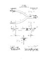
- Figure 1 is a top plan view of the harrow complete.
- F ig. 2 is an enlarged top plan view of one of the sections of the' frame.
- F ig. 3 isan edge elevation thereof, and, ,F ig. '4 is a sectional view as seen on line 4 4 Fig. :3. 1
- each section comprising a pair of bars2 and'3, the forward ends'bf which are placed parallel with each other and secured together by means of rivets, bolts, or the like 4, whilethe rear portions of said bars arespread apart and describe an arc of a circle.
- the bars 2 and 3 are preferably angular shaped in cross section the top or horizontal extension thereof having slots 5 therethrough, through which extend the harrow teeth 6, said teeth, when extended' through the slots, resting against the-vertical portion of the bars.
- the teeth 6. are secured to the 'vertical portions of the bars by means The ends of the teeth are cut at. an angle, the longer face of'. the teeth bei-ngtowa-rd the front of the har-row .and by placing the holes throughthe teeth for the bolts 7 nearer one end of lthe teeth than the other, the
- each succeeding series of frame sections vis attached to the preceding sections by means of chains or the like 8, there being two chains at the Vforward end ofeach framesection, one of which is enga ed with oneof the bars of the forward rame. section and the other chain to the rear'end of one of the bars' of thenext frame section in thevseries, and by frame .sections will be properly-guided with tion will be 'free toriseandwfall in order to ground.
- tions are attached to cross bars 9 and l0, through the medium of chain sections: 11 and 12 respectively, said bars serving to properly spread the frame sections and prevent the same from becoming entangled. or upset when turning the barrow.
- the frame sections atthe. ends of the larger series are properly guded'by providing elongated chain sections'l and 14, the chain sections 13 extending forwardly and engaging the cross bar 9 whlle the chain sections 14 extend from the forward. ends of the two outermost frame Asectionsof the rear series to the rear ends of the outermost bars of rthe two .outside frame .members of the Patented Aug. 5,1913, i
- That claim is; Y Y f A 'narrow section-substantially Y-sheped'v in form and consisting .of companion angle ⁇ Loonse? bers ⁇ hdv'ng depending flanges secured in contacting :felation tI-o each other and .pro riding cuttlnfr edge portions and horizonleon'tactng Sport-ions ofisaid bars and by the ends thereof, said teeth being secured to said tally dispose flanges .teeth carried .by th.,
Landscapes
- Life Sciences & Earth Sciences (AREA)
- Engineering & Computer Science (AREA)
- Mechanical Engineering (AREA)
- Soil Sciences (AREA)
- Environmental Sciences (AREA)
- Soil Working Implements (AREA)
Description
W. LUTZF..
FLEXIBLE NARROW.
APPLwArmN rlmgn JULY 21,1911,
Patented Aug'. 5, 1913* 2 SHEETS-SHEET 1.
lforneys fha??-w Y W. LUTZE.
FLEXIBLE HARROW. APPLICATION FILED JULY 21, 1911.
Patented Aug. 5, 1913.
2 SHEBTIHIHEBT a.
lllllllllm WV kw Vaud I do hereby declare` the following to.
UNITED STATES PATENT onirica.
WILLIAM LUTZE, 0F
HoIQYoKE, COLORADO.
FLEXIBLE BARR-ow.
Specification of Letters Patent.
Application led July 21, 1911. Serial No. 639,824.
citizen of the United States, residing at` Holyoke, in the county of Phillips and YState ofColorado, have invented certain new and useful Improvements in Flexible Harrows;
be a full, clear, and exact description of the invention, such as will enable others skilled in the art to which it appertains' to make and use the same.
My invention relates to new and useful improvements in' harrows and my object is to provide a harrow in which the frame.
portions will be flexible.
A further object is to provide stay b ars at the ends of the harrow to hold the frame sections in proper` alinement, Y.
A further object is to provide detachable teeth forthe harrow, and, a still further object is to so arrange the teeth as tov adapt them for deep or shallow cultivation.
Other objects and advantages will hereinafter be set forth and pointed out in the specification. l In the accompanying drawmgs, which are made a part of this application, Figure 1 is a top plan view of the harrow complete. F ig. 2 is an enlarged top plan view of one of the sections of the' frame. F ig. 3 isan edge elevation thereof, and, ,F ig. '4 is a sectional view as seen on line 4 4 Fig. :3. 1
Referring to the drawings in whichA simi'- lar` reference numerals designate corresponding parts throughoutthe several views,
1 indicatesthe frame sections ofthe har-1 row, -which sections are preferably arranged in series, the rst series comprlslng preferably four sections, the second series live sections, the third series four sections, and
' so on until the fullcomplement of sections have been arranged, each section comprising a pair of bars2 and'3, the forward ends'bf which are placed parallel with each other and secured together by means of rivets, bolts, or the like 4, whilethe rear portions of said bars arespread apart and describe an arc of a circle.
The bars 2 and 3 are preferably angular shaped in cross section the top or horizontal extension thereof having slots 5 therethrough, through which extend the harrow teeth 6, said teeth, when extended' through the slots, resting against the-vertical portion of the bars. The teeth 6. are secured to the 'vertical portions of the bars by means The ends of the teeth are cut at. an angle, the longer face of'. the teeth bei-ngtowa-rd the front of the har-row .and by placing the holes throughthe teeth for the bolts 7 nearer one end of lthe teeth than the other, the
^ and one at the rear end of each of the bars so that the forward toothwillengage the vs oil at a point substantially midway between the path of the two rear teeth and by placing the second series of teeth so that the forlward end thereof will travel in a path at a point substantially midway between -each pair of the preceding series of sections the soil will be thoroughly agitated. Each succeeding series of frame sections vis attached to the preceding sections by means of chains or the like 8, there being two chains at the Vforward end ofeach framesection, one of which is enga ed with oneof the bars of the forward rame. section and the other chain to the rear'end of one of the bars' of thenext frame section in thevseries, and by frame .sections will be properly-guided with tion will be 'free toriseandwfall in order to ground.
tions are attached to cross bars 9 and l0, through the medium of chain sections: 11 and 12 respectively, said bars serving to properly spread the frame sections and prevent the same from becoming entangled. or upset when turning the barrow. As each in number the frame sections atthe. ends of the larger series are properly guded'by providing elongated chain sections'l and 14, the chain sections 13 extending forwardly and engaging the cross bar 9 whlle the chain sections 14 extend from the forward. ends of the two outermost frame Asectionsof the rear series to the rear ends of the outermost bars of rthe two .outside frame .members of the Patented Aug. 5,1913, i
Lgreater portions of said teeth will projectl The forward and realli series of frame sec-- larger series precedingrearmost series.l
of bolts 7, one bolt used for-,each tooth. f
is preferably (thus spreading the ,fchainslfand 'attaching them. in lthe manner shown; -thegvairious '90 respect'to'each `other while-each frame secaccommodate itself .to `the uneir'renixessl of the alterna te series of frame sections is increased lf e deep culti 1.
tion is desiredthe Aharrow'v isf positioned with 't'zie'longer ends -of the -ievh lm gecziing drmfnwardly, but; Should a 4fniijtlier vbe seen that as all lthe parl-s of the nnirrow re constructed of metal they will be practically indestructible from use, and it*A will likewise be see-n'that'the-teeth may be quickly removedend applied to 'use as. but` one bolt 'is requi ed for" holding the same in posit-ion.V
That claim is; Y Y f A 'narrow section-substantially Y-sheped'v in form and consisting .of companion angle `Loonse? bers` hdv'ng depending flanges secured in contacting :felation tI-o each other and .pro riding cuttlnfr edge portions and horizonleon'tactng Sport-ions ofisaid bars and by the ends thereof, said teeth being secured to said tally dispose flanges .teeth carried .by th.,
bans nearerl vtheir upper ends-*than theirl ;v
ing means.
In testimony rwhereof 'I have signed my horizontal flanges V.will serve'ns smoothing means and the verhaal flanges as, sod break# name to this specification inthe lpresence of WILLIAMLLUQZF.. 4
lower' endsg'and 'saidsection being reversible Y Copies lofthis patent; mai be obtained for ive cvents'each, by'. addressing the Commissioner` of Patents,
` u' Washington, DCJ' l
Priority Applications (1)
| Application Number | Priority Date | Filing Date | Title |
|---|---|---|---|
| US63982411A US1069557A (en) | 1911-07-21 | 1911-07-21 | Flexible harrow. |
Applications Claiming Priority (1)
| Application Number | Priority Date | Filing Date | Title |
|---|---|---|---|
| US63982411A US1069557A (en) | 1911-07-21 | 1911-07-21 | Flexible harrow. |
Publications (1)
| Publication Number | Publication Date |
|---|---|
| US1069557A true US1069557A (en) | 1913-08-05 |
Family
ID=3137794
Family Applications (1)
| Application Number | Title | Priority Date | Filing Date |
|---|---|---|---|
| US63982411A Expired - Lifetime US1069557A (en) | 1911-07-21 | 1911-07-21 | Flexible harrow. |
Country Status (1)
| Country | Link |
|---|---|
| US (1) | US1069557A (en) |
Cited By (3)
| Publication number | Priority date | Publication date | Assignee | Title |
|---|---|---|---|---|
| DE2505936A1 (en) * | 1975-02-13 | 1976-08-26 | Sen Georg Weigl | SCHMIEGEEGGE |
| DE3221967A1 (en) * | 1982-06-11 | 1983-12-15 | Max 8200 Rosenheim Haas | Bevelling harrow |
| DE3309938A1 (en) * | 1983-03-19 | 1984-09-20 | Max 8200 Rosenheim Haas | TOW BAR FOR EGGE |
-
1911
- 1911-07-21 US US63982411A patent/US1069557A/en not_active Expired - Lifetime
Cited By (3)
| Publication number | Priority date | Publication date | Assignee | Title |
|---|---|---|---|---|
| DE2505936A1 (en) * | 1975-02-13 | 1976-08-26 | Sen Georg Weigl | SCHMIEGEEGGE |
| DE3221967A1 (en) * | 1982-06-11 | 1983-12-15 | Max 8200 Rosenheim Haas | Bevelling harrow |
| DE3309938A1 (en) * | 1983-03-19 | 1984-09-20 | Max 8200 Rosenheim Haas | TOW BAR FOR EGGE |
Similar Documents
| Publication | Publication Date | Title |
|---|---|---|
| US1069557A (en) | Flexible harrow. | |
| US4725A (en) | Improvement in cultivators | |
| US463933A (en) | Attachment for cultivators | |
| US1008708A (en) | Rotary cultivator. | |
| US377781A (en) | Cultivator and scraper combined | |
| US203053A (en) | Improvement in harrow and cultivator combined | |
| US602430A (en) | Weed-cutter attachment for cultivators | |
| US352703A (en) | Cultivator | |
| US7770A (en) | Improvement in seed-planters | |
| US145862A (en) | Improvement in plows | |
| US772724A (en) | Stone-gathering machine. | |
| US928487A (en) | Cultivator. | |
| US944770A (en) | Spring-tooth cultivator. | |
| US1079752A (en) | Harrrow. | |
| US841922A (en) | Harrow. | |
| US900004A (en) | Cultivating implement. | |
| US1805850A (en) | Agricultural implement | |
| US665751A (en) | Harrow. | |
| US1651086A (en) | Harrow | |
| US817999A (en) | Land-scraper. | |
| US285318A (en) | Cultivator | |
| US688877A (en) | Cultivator fender attachment. | |
| US263978A (en) | Combined scraper and harrow | |
| US245360A (en) | Cultivator | |
| US368894A (en) | Lister-cultivator |