US1069481A - Calculating-machine. - Google Patents
Calculating-machine. Download PDFInfo
- Publication number
- US1069481A US1069481A US50783909A US1909507839A US1069481A US 1069481 A US1069481 A US 1069481A US 50783909 A US50783909 A US 50783909A US 1909507839 A US1909507839 A US 1909507839A US 1069481 A US1069481 A US 1069481A
- Authority
- US
- United States
- Prior art keywords
- gears
- registering
- mechanisms
- shaft
- setting
- Prior art date
- Legal status (The legal status is an assumption and is not a legal conclusion. Google has not performed a legal analysis and makes no representation as to the accuracy of the status listed.)
- Expired - Lifetime
Links
Images


Classifications
-
- G—PHYSICS
- G06—COMPUTING OR CALCULATING; COUNTING
- G06C—DIGITAL COMPUTERS IN WHICH ALL THE COMPUTATION IS EFFECTED MECHANICALLY
- G06C23/00—Driving mechanisms for functional elements
- G06C23/04—Driving mechanisms for functional elements of pin carriage, e.g. for step-by-step movement
Definitions
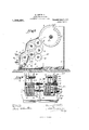
- Figure 1 is a front ele- Va-tion of the machine
- Fig. 2 is a plan or top View 'ofthe same, the cover being re- -moved
- Fig. 3 is a vertical cross-section taken-onthe line A-rA of Figs. 1 and 2
- FIGs. 12 and 13 are detail views of thetens-transfer or carrying mechauisu'i of the second registering mechanism, Fig. 11, is a vertical crosssection. of a machine showing a modification of the mechanism illustrated in Figs. 1 to Specification of Letters Patent. Application filed July 15, 1909. Serial No. 507,839.
- the calculating-mechanism is lVithin the lower part of the-latter a carriage 2 is guided in suitable grooves of the base plate of the machine.
- handles 4 projecting through slots 3 of the casing 1 the numbers are set on adjusting disks 5, and by turning a crank they are transmitted through the intermediary of gears G mounted on shaft 6 to the registering mechanism '7 comprising number wheels 7 and pinions 7
- Belowthe registering mechanism 7 I provide a second registering mechanism 8 comprising number-wheels S and pinions 8 which are adapted to be operated from the gears 6 through-the intern'iediary of trains of gears 9 10 and 11 carried by sha ft-s 9 15 and 12 respectively.
- the shafts 12 and 15 are slidably SIIPPOltGd in the side walls of the carriage 2, as indicated in Figs. 6 and 9.
- the shaft (36.0f the iuunbcr-wheels S carries a rocking lever 13 which with one of its ends loosely engages in a groove of the shaft 12 and with its other end projects Fig. 15, is .a fragmentary frontview'of I through a slot 71 of the casing '1, where it.
- the longitudinally shiftable' shaft 15 carrying the gears 10 projects through a hole in the side wall of the asing 2, and its projecting end is engaged by a shift lever 17 having its fulcrum at 16 and 'irovided with a handle 18.
- a shift lever 17 having its fulcrum at 16 and 'irovided with a handle 18.
- the figure wheels 7 and S are provided at their peripheries with numerical characters from 1 to 9 and the O Sign, and if the-wheels are in the position shown in Fig. 3, the numbers transmitted thereto appear in ascending succession in both registering mechanisms 7 and 8. If, however, the shaft 12 is raised by depressing the key. l t, the gears 11 are disengaged from the gears 10 and brought in direct engagen'ient with the of the registering mecha nisms 7 and 8. Thereby the direction of rotation of the number wheels .8 is reversed, so that the numbers appear in descending succession, and the number wheels 8 register a subtraction of the number which on the number wheels 7 is registered as an addition.
- a key 21 is fulcrumed at 19, which with its key carrying arm projects through a slot 72 in the casing formed with a nose 22 providing a lock for the said shaft.
- the levers 13 and 20 are connected with each other by a spring 23. If the shaft 12 is raised, the nose 22, under the action of the spring 23, engages the shaft 12 at its lower side, so as to lock the same in its raised position, as shown in Fig. 1. To disengage the gear 11 from the pinion 7 the key 21 is depressed, whereby the nose 22 is retracted from below the shaft 12, and the latter drops'into its original position under the action of the spring 23.
- the tens-transfer or carrying mechanism for the number wheels 7 can be'const-ructed 1n any known or preferred way.
- the number wheels 8 require independent carrying means, and these carrying means must be operated after thecarrying operation in the number wheels 7 has been com pleted.
- a segment or disk 24 having teeth about part of its circumference. is mounted on the shaft 5 carrying the adjusting disks 5. (Figs. 2, 10 and 11.) 55' By means of the said toothed segment spur gears 25 and 26-mounted on the casing -1 can be rotated.
- gear 26 there is an elongated toothed gearing 27exten'ding over the whole length of the adjusting device.
- gears 28, 29 and 30 are mounted which are in engagement with one another.
- the spur gears 28 and 26 both mesh with the-elongated gear 27.
- The-gear 30f meshes with a spur gear 32 keyed to a shaft 31 located below the num- 1, and at its other end is wheels.
- the other part of the plate 12 is formed with two eyes and 16 which ,embrace the ends of the shafts 6? and (it; of the number wheels 7 and 'S, which ends project through the sidewall of the carriage. lly a spring at? the said eyes it" and ell; are normally held away from the sit'le-wall of the carriage, while the end 43 of the plate is forced toward the same.
- the shifting movement: of the shaft'15 is not interfercd with. so that the said shaft can be so adjusted by the lever 17, that the gears 10 are either in or out of engagement with the gears 9 and 1.1. as described above.
- the crank it or 55 is turned, the end 50 of the pins 4-8 or it), as the case may be, by the displace ment of the shaft by means of the said pin- -l8 or 15), will ride on the margin of the eye 15 or 16, so that the latter is forced toward the wall of the casing.
- the opposite end 43 is removed from the side wall of the carriage, and it carries along the shaft- 15 through the intermediary of the sleeve l i, so that the gears 10 are shifted laterally and thrown out of engagement with the gears 9 and 11.
- a shaft 61 In front of the registering mechanism 108 a shaft 61 is located which carries gears 61 partly projecting through slots 61- ofthe casing. By the said gears the wheels 108 can be directly turned and adjustedto showa certain number in the registering mechanism 8.
- a product can be subtracted from aof the setting operation and operative in both directions to transmit the values set onthesetting mechanism to said registering mecha'nisms', and'means to throw one of said registermg, mechanisms out ofcooperation with the setting mechanism.
- a setting disk having a plurality (Sf-normally inoperative teethfand means to move any number of said'te'eth into operative position, of-a plurality of registering mechanisms adapted to be operated upon rotation of said diskby the operative teeth, means operative in both directions to rotate said disk, and means to throw one of said i'registering mechanisms out of cooperation withflthe'teeth of said setting disk.
- the coibination with the 'settingir'iiechanism adapted to havelvalues setthereon, of a plurality of registering mechanisms means independent of the setting operationand operative both.
- IQQIn a calculating machine,'the combination with the settingmechanism adapted to have values set thereon, of two registering mechanisms, an operative connection between said setting mechanism and one of said registering mechanisms, two trains of gears of difierent numbers of gears adapted to connect said setting mechanism and second registering mechanism, means independent of the setting. operation to transmit the values set on the setting mechanism through the intermediary of sai'doperative iconnection'and trams of gearsfto said registering mechanisms, and means to throw either? one of said gears into cooperation with said'second setting mechanism.
- the combination with the setting mechanism adapted- .to have values set thereon, of a plurality of registering mechanisms,means independent of the setting operation to transmit the [alues set ⁇ in the setting mechanism to said registering mechanisms, resetting devices for each of said registering mechanisms and operable independently of said setting mechanlsm, and means to throw one of said registering mechanisms out of co'ciper'ation with the setting mechanism.
- pins being mounted within'slots made in s'aid shaft and adapted-to rest within one .oftwo notches provided at the bottom of each of said slots, means on said number wheels adapted to shift the pins into en gagement with the pinions of the number wheelsof-the next higher denomination, and means to remove the pins into their normal positions.
- a carryingmechanjsm for the registering mechanism com-' prlsing a rotary shaft extending longitudinally of-and adjacent to the number wheels and pinions of said registering mechanism, shiftablepins carried by said shaft, means on said number wheels adapted to shift the pins into engagement with the pinions of the number wheels of the next higher denomina tion, and a rotary shaft extending parallel and adjacent to said first named shaft.
- the combi-' nation with the setting mechanism, and the registering mechanism of a carrying mechanism for the registering mechanism comprising a rotary shaft extending longitudinally of and adjacent to the number wheels and pinions of said registering mechanism, shiftable' pins carried by said shaft, said pins being mounted within slots made in said shaft and adapted to rest within one 'of two notches provided at the bottom of. each of said slots, means on said number-wheels adapted to shift the pins into engagement with the pinions of the number wheels of the.
Landscapes
- Engineering & Computer Science (AREA)
- Physics & Mathematics (AREA)
- Computer Hardware Design (AREA)
- Computing Systems (AREA)
- General Physics & Mathematics (AREA)
- Theoretical Computer Science (AREA)
- Structure Of Transmissions (AREA)
Description
B. SCHUSTER.
CALCULATING MACHINE.
APPLICATION FILED JULY 15, 1909.
Patented Aug". 5, 1913.
7 SHEETS-SHEET lv E. SOHUSTER. CALCULATING MACHINE.
APPLIGATION IILED JULY 15, 1909. 7 1,069,481 Patented Aug. 5, 1913. 7 SHEETS-SHEET 2" E. SCHUSTER.
CALCULATING MACHINE.
APPLIOATION FILED JULY 15, 1909.
, Patented Aug. 5; 1913.
7 SHEETS-SHEET 3.
E. SCHUSTER.
CALCULATING MACHINE.
APPLICATION FILED JULY 15, 1909.
Patented Aug. 5, 1913.-
7 HBETS-SHEET 4 fWMhQC/ Q Jul i? 4 W E. SGHUSTER.
CALCULATING MACHINE.
APPLICATION FILED JULY 15, 1909.
1,069,481. Patented Aug. 5, 1913.
'l SHBET8-SHBET 5.
E. SGHUSTER.
GALOULATING MACHINE. APPLIGATION FILED JULY 15;, 1909.
Patented Aug. 5, 1913.
7 @HEETSSHEET 8.
ill.
ilk;
wwn/
E. SOHUSTBR.
CALCULATING MACHINE.
APPLICATION FILED JULY 15, 1909.
Patented Aug. 5, 1913.
SHEETS-SHEET 7. ml/"141mm",
"11,11 114 Ill,"I'llllldIIIII'IIIIIII'IIIIIIllIIIIIIIII(IIIIIIIIIIIIIIIIIIII'IlllI/III'II 1 UNITED STATES PATENT OFFICE,
ERNST SCI-IUSTER, OF BERLIN. GERMANY.
- CALCULATING-'MACHINE.
To all whom. it may concern:
Be it known that I, ERNST SCHUSTER, citizen of the- German Empire, and a resident of Charlottenstrasse 87, Berlin, in the '-Kingdom of Prussia, Germany, have invented certain new and useful'Improvements in Calculating-Machines, of which the following is a specification. My invention relates to improvements in calculating. machines, and more particu'- larly to that class ofcalculating machines in which a. setting mechanism is operatively connected with two registering mechanisms, which are adapted separately to register products-and the sums of such products. And the object of the improvements-is to increase theworkingcapacity of machines of thisclniracter. And with this object my invention .consists of the matter described hereinafter and particularly pointed out in the appended claims. I
For the purpose of explainingathe invention two examplesembodying the same have 'beenshown in the accompanyingdrawings inwhich thesanie letters of reference have beeniisedinall the views to indicate corresponding ,parts.
= Iii-said drawings, Figure 1, is a front ele- Va-tion of the machine, Fig. 2,. is a plan or top View 'ofthe same, the cover being re- -moved, Fig. 3,: is a vertical cross-section taken-onthe line A-rA of Figs. 1 and 2,
Fig.4,i-sth same cross-section showing the gears in the'position for mixed calculation, Fig. 5, is a side-view of the carriage of the machine, Fig. (i, is a fragmentary plan of the carriage, Fig. 7, is a detail view showing the construction of the shift levers for the transmission gears, Fig. 8, is a side View of the machine, Fig. 9. is a horizontal crosssection taken on the line B-B of Fig. 8, Fig. 10, a vertical cross-section of the maohine't'aken on the line B -B of Figs. 1 and 2,- and ,illustrathig the carrying or tenstransfer mechanism, Fig. 11, is a fragmentary plan ofFig. 10. the casing of the machine being partly broken away, Figs. 12 and 13, are detail views of thetens-transfer or carrying mechauisu'i of the second registering mechanism, Fig. 11, is a vertical crosssection. of a machine showing a modification of the mechanism illustrated in Figs. 1 to Specification of Letters Patent. Application filed July 15, 1909. Serial No. 507,839.
located within a casing 1.
.either be connected Patented Aug. 5,1913.
" Referring to theexample illustrated in Figs. 1 to 13, the calculating-mechanism is lVithin the lower part of the-latter a carriage 2 is guided in suitable grooves of the base plate of the machine. By means of handles 4: projecting through slots 3 of the casing 1 the numbers are set on adjusting disks 5, and by turning a crank they are transmitted through the intermediary of gears G mounted on shaft 6 to the registering mechanism '7 comprising number wheels 7 and pinions 7 Belowthe registering mechanism 7 I provide a second registering mechanism 8 comprising number-wheels S and pinions 8 which are adapted to be operated from the gears 6 through-the intern'iediary of trains of gears 9 10 and 11 carried by sha ft-s 9 15 and 12 respectively. The shafts 12 and 15 are slidably SIIPPOltGd in the side walls of the carriage 2, as indicated in Figs. 6 and 9. The shaft (36.0f the iuunbcr-wheels S carries a rocking lever 13 which with one of its ends loosely engages in a groove of the shaft 12 and with its other end projects Fig. 15, is .a fragmentary frontview'of I through a slot 71 of the casing '1, where it.
carries a key 11, as is most clearly shown in Figs. 1, 2 and (3.
The longitudinally shiftable' shaft 15 carrying the gears 10 projects through a hole in the side wall of the asing 2, and its projecting end is engaged by a shift lever 17 having its fulcrum at 16 and 'irovided with a handle 18. (Figs. 2', 5, (3, 8 and 9.) By shifting the lever 17 the gears 10 can be brought in or out of engagement with the gears 9 and 11, so that the said gears can with or disconnected froineach other. flherefore, if the number wheels 8 show a certain number through their peep holes, as a result of a calculation,
' the result of which appears exclusively on pinions 7 and S the figure wheels 7 If it is desired to register one of said calculations also on the figure wheels 8 the lever 17 is again shifted into its original position, so thatv the gears 9 and 11 are again connected with each other.
The figure wheels 7 and S are provided at their peripheries with numerical characters from 1 to 9 and the O Sign, and if the-wheels are in the position shown in Fig. 3, the numbers transmitted thereto appear in ascending succession in both registering mechanisms 7 and 8. If, however, the shaft 12 is raised by depressing the key. l t, the gears 11 are disengaged from the gears 10 and brought in direct engagen'ient with the of the registering mecha nisms 7 and 8. Thereby the direction of rotation of the number wheels .8 is reversed, so that the numbers appear in descending succession, and the number wheels 8 register a subtraction of the number which on the number wheels 7 is registered as an addition. To prevent the shaft 12 from drop ping downward a rocking lever 20 carrying 1 a key 21 is fulcrumed at 19, which with its key carrying arm projects through a slot 72 in the casing formed with a nose 22 providing a lock for the said shaft. The levers 13 and 20 are connected with each other by a spring 23. If the shaft 12 is raised, the nose 22, under the action of the spring 23, engages the shaft 12 at its lower side, so as to lock the same in its raised position, as shown in Fig. 1. To disengage the gear 11 from the pinion 7 the key 21 is depressed, whereby the nose 22 is retracted from below the shaft 12, and the latter drops'into its original position under the action of the spring 23. r
The tens-transfer or carrying mechanism for the number wheels 7 can be'const-ructed 1n any known or preferred way. However, the number wheels 8 require independent carrying means, and these carrying means must be operated after thecarrying operation in the number wheels 7 has been com pleted. For this purpose, a segment or disk 24: having teeth about part of its circumference. is mounted on the shaft 5 carrying the adjusting disks 5. (Figs. 2, 10 and 11.) 55' By means of the said toothed segment spur gears 25 and 26-mounted on the casing -1 can be rotated. .Below the gear 26 there is an elongated toothed gearing 27exten'ding over the whole length of the adjusting device.- On the shiftable carriage 2 gears 28, 29 and 30 are mounted which are in engagement with one another. The spur gears 28 and 26 both mesh with the-elongated gear 27. The-gear 30f meshes with a spur gear 32 keyed to a shaft 31 located below the num- 1, and at its other end is wheels.
are acted upon by the adjusting disks, while 'tions.
ber wheels 8 By these gears the shaft 31 is rotated upon actuation of the crank of the machine. The number of the teeth of the said gears is such that upon rotation of the disk 24 over one half the angular extent of its teeth the shaft 31 performs a complete revolution. By reason of the elongated gear 27the transmission of the rotation is effected independently of the position of the carriage 2 and its registering mechanisms 7 and 8. The shaft 31 carries laterally movable pins 33 whi'ch, by notches 34; and 35,
are held in one of two positions, and which extend between adjacent number wheels 8. (Figs. 10 to 13.) Adjacent to the O signs the number wheels are formed with lugs 36. Below the shaft 31 there is a stationary shaft 37 having recesses 39 with V-shaped faces 38. I
The teeth of the disk 24 are so located, that in the position of rest the toothed. gear 25 engages in the middle of the toothed segment of the disk 24, so that upon rotation of the said disk in either direction atfhe beginning and at the end of a complete revolution of the disk the shaft 31 has per-' formed a full revolution, whether the crank of the machine is operated to perform positive or negative calculations. Durii' g the first part of its revolution the disk 2st does not exert any influence on the number T r pon the number wheels 7 the gears 25 to 30 remain stationary. Near the end of-the rotation of the disk 2st its teeth'come again into engagement with the gear 25. If in the course of the transmisadjac'ent'number'wheel-8 ,and upon rotation of the shaft'31, the said wheel is moved forward a distance of two numbers by means of thepin' 33. If the rotation is continued,
the pin 33 rides over the V-shaped-face 38,' and into the recess 39, so that it passes again over from. its position within the notch 35 into that within the notch 34:.
- By arranging the pins 33 on the shaft 31 successively one behind the other, the carry ing operation takes place successively in the number wheels, of the different denomina- If one set of the' number wheels is reset, and the intermediate gears 10 have inadvertently not been thrown out of operation, also the second set of number wheels would unintentionally be reset. To avoid this, means are provided, whereby, if one ofthe registering mechanisms is set to zero, the intermediate gears connecting both register- .ing mechanisms are automatically thrown out of operation, so that a mistake; can notwhich with one end 13 fits loosely on the shaft v15 at the rear of a sleeve at. stated before, the shaft 15 15 also engaged by the'leyer 17. The other part of the plate 12 is formed with two eyes and 16 which ,embrace the ends of the shafts 6? and (it; of the number wheels 7 and 'S, which ends project through the sidewall of the carriage. lly a spring at? the said eyes it" and ell; are normally held away from the sit'le-wall of the carriage, while the end 43 of the plate is forced toward the same. Thereby the shifting movement: of the shaft'15 is not interfercd with. so that the said shaft can be so adjusted by the lever 17, that the gears 10 are either in or out of engagement with the gears 9 and 1.1. as described above. At their ends the shafts (.37 and it; of the number wheels 7 and 8 are provided with pins l8 and-ll having pl'tfljfitftlt llS 5O bent laterally and. at right angles thereto. The said'pins are normally engaged within recesses 51 of rings secured to the side wall of the carriage. The faces of said notches are inclined outward and in the direction of the rotation of the shafts, as is indicated in Fig. 8 by the numerals 51 51 Adjacent to the pins 48 and 4:6 the eye sections a l?) and' lti of the plate -12 are also formed with an indentation, and the margin 53 coinciding with the inclined face of the ring is bent inward, so that upon rotation of the shafts the studs 50 can ride on the margin of the eyes and 46. For the purpose of resetting the number wheels 7 their shaft 6. is rotated in the usual way by means of a crank 54. Bv the action of the pin 48 projected from the notch 51 by the inclined face of the ring 52 the shaft is shifted laterally, so that the number wheels are moved baclnrard into their Zero position. In the same way the shaft (36 of the number wheels 8 carries a crank which is preferably loe cated at the opposite side of the carriage. The operation of the resetting mechanism is known in the art and needs no description. v
If a calculatioi'i has been made the result of which, by reason of the intermediate gears 10 being thrown into operatlon, is different in both number wheels, thezero setting operation performed in one of the registering devices would also result in the zero setting operation being performed in the other device, because both devices are connected by the intermediate gears 10. Therefore. if it is desired to reset only one of the said de Vices, the gearslO must be thrown out, of operation by means of. the lever 17. However, by means of the mechanism described this is done automatically, so that an error calf not. occur. If for the purpose of per forming a zero setting operation the crank it or 55 is turned, the end 50 of the pins 4-8 or it), as the case may be, by the displace ment of the shaft by means of the said pin- -l8 or 15), will ride on the margin of the eye 15 or 16, so that the latter is forced toward the wall of the casing. Thereby the opposite end 43 is removed from the side wall of the carriage, and it carries along the shaft- 15 through the intermediary of the sleeve l i, so that the gears 10 are shifted laterally and thrown out of engagement with the gears 9 and 11. At the end of the rotation the pin 48 or all) is again projected into the recess of the ring 52, andthe plate 42 is pressed backward into its original po sition by the spring 17, so that the gears 10 are again brought into engagement with the gears 9 and 11.
In the example illustrated in Figs. 14 to' 16 the intermediate gears 110 are also located on a laterally sl'iiftable shaft 115. However, the shaft of the intermediate gears 111 is stationary, the shifting movement of the registering mechanism being performed in the following way: The numher-wheels 56 of theregisteringmechanism 108 are each provided with. two rows of numerical characters-the characters. of both rows being arranged in opposite order. The peep holes are covered by a sliding shutter. 57 which is adapted to display the charactors of either one of the rows at a time. B means of a button 58 the said sliding shutter can be shifted, its movement being limited I by a pin 60 projecting through a'slot 59. If the shutter 57 is so adjusted as to display the right hand series of characters, the mimbers of both registering devices appear in the ascending order. If, however, the
button is shifted, the numbersof the second registering mechanism appcar in the de scending order. .Therofore, all the calculations can be made in the same way as in the example described 'with reference to l igsl- 1 to 13..
In front of the registering mechanism 108 a shaft 61 is located which carries gears 61 partly projecting through slots 61- ofthe casing. By the said gears the wheels 108 can be directly turned and adjustedto showa certain number in the registering mechanism 8.
From the forgoing description it will be understood thatthe working" capacity of 1 machines, of the character specified is greatly increased. "And more particularly, in my improved machine one of the registering mechanisms can be operated while the other one is entirely thrown out of op eration, and results can be obtained directly by the-operation of the setting mechanism and without first setting one of the register- ,negative mechanisms. For example, by means of my ing mechanismsto zero. By thus construct- 'ing my improved machine, I am not'only able to sum up products, but also to per- :form mixed calculations of positive and character in both registering improved machine .I am ableto interrupt an addition of products made. in one of the.
registering mechanisms and to perform simple calculations in the other registering mechanism. Furthermore, the sums of any desired number of products can be taken apart from the sum of all the products, and
- iin-'a lly, a product can be subtracted from aof the setting operation and operative in both directions to transmit the values set onthesetting mechanism to said registering mecha'nisms', and'means to throw one of said registermg, mechanisms out ofcooperation with the setting mechanism.
2. In a calculating machine, the'combina tionwi'th a settingdi'sk having a plurality of normally inoperative teeth, and means to move any'number of said teeth into-operative position, of a plurality of registering mechanisms adaptedv to be operated upon rotation of said disk by the operative teeth, means to'rotate said -disk, and means. to throw one of" said. registering mechanisms out of cooperation with the teeth of said set: ting disk; j ,3. In acalculating machine, the combination with a setting disk having a plurality (Sf-normally inoperative teethfand means to move any number of said'te'eth into operative position, of-a plurality of registering mechanisms adapted to be operated upon rotation of said diskby the operative teeth, means operative in both directions to rotate said disk, and means to throw one of said i'registering mechanisms out of cooperation withflthe'teeth of said setting disk.
4.'-In 'a' calculating .machine, the combination with the setting. mechanisms, of two registering-"mechanisms, sets of gears connecting' said setting mechanisms with said registering-mechanisms, and means toshift one of said sets of gears laterally and out of engagement 'with the cooperating gears.
5. In a calculating machlne, the combination with the setting mechanism adapted to have values set thereon, of a plurality of reg -stering mechanisms, sets of gears coni'iecti'ng said setting mechanism with said registering mechanisms, means independent of the setting operation to transmit the values set on the setting mechanism through the intermediary of said gears to said regisgagement with the cooperatlng-gears- J 6. In a calculating machine, the coibination with the 'settingir'iiechanism adapted to havelvalues setthereon, of a plurality of registering mechanisms, means independent of the setting operationand operative both. direct-ions to transmit the valuessetjonthe setting mechanism to said registering mechanisms,- and means cotiperatinglwith one of said registering mechanismsonly to cause the cooperating registering mecha- 'tering mechanisms," and means to shift-one I 1 of said sets ot'ge'ars laterally and. out-of ennism to display calculations of a. character opposite to that offith calculations per,-
t'ormed in another registering mechanism; ,1
i 7. Ina calculating machine,.'the' combination. with the settingmechanism'adapted to havevalues set thereon; ofa plurality ,of
- registering mechanismsemeans independent "of-the setting operation-(to transmitthe val A 'ues set on the setting-.m'echanism to said registerin mechanisms, and means to reverse the irect-ion of the transmission of the values set on the .se tti'ngmechanism to one of said registering mechanisms.
Y 8. In a calculating machine,'the combina tion with the setting mechanism,. of' two registering mechanisms an operative connection bet-ween said setting mechanism and one of said registering mechanisms, two trains of gears-of difierentnumbers of-gears adapted to-connect said settingmechanis m and second. registering mechanism, and means to throw either one of said gears into operation.
IQQIn a calculating machine,'the combination with the settingmechanism adapted to have values set thereon, of two registering mechanisms, an operative connection between said setting mechanism and one of said registering mechanisms, two trains of gears of difierent numbers of gears adapted to connect said setting mechanism and second registering mechanism, means independent of the setting. operation to transmit the values set on the setting mechanism through the intermediary of sai'doperative iconnection'and trams of gearsfto said registering mechanisms, and means to throw either? one of said gears into cooperation with said'second setting mechanism. v
10. In a calculating machine, the combination with the setting mechanism, of two registering mechanisms, an operative connection between said setting mechanism and one of said registering mechanisms, two
trains of gears of different numbers of gears adapted to connect said setting mechanism and second registering mechanism, and a rock shaft carrying aset of gears adapted to be interposed betweenthe gears ofeither one "of said trains of gears.
11. In a calculating machine, the combination with the setting mechanism adapted tween said setting mechanism and one of said registering mechanisms, two trains of gears of different numbers of gears adapted to connect said setting mechanism and. second registering mechanism, means indepencent of the setting operation to transmit the values set on the setting mechanism through the intermediary of said operative connection and trains of gears to said registering mecln'inisms, and a rock shaft carrying a set of gears adapted to be interposed between the gears of either one of said trains of gears.
12. In a calculating machine, the combination with the setting mechanism, of two registering mechanisms, an operative connection between is id set-ting mechanism and one of said 1% tering mechanisn'is, two trains of gears of dill'erent numbers of gears adapted to connect said setting mechanism and second registering n'iecl'ianism, a rock shaft carrying a set of gears adapted to be interposed between the gears of either one of said trains of gears, and means to lock said rock shaft in its rocli'ed position.
1 3. In a calculating machine, the combination with the setting mechanism adapted to have 'alues set thereon, of two registering mechanisn'is, an operative connection between said setting mechanism and one of said registering mechanisms, two trains of gears of different numbers of gears adapted, to connect said setting mechanism and second registering mechanism, means in-' lependent of the setting operation to transmit the values seton the setting mechanism through the intermediary of said operative connection and trains of gears to said registering mechanisms, a rock shaftcarrying a set of gears adapted to be interposed between the gears of either one of said trains of gears, and means to lock said rock shaft in its rocked position.
leL'In a calculating machine, the combination with the setting mechanism, of two registering mechanisms, an operative connection between said setting mechanism and one of said registering mechanisms, two
trains of gears of different numbers of gears adapted to connect said setting mechanism and second registering mechanism, a rock shaft carrying a set of gears adapted to be interposed between the gears of either one of said trains of ears, and a key lever extending throughthe casing of the machine and adapted to lock said rock shaft in its rocked position and to release the same upon depression of its key. I v
15. In a calculating machine, the combination with the setting mechanism adapted to have values set thereon, of two registering mechanisms, an operative connection between said setting mechanism and one of said registering mechanisms, twotrains of gears of different numbers of gears adapted to connect said setting mechanism and second registering mechanism, means independent of the setting operation to transmit the values set onthe setting mechanism through the intermediary of said gears to said registering mechanisms, a rock shaft carrying a set of gears adapted to be interposed between the gears of either one of said trains of gears, and a key. lever extending through the casing of the machine and adapted to lock said rock shaft in its rocked position and to release the same upon deprcssion of its key.
16. In a calculatii'ig machine, the combination with the setting mechanism, of two registering mechanisms, an operative connection between said setting mechanism and registering mechanisms, resetting devices for each of said registering mechanisms and operable inde iendently of said setting mechanism, and means 'to throw one of said registering mechanisms out of cooperation with the setting mechanism.
17. In a calculating machine, the combination with the setting mechanism, of two registcring mechanisms, sets of gears connecting said setting mechanism with said registering mechanisms, resetting devices for each of said registering mechanisms and operable independently of said setting mechanism, and means to shift one of said sets of gears later-all and outof engagement with the cooperating gears.
18. In a calculating machine, the combination with the setting mechanism, of two registering mechanisms, an operative connection between said setting mechanism and registering mechanisms, resetting devices for each of said registering mechanisms and operable independently of'said setting mech anism, and means to reverse the direction of the transmission of the values set on the setting mechanism to one of, said registering mechanisms.
19. In a calculating machine, the combina-' tion with the setting mechanisn'i, of two reg- I istering mechanisms, an operative connection.
between said setting mechanism and one of said registering mechanisms, two trains of gears of diiferent numbers of gears adapted to connect said setting mechanism and second registering mechanism, resetting devices for each of said registering mechanisms and operable independently of said setting mechanisms, and means to throw either one of said trains of gears intocooperation with SELlCL setting mechanism and second register ing mechanism.
20. In a calculating machine, the combination with the setting mechanism adapted- .to have values set thereon, of a plurality of registering mechanisms,means independent of the setting operation to transmit the [alues set {in the setting mechanism to said registering mechanisms, resetting devices for each of said registering mechanisms and operable independently of said setting mechanlsm, and means to throw one of said registering mechanisms out of co'ciper'ation with the setting mechanism.
. 21. In a calculating machine, the combination with the setting mechanism adapted to have values set thereon, of a plurality of registering mechanisms, means independent of the setting operation to transmit the values set on the settingmechanism to said registering mechanisms, resetting'devices for each. of said registering mechanisms and operable independently of said set-ting mechanism, and vmeans to reverse the directionof the transmission of the values set on the-'settingmechamsm to one of said registering mec amsms.
'22."Ina calculating machine,- the combination'with the setting mechanism, and the- 23. In a calculating machine, the combination with the setting mechanism, and the :registering mechanism, of a carrying mech- -ani sm'for'the reglstermg mechanlsm comprising' a rotary shaft extendlng longitu-v dinally of and adjacent to the 'number Wheels andjpinions of said registering mech-v anism", shiftablepins carried by said shaft,
said pins being mounted within'slots made in s'aid shaft and adapted-to rest within one .oftwo notches provided at the bottom of each of said slots, means on said number wheels adapted to shift the pins into en gagement with the pinions of the number wheelsof-the next higher denomination, and means to remove the pins into their normal positions.
24. In a -c alculating machine, the combination with the setting mechanism, and the registering mechanism, of a carryingmechanjsm for the registering mechanism com-' prlsing a rotary shaft extending longitudinally of-and adjacent to the number wheels and pinions of said registering mechanism, shiftablepins carried by said shaft, means on said number wheels adapted to shift the pins into engagement with the pinions of the number wheels of the next higher denomina tion, and a rotary shaft extending parallel and adjacent to said first named shaft. and
havjngrecesses 1n the path of said pins when in their normal positions, eaclr of-.--said recesses having an inclined face adapted toengage its pin when in its shifted position and to move the same into its normal position.
,- 25. In a calculating machine, the combi-' nation with the setting mechanism, and the registering mechanism, of a carrying mechanism for the registering mechanism comprising a rotary shaft extending longitudinally of and adjacent to the number wheels and pinions of said registering mechanism, shiftable' pins carried by said shaft, said pins being mounted within slots made in said shaft and adapted to rest within one 'of two notches provided at the bottom of. each of said slots, means on said number-wheels adapted to shift the pins into engagement with the pinions of the number wheels of the.
next higher denomination, an operative connection between the shaft carrylng the setting mechanism and-the pin carrying shaft adapted to rotate the latter during the last part of the operation of said setting mechanism, and means to remove the pins into their normal positions. j
26. In a calculating machine, the combination with the setting mechanism,' and a longitudinally shiftable registering mechae nism, of a rotary shaft extending longitudinally and adjacent to the number wheels and pinions of said registering mechanism,
, shiftable pins carried by said shaft and co-.
operating with said number wheels, means on said nuinber wheels adapted to shift the pins into engagement with the pinions of the number wheels of the next higher denomination, means to move the said pins back into their normal positions, and an elongated spur gear operatively connected with the said setting mechanism and with the pin carrying shaft and adapted to transmit the motion of said setting mechanism to said pin carrying shaft in any-position of the registering mechanisrm j 27. In a calculating machine,lthe' combination with the setting mechanism, and two "registering mechanisms operatively connected with said setting mechanism, of zero set ting mechanisms for-each of said registering mechanisms, and automatic means to disconnect said registering mechanisms upon operation of one of said zero settlng mechanisms,
. 28. In a calculating machine, the coinbination with the setting mechanism, of two registering mechanisms, sets of gears con-- vnectlng' said sett ng mechanism with said registering mechanisms, a longitudinally shiftable shaft carrying a set of gears con necting both registering mechanisms, a zero setting device for each of said registering mechanisms operated by turning the shafts carrying the number wheel's, a rocking el'e-.
ment adapted to be rocked upon rotation of In testimony whereof I affix my signature I either one of the number wheel shafts and so in presence of two witnesses. connected wlth sand sh ftable shaft as to be ERNST SOHUSTER.
adapted when so rocked to shift said shiftable shaft laterally and thereby to break Witnesses: connection between said registering mecha- HENRY HASPER, nisms. WOLDEMAR HAUPT.
copies of this patent may be obtained for five cents each, by addressing the Commissioner of Patents,
Washington, D. G.
Priority Applications (1)
| Application Number | Priority Date | Filing Date | Title |
|---|---|---|---|
| US50783909A US1069481A (en) | 1909-07-15 | 1909-07-15 | Calculating-machine. |
Applications Claiming Priority (1)
| Application Number | Priority Date | Filing Date | Title |
|---|---|---|---|
| US50783909A US1069481A (en) | 1909-07-15 | 1909-07-15 | Calculating-machine. |
Publications (1)
| Publication Number | Publication Date |
|---|---|
| US1069481A true US1069481A (en) | 1913-08-05 |
Family
ID=3137718
Family Applications (1)
| Application Number | Title | Priority Date | Filing Date |
|---|---|---|---|
| US50783909A Expired - Lifetime US1069481A (en) | 1909-07-15 | 1909-07-15 | Calculating-machine. |
Country Status (1)
| Country | Link |
|---|---|
| US (1) | US1069481A (en) |
Cited By (1)
| Publication number | Priority date | Publication date | Assignee | Title |
|---|---|---|---|---|
| US2714991A (en) * | 1955-08-09 | hopkins |
-
1909
- 1909-07-15 US US50783909A patent/US1069481A/en not_active Expired - Lifetime
Cited By (1)
| Publication number | Priority date | Publication date | Assignee | Title |
|---|---|---|---|---|
| US2714991A (en) * | 1955-08-09 | hopkins |
Similar Documents
| Publication | Publication Date | Title |
|---|---|---|
| US1246087A (en) | Adding and subtracting machine. | |
| US1069481A (en) | Calculating-machine. | |
| US809075A (en) | Calculator. | |
| US1877801A (en) | britten | |
| US1132711A (en) | Registering mechanism. | |
| US1190752A (en) | Adding-machine. | |
| US952257A (en) | Calculating-machine. | |
| US1832791A (en) | Calculating machine | |
| US975180A (en) | Calculating-machine. | |
| US1011617A (en) | Calculating-machine. | |
| US627791A (en) | Calculating-machine. | |
| US1096238A (en) | Calculating-machine. | |
| US1207700A (en) | Calculating-machine. | |
| US1040059A (en) | Calculating-machine. | |
| US944841A (en) | Calculating-machine. | |
| US480612A (en) | Cash register and indicator | |
| US555038A (en) | dudley | |
| US1188878A (en) | Adding-machine. | |
| US996523A (en) | Calculating-machine. | |
| US207918A (en) | Improvement in calculating-machines | |
| US641363A (en) | Adding-machine. | |
| US477416A (en) | Adding-machine | |
| US1109471A (en) | Calculating-machine. | |
| US517291A (en) | Adding-machine | |
| US957062A (en) | Calculating-machine. |