US1069464A - Talking-machine. - Google Patents
Talking-machine. Download PDFInfo
- Publication number
- US1069464A US1069464A US52156609A US1909521566A US1069464A US 1069464 A US1069464 A US 1069464A US 52156609 A US52156609 A US 52156609A US 1909521566 A US1909521566 A US 1909521566A US 1069464 A US1069464 A US 1069464A
- Authority
- US
- United States
- Prior art keywords
- gear
- cabinet
- winding
- crank
- carried
- Prior art date
- Legal status (The legal status is an assumption and is not a legal conclusion. Google has not performed a legal analysis and makes no representation as to the accuracy of the status listed.)
- Expired - Lifetime
Links
Images
Classifications
-
- G—PHYSICS
- G11—INFORMATION STORAGE
- G11B—INFORMATION STORAGE BASED ON RELATIVE MOVEMENT BETWEEN RECORD CARRIER AND TRANSDUCER
- G11B33/00—Constructional parts, details or accessories not provided for in the other groups of this subclass
- G11B33/02—Cabinets; Cases; Stands; Disposition of apparatus therein or thereon
-
- Y—GENERAL TAGGING OF NEW TECHNOLOGICAL DEVELOPMENTS; GENERAL TAGGING OF CROSS-SECTIONAL TECHNOLOGIES SPANNING OVER SEVERAL SECTIONS OF THE IPC; TECHNICAL SUBJECTS COVERED BY FORMER USPC CROSS-REFERENCE ART COLLECTIONS [XRACs] AND DIGESTS
- Y10—TECHNICAL SUBJECTS COVERED BY FORMER USPC
- Y10T—TECHNICAL SUBJECTS COVERED BY FORMER US CLASSIFICATION
- Y10T74/00—Machine element or mechanism
- Y10T74/15—Intermittent grip type mechanical movement
- Y10T74/1526—Oscillation or reciprocation to intermittent unidirectional motion
- Y10T74/1532—Rack actuator
- Y10T74/1537—Oscillating
- Y10T74/1539—Multiple acting
Definitions
- My invention relatesto improvements ⁇ in o play the record.
- invention is 'to' prothis character attachedV to :any Welld' ettheI saine time lied thereto.
- Fig I2 ew of'jFig. '1.
- Myt-improved' a casing 5, which is 4.rendi-lyseouredtofthe device, i
- the housing 5 is providedwavith.ii-,trous- 'vei-se longitudinal ⁇ shaft7,,upon which is mounted ai .gear 7Wheel i rectioii by the upward movement.
- the gear 12 is slightly larger in diameter than the gear 11, and meshes with an idle gear 21, mounted in the casing.
- the idle gear 21 meshes with lthe large gear 22, mounted upon the shaft 23 carried by the frame 5, and said gear 22 meshing with the gear 24 loosely mounted upon the shaft 4 of the spring drum.
- the gear 11 is smaller in diameter than the gear 12, and meshes directly with the gear 22.
- the gear M being loose upon the shaft 4, it will be seen that the said shaft can be rotated vby the crank 3, as heretofore described without operating the train of gearing.
- a sleeve 25 which' is slidable upon the shaft 4 or crank 3.
- a plate 26 Surrounding the sleeve is a plate 26, secured to the outer face of the vbody l, and surrounding the sleeve on the inside of the plate 26 is a coil spring 27, the outerend.
- the inner end of the sleeve is provided with notches 28, into which extend the lugs 29 carried by the gear 24, whereby the gear is locked to the sleeve.
- the sleeve is held upon the shaft 4 by means of a pin 30, working in a bayonet-slot 31 in the sleeve.
- the gear 24 is locked in the shaft 4 through the medium of the sleeve 25. Drawing the sleeve outwardly against the tension of the spring and turning it locks the sleeve in its outwardposition and uncouples the sleeve 25 from the gear 24.
- a cover protects t-he record while playing, and whenever a new record is yplaced on the machine the cover is raised and lowered. lVhn the cover is raised the rack 6 rotates the gear 8, and'this gear in turn rotates the central gear 10 in the reversedirection. The rotation of this gear 10 in this direction by means of the rollers.
- I claim- 1 The combination with a talking machine cabinet having a motor therein, of a recordv holding ymember and a reproducer carried by the cabinet, a cover closing the cabinet for inclosing theV record holding member and the reproducer, a winding-crank ⁇ carried by the motor, means operated by the movement of the cover for winding ⁇ the crank and means for disconnecting said winding ⁇ means from the crank.
- a hinged cover closing the cabinet forinclosing therecord holding member and the reproducer, a crank for winding the moto-r, a loose gear carried by the crank, a clutch mechanism for locking the gear to the crank, a gear meshing with said loose gear, a train of gearing meshing with the last mentioned gear, and a segmental rack carried b the cover and adapted to operate said train of gearing, substantially as shown and described.
- a talking machine In a talking machine, the combination with a motor and talking machine cabinet, of a motor Within the cabinet, two winding mechanisms for the motor, one operative in dependently of the other, the cabinet having l connected with one or the Winding mechanisms and a handle operatively connected to the other Winding mechanism.
Landscapes
- Transmission Devices (AREA)
Description
M. A. PossQNs. TALKING MACHINE.
APPLICATION FILED 0UT.7, 1909.
Patented Aug. 5, 1913 z sHBBTsfsHET 1.
M. A.- POSSONS.
TALKING MACHINE.. l APPLICATION FILED OGL?,A 1909A 1,069,464. Patented Aug. 5, 1913.
2 SHEETS-SHEET 2.
- chilies,
` tal'ltinginachines.
#Theobgectl otxmy all winding? device forv the. character; that `have a cm1 talking Vmachine Vso raisedfnd' anew. i record.' Vthe-coiffer lowered the talking machine. hasv yloeen'-suticiently' Wound lt Another'objectf of lmy `vide al Winding -device of whichv can be readily f knownatalliing machine au vvallowiugot vd'ie'ii'sual vcrunk Winding thereof.
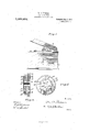
ingldrawing: igure l... a *talking machine :shouting-.my dev-ice afp'p K y isla Verticals 3 "is a" transier is anieiilfafrged plniiew et the ratchet'gears' fiori-Winding the talking lmachine on the upward vand" down-ward i provided a coiie f ch'i'ne is in operation," a
'andthe y reproducer f a inotor'aiid record] el'rig-- diuni shaft. machine,
when winding the moved or iiiiscrewed county zo over the freeord Whie pia-ying,- ingf1andiflowering of the cover@ Win `When-the cover is. 1.placed `thereon and 'tional vi ToaZZ whom #may concern Beit-known that foiti'fi'enV ot' the-United St fCleveland, 4in the i-State; of -v Ohio,
.invent-ion Vis to provide talking .machines ot er ltolet .down e. and the., raisds .the
that
'the drawings,
ing machine to inclo'se the record` and arin whenv the"iiiandivhereby the rec. jwliile Vjpia'yiiig and thus' gainst scratches caused'- Minuut` A. PossoNs, e ates, residing at t Cuyahoga ,and have invented 'certain new #und fuseul 'Improvements' in Talking-Maotlwhich vthe following isa specification, reifereiicef-beinghad therein .to theaoveoirnpaiiyio g Adiarfiiig.
My invention relatesto improvements `in o play the record. invention is 'to' prothis character attachedV to :any Welld' ettheI saine time lied thereto. 'Fig I2 ew of'jFig. '1. Fig. sesect-ionai -lview of" Figi Fig;'fiszanenlargediplan View ofthe. .gear-.'-
oiiiidz b t'hefcranlt rear. "A A. v'fthe o' 'that it xviii l' tighteiif* but can be reby turning it backward.
tending .segmental rack through the housing and operates atraiiiiq@ both. 'inoveineiit of the tions LG Which jtaiice'saround/'ti yareA eue seraiimueiee A l Y asy heretotore his, i lcoustruotedtobe appiie'd tottliefordinaryiiiachine and will noti-,have tovahandouwany `partj thereof, -norv no new. v.parts ujillfbcd. ref
quired except- .what .Eis absolutely necessary for-Windingthe ijnaehiiie,iff
Myt-improved' a casing 5, which is 4.rendi-lyseouredtofthe device, i
, inside ofthe hodyfi et,thetalkinginacliine.
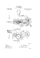
adjacent the druinfsha'ftv and crankshaft 3, in any desired maunei'.-The @ver2 `has rigidiy secured thereto 'thefdoivnivaijdlyfe'x- 6, Whioli eilt-ends of gear rtoirotating the shaft.t,which vwill he hereinafter more,ullyfdescivibedil *i The housing 5 is providedwavith.ii-,trous- 'vei-se longitudinal`shaft7,,upon which is mounted ai .gear 7Wheel i rectioii by the upward movement. ofthe-rack '6, and in the reverse diieet'ioii,v upon' the downward movement ing 5 on the inside of the gear Spie 1;) i'.ovided with a transverse-YhoiizoiitalpshiltaQQwhich isffre'e to rotate in .the It" ia.i'iie andlupouwhich is looselyA mounted a gear-10,- whielri at all ltiiiieeingear with the gearv-S,oyherehy'ithe direction .of rotation'.oflsaidpgearfist hyA the gear 8- as .hertufore described. -Looselyiuounted upon the yshait19,11onfeach side of the geanlis a gearl1l-alnd 12-,.The
center gear it) on eac-h sijdeiisiproyidedwith 'plates 18v and 14 heldupoii theqgeaieby rivets 15,- the two plates-'beingheideby the lf3 and 1.4 are provided'ivitliiftaperiiigfcut- ,-"a'Wa-y portions '16. xThefscut'- away portions .of one plate tapering yiii those of the other platertapeiz inthe opposite direction. ,The gears'll andv 12u11@ git-rim- !lilie torni havingvsecured totheinouterfftaces `:thfe' plates 17Hhfyg1iieansJueaiis of rivets I8:
fThef ctuitrall :openings e :ai ranged-:at equal; 'adiei ipheiyfof' thee. plates eler'o'llei 1Qv .heeerollrs'fwhen in the-'deep portion off'the taperingfcutaway portions" ailouf louv end, the gear is locked to the plate or to the central gear 10. These cutaway por- S., whichA at elle the ifre'ef'rotation ot .the'gear,
v jtiines: in mesh with the segineiitalrael; 6, A f and whereby the gear S isdi'iiren inloiie .d1-
1saine rivets?" The outerfedgegzof;ithefpiates `tions of one plate tapering in opposite direction to ythose of the other plate4 it will be seen that when the gearl10jis rotated in one direction the gear 11is locked thereto, and when rotated in the opposite direction, the gear 12 is locked thereto. The rollers 19 are held against inward movement by the gear 10 and againstoutward movement by the plates 17. f
The gear 12 is slightly larger in diameter than the gear 11, and meshes with an idle gear 21, mounted in the casing. The idle gear 21 meshes with lthe large gear 22, mounted upon the shaft 23 carried by the frame 5, and said gear 22 meshing with the gear 24 loosely mounted upon the shaft 4 of the spring drum. The gear 11 is smaller in diameter than the gear 12, and meshes directly with the gear 22. The gear M being loose upon the shaft 4, it will be seen that the said shaft can be rotated vby the crank 3, as heretofore described without operating the train of gearing.
In order tok lock the gear 24 to the shaft 4, or crank-3, I provide a sleeve 25, which' is slidable upon the shaft 4 or crank 3. Surrounding the sleeve is a plate 26, secured to the outer face of the vbody l, and surrounding the sleeve on the inside of the plate 26 is a coil spring 27, the outerend.-
of which bears against the 'plate and `the inner end secured to the sleeve and normally,
holding the sleeve in an inward posi'tm. The inner end of the sleeve is provided with notches 28, into which extend the lugs 29 carried by the gear 24, whereby the gear is locked to the sleeve. The sleeve is held upon the shaft 4 by means of a pin 30, working in a bayonet-slot 31 in the sleeve. When the pinisin the position shown in the drawings, the gear 24 is locked in the shaft 4 through the medium of the sleeve 25. Drawing the sleeve outwardly against the tension of the spring and turning it locks the sleeve in its outwardposition and uncouples the sleeve 25 from the gear 24.
In devices of this character, as heretofore stated, a cover protects t-he record while playing, and whenever a new record is yplaced on the machine the cover is raised and lowered. lVhn the cover is raised the rack 6 rotates the gear 8, and'this gear in turn rotates the central gear 10 in the reversedirection. The rotation of this gear 10 in this direction by means of the rollers.
8 in the opposite direction; this rotates vthe gear 10 in the opposite direction and ment of the rack.
By locking the sleeve25 in the outward position, as heretofore described, the gear 24 is disconnected from the shaft 4 and the shaft may be rotated by the crank 3, independent of the rack and its operating mechanism. lVhile I have shown and described this specific means ofv operating the springdrum Shaft, it will be -understood that the same can be vastly varied without departing from my invention.`
I claim- 1. The combination with a talking machine cabinet having a motor therein, of a recordv holding ymember and a reproducer carried by the cabinet, a cover closing the cabinet for inclosing theV record holding member and the reproducer, a winding-crank` carried by the motor, means operated by the movement of the cover for winding` the crank and means for disconnecting said winding `means from the crank.
2. The combination with a'talking machine cabinet having a motor therein, of a lrecord holding member and a reproducer `carried by the cabinet, a cover closing the cabinet for inclosing the record Iholding member and the reproducer, a winding crank for the motor,means operated by the cover for rotating the winding crank duringboth the upward and downward movement .ther'e of, and means for ,disconnectinof thepcover operating means from the cranzlr, whereby the' motor'may be wound by the crank.
3. The combinationl with a talking machine cabinet having a mptor therein,- of a record. holding member and a reproducer carried by the cabinet, a hinged cover closing the cabinet for inclosing the record holding member and the reproducer, a usual winding -shaft carried by the motor, a. gear loosely mounted upon the winding-shaft, .a
clutch mechanism carried by the shaft and`V held in engagement swith the gear by a spring, a bayonet slot connection between the clutch and-the shaft for holding the clutch' mechanism against rotation on the shaftv and locking itin its outward position out of engagement with the gear, a train of gearing meshing with the said loose gear, and aA rack carried bythe cover for operating the train of gearing.
4. Thecombination with a talking'machinev cabinet having a motor therein,of a i record holding memberA and a reproducer incense,
carried by the cabinet, a hinged cover closing the cabinet forinclosing therecord holding member and the reproducer, a crank for winding the moto-r, a loose gear carried by the crank, a clutch mechanism for locking the gear to the crank, a gear meshing with said loose gear, a train of gearing meshing with the last mentioned gear, and a segmental rack carried b the cover and adapted to operate said train of gearing, substantially as shown and described.
5. The combination with a talking machine cabinet having a motor therein, of a record holding member and a reproducer carried by the cabinet, a hinged cover closing the cabinet for inclosing the record holding member and the reproducer, a crank for Winding the'motor, a segmental rack carried by the cover and extending downwardly, a gear carried by the cabinet and meshing with said rack, a large gear meshing with the firstv mentioned gear, plates secured to both sides of said large gear and h aving tapering recesses in their outer edges, said recesses of one plate tapering in oppol site direction to that of the Othenplate, rollers in said recesses, a gear surrounding each plate and adapted to be locked thereto by the rotation of the large gear in differentdirections, and a train of gearing meshing with the outside gears and adapted to rotate the crank in the same direction by the upward and downward movement of the cover.
6. The combination with a talking machine cabinet having a motor therein', of a record holding member and a reproducer a movable portion operatively carried by the cabinet, a hinged cover ciosing the cabinet for inclosing the record heirling mem, i' the reproducen a winding crank 'cenni to the motor, a segmental rack carried by the cover, a gear carried. by the cabinet and meshing with lthe said segmental rack, an intermediate gear meshing with the first mentioned gear7 a gear on each side of the intermediate gear and of different diameters, .means for coupling the larger gear to the intermediate ear when revolving in one direction, an the smaller gear to the intermediate gear when revolving in the opposite direction, an idle gear meshing with the larger gear beside the intermediate gear, a gear meshing with the smaller gear beside theintermediate gear, and the idle gear, and a gear carried by the Winding crank'and meshing With the last mentioned gear, whereby the rack revolves the motor shaft in the same direction on the upward and downward movement` 7. In a talking machine, the combination with a motor and talking machine cabinet, of a motor Within the cabinet, two winding mechanisms for the motor, one operative in dependently of the other, the cabinet having l connected with one or the Winding mechanisms and a handle operatively connected to the other Winding mechanism.
In test'mony whereof I hereunto aiiiX my signature in the presence of two Witnesses.
MINARD ARTHUR POSSONS. Witnesses EDWARD A. SCHNEIDER, FRED. T. BATCHELOR.
Priority Applications (1)
| Application Number | Priority Date | Filing Date | Title |
|---|---|---|---|
| US52156609A US1069464A (en) | 1909-10-07 | 1909-10-07 | Talking-machine. |
Applications Claiming Priority (1)
| Application Number | Priority Date | Filing Date | Title |
|---|---|---|---|
| US52156609A US1069464A (en) | 1909-10-07 | 1909-10-07 | Talking-machine. |
Publications (1)
| Publication Number | Publication Date |
|---|---|
| US1069464A true US1069464A (en) | 1913-08-05 |
Family
ID=3137701
Family Applications (1)
| Application Number | Title | Priority Date | Filing Date |
|---|---|---|---|
| US52156609A Expired - Lifetime US1069464A (en) | 1909-10-07 | 1909-10-07 | Talking-machine. |
Country Status (1)
| Country | Link |
|---|---|
| US (1) | US1069464A (en) |
-
1909
- 1909-10-07 US US52156609A patent/US1069464A/en not_active Expired - Lifetime
Similar Documents
| Publication | Publication Date | Title |
|---|---|---|
| US1069464A (en) | Talking-machine. | |
| US1179924A (en) | Film-spool arbor. | |
| US1351938A (en) | Spring-winding mechanism for phonographs | |
| US1257180A (en) | Impulse-transmitter for automatic telephone systems. | |
| US1753505A (en) | Driving mechanism for turntables of talking machines | |
| US1473929A (en) | Winding indicator for talking machines | |
| US1257874A (en) | Camera attachment. | |
| US741215A (en) | Magazine photographic-plate holder. | |
| US1181306A (en) | Automobile-use-registering apparatus. | |
| US1275635A (en) | Attachment for phonographs. | |
| US994489A (en) | Combination player-piano and phonograph. | |
| US1234545A (en) | Film-handling device. | |
| US1454625A (en) | Gear train for phonograph motors | |
| US1473930A (en) | Winding indicator for talking machines | |
| US1146418A (en) | Phonograph. | |
| US743858A (en) | Phonographic attachment for music-boxes. | |
| US1494802A (en) | Rewinding device for phonograph motors | |
| US1573348A (en) | Talking machine | |
| US3499617A (en) | Cartridge for roll film | |
| USRE13224E (en) | Samuel c | |
| US1751903A (en) | Electrically-wound spring motor | |
| US842982A (en) | Talking-machine. | |
| US1656085A (en) | Jamxs s | |
| US1265473A (en) | Winding mechanism for spring-motors. | |
| US1146291A (en) | Camera. |