US10693767B2 - Method to route packets in a distributed direct interconnect network - Google Patents
Method to route packets in a distributed direct interconnect network Download PDFInfo
- Publication number
- US10693767B2 US10693767B2 US16/157,966 US201816157966A US10693767B2 US 10693767 B2 US10693767 B2 US 10693767B2 US 201816157966 A US201816157966 A US 201816157966A US 10693767 B2 US10693767 B2 US 10693767B2
- Authority
- US
- United States
- Prior art keywords
- node
- nodes
- interconnect network
- packets
- direct interconnect
- Prior art date
- Legal status (The legal status is an assumption and is not a legal conclusion. Google has not performed a legal analysis and makes no representation as to the accuracy of the status listed.)
- Active
Links
Images


Classifications
-
- H—ELECTRICITY
- H04—ELECTRIC COMMUNICATION TECHNIQUE
- H04L—TRANSMISSION OF DIGITAL INFORMATION, e.g. TELEGRAPHIC COMMUNICATION
- H04L45/00—Routing or path finding of packets in data switching networks
- H04L45/24—Multipath
-
- H—ELECTRICITY
- H04—ELECTRIC COMMUNICATION TECHNIQUE
- H04L—TRANSMISSION OF DIGITAL INFORMATION, e.g. TELEGRAPHIC COMMUNICATION
- H04L45/00—Routing or path finding of packets in data switching networks
- H04L45/12—Shortest path evaluation
-
- H—ELECTRICITY
- H04—ELECTRIC COMMUNICATION TECHNIQUE
- H04L—TRANSMISSION OF DIGITAL INFORMATION, e.g. TELEGRAPHIC COMMUNICATION
- H04L45/00—Routing or path finding of packets in data switching networks
- H04L45/26—Route discovery packet
-
- H—ELECTRICITY
- H04—ELECTRIC COMMUNICATION TECHNIQUE
- H04L—TRANSMISSION OF DIGITAL INFORMATION, e.g. TELEGRAPHIC COMMUNICATION
- H04L45/00—Routing or path finding of packets in data switching networks
- H04L45/40—Wormhole routing
-
- H—ELECTRICITY
- H04—ELECTRIC COMMUNICATION TECHNIQUE
- H04L—TRANSMISSION OF DIGITAL INFORMATION, e.g. TELEGRAPHIC COMMUNICATION
- H04L47/00—Traffic control in data switching networks
- H04L47/50—Queue scheduling
- H04L47/62—Queue scheduling characterised by scheduling criteria
- H04L47/622—Queue service order
- H04L47/6225—Fixed service order, e.g. Round Robin
-
- H—ELECTRICITY
- H04—ELECTRIC COMMUNICATION TECHNIQUE
- H04L—TRANSMISSION OF DIGITAL INFORMATION, e.g. TELEGRAPHIC COMMUNICATION
- H04L45/00—Routing or path finding of packets in data switching networks
- H04L45/34—Source routing
Definitions
- the present invention relates to a computer network for data center and cloud data center servers interconnect.
- the present invention relates to a method for routing packets in a direct interconnect network implemented on a torus or higher radix topologies such as the “dragonfly” wiring structure.
- DC Data Centers
- CDC Cloud Data Centers
- Network switches are computer networking apparatus that link network devices for communication/processing purposes.
- a switch is a telecommunication device that is capable of receiving a message from any device connected to it, and transmitting the message to a specific device for which the message is to be relayed.
- a network switch is also commonly referred to as a multi-port network bridge that processes and routes data.
- port we are referring to an interface (outlet for a cable or plug) between the switch and the computer/server/CPU to which it is attached.
- Layer two switches process and route data at layer 2, the data link layer, which is the protocol layer that transfers data between nodes (e.g. servers) on the same local area network or adjacent nodes in a wide area network.
- a key problem to solve, however, is how to build a large capacity computer network that is able to carry a very large aggregate bandwidth (hundreds of TB) containing a very large number of ports (thousands), that requires minimal structure and space (i.e. minimizing the need for a large room to house numerous cabinets with racks of cards), and that is easily scalable, and that may assist in minimizing power consumption.
- the traditional network topology implementation is based on totally independent switches organized in a hierarchical tree structure as shown in FIG. 1 .
- Core switches 2 are very high speed, low count ports with a very large switching capacity.
- the second layer is implemented using aggregation switches 4 , medium capacity switches with a larger number of ports, while the third layer is implemented using lower speed, large port count (e.g. forty/forty-eight), low capacity Edge switches 6 .
- the edge switches are layer 2
- the aggregation ports are layer 2 and/or 3
- the core switch is typically layer 3.
- This implementation provides any server 8 to any server connectivity in a maximum of six hop links in the example provided (three hops up to the core switch 2 and three down to the destination server 8 ).
- Such a hierarchical structure is also usually duplicated for redundancy-reliability purposes. For example, with reference to FIG. 1 , without duplication if the right-most edge switch 6 fails, then there is no connectivity to the right-most servers 8 . In the least, core switch 2 is duplicated since the failure of the core switch 2 would generate a total data center connectivity failure. For reasons that are apparent, this method has significant limitations in addressing the challenges of the future CDC. For instance, because each switch is completely self-contained, this adds complexity, significant floor-space utilization, complex cabling and manual switches configuration/provisioning that is prone to human error, and increased energy costs.
- a torus interconnect system is a network topology for connecting network nodes (servers) in a mesh-like manner in parallel computer systems.
- a torus topology can have nodes arranged in 2, 3, or more (N) dimensions that can be visualized as an array wherein processors/servers are connected to their nearest neighbor processors/servers, and wherein processors/servers on opposite edges of the array are connected.
- N network nodes
- FIG. 2 provides an example of a 3-D torus interconnect.
- a torus topology provides access to any node (server) with a minimum number of hops.
- a four dimension torus implementing a 3 ⁇ 3 ⁇ 3 ⁇ 4 structure (108 nodes) requires on average 2.5 hops in order to provide any to any connectivity.
- FIG. 4 provides an example of a 6 ⁇ 6 2-D torus, showing the minimum number of hops required to go from corner node 1.6 to all other 35 nodes.
- the number of hops required to reach any destination from node 1.6 can be plotted as a bell-curve with the peak at 3 hops (10 nodes) and tails generally at 5 hops (4 nodes) and 1 hop (4 nodes), respectively.
- large torus network implementations have not been practical for commercial deployment in DCs or CDCs because large implementations can take months to build, cabling can be complex (2N connections for each node), and they can be costly and cumbersome to modify if expansion is necessary.
- the implementation of torus topologies in supercomputers has been very successful.
- IBM's Blue Gene supercomputer provides an example of a 3-D torus interconnect network wherein 64 cabinets house 65,536 nodes (131,072 CPUs) to provide petaflops processing power (see FIG. 3 for an illustration), while Fujitsu's PRIMEHPC FX10 supercomputer system is an example of a 6-D torus interconnect housed in 1,024 racks comprising 98,304 nodes. While the above examples dealt with a torus topology, they are equally applicable to other flat network topologies.
- the present invention deals more specifically with the important issue of data packet traverse and routing from node to node in torus or higher radix network structures.
- it is the routing that determines the actual path that packets of data take to go from source to destination in the network.
- latency refers to the time it takes for a packet to reach the destination in the network, and is generally measured from when the head arrives at the input of the source node to when it arrives at the input of the destination node.
- Hop count refers to the number of links or nodes traversed between the source and the destination, and represents an approximation for determining latency.
- Throughput is the data rate that the network accepts per input port/node measured in bits/sec.
- a useful goal when routing is to distribute the traffic evenly among the nodes (load balancing) so as to avoid hotspots development (a pathway or node region where usage/demand has exceeded a desired or acceptable threshold) and to minimize contention (when two or more nodes attempt to transmit a message or packet across the same wire or path at the same time), thereby improving network latency and throughput.
- the route chosen therefore affects the number of hops from node to node, and may potentially even thereby affect energy consumption when the route is not optimized.
- topology under which a network operates also clearly affects latency because topology impacts the average minimum hop count and the distance between nodes. For instance, in a torus, not only are there several paths that a packet can take to reach a destination (i.e. in a torus there is “path diversity”), but there are also multiple minimum length paths between any source and destination pair. As an example, FIG. 5 shows examples of three minimal routes that a packet can take to go from node S 11 to node D 12 (3 hops) in a 2-D torus mesh, while a longer fourth route of 5 hops is also shown. The paths computation done through routing is done statically based on topology only—the source routing is dynamically based on packet source-destination pairs on hop by hop basis.
- Routing methodologies that exploit path diversity have better fault tolerance and better load balancing in the network. Routing methodologies do not always achieve such goals, however, and can generally be divided into three classes: deterministic, oblivious and adaptive.
- Deterministic routing refers to the fact that the route(s) between a given pair of nodes is determined in advance without regard to the current state of the network (i.e. without regard to network traffic).
- Dimension Order Routing is an example of deterministic routing, wherein all messages from node A to node B will always traverse the same path. Specifically a message traverses dimension-by-dimension (X-Y routing), thereby reaching the ordinate matching its destination in one dimension before switching to the next dimension. As an example, FIG.
- Routing algorithms that are “oblivious” are those wherein routing decision are made randomly without regard to the current state of the network (deterministic routing is a subset of oblivious routing). Although this means oblivious routing can be simple to implement, it is also unable to adapt to traffic and network circumstances.
- An example of a well-known oblivious routing method is the Valiant algorithm (known to persons skilled in the art). In this method, a packet sent from node A to node B is first sent from A to a randomly chosen intermediate node X (one hop away), and then from X to B.
- Valiant algorithm could randomly chose node 2 as an intermediate node from source node 1 to destination node 10, meaning the path 1-2-3-7-11-10, for instance, could be used for routing purposes. This generally randomizes any traffic pattern, and because all patterns appear to be uniformly random, the network load is fairly balanced. In fact, the Valiant algorithm has been thought to be able to generally balance load for any traffic patterns on almost any topology.
- Valiant routes are generally non minimal (minimal routes are paths that require the smallest number of hops between source and destination), which often results in a significant hop count increase, and which further increases network latency and may potentially increase energy consumption. There are exceptions, however, such as in a network where congestion is minimal.
- Non-minimal routing can significantly increase latency and perhaps power consumption as additional nodes are traversed; on the other hand, in a network experiencing congestion, non-minimal routing may actually assist in avoiding nodes or hotspots, and thereby actually result in lower latency.
- the Valiant algorithm can be modified to restrict its random decisions to minimal routes/shortest paths by specifying that the intermediate mode must lie within a minimal quadrant.
- the minimal quadrant for node 1 (having a destination of node 10) would encompass nodes 2, 5, and 0, and would lead to a usual hop count of 3.
- the Valiant algorithm provides some level of path selection randomization that will reduce the probability of hot spots development. There is a further conundrum, however, with affecting such efficiencies—Valiant routing is only deadlock free when used in conjunction with DOR routing, which itself fails with load balancing and hot spots avoidance.
- Adaptive routing algorithms are those wherein routing decisions are based on the state of the network or network traffic. They generally involve flow control mechanisms, and in this respect buffer occupancies are often used. Adaptive routing can employ global node information (which is costly performance-wise), or can use information from just local nodes, including, for instance, queue occupancy to gauge network congestion. The problem with using information solely from local nodes is that this can sometimes lead to suboptimal choices. Adaptive routing can also be restricted to minimal paths, or it can be fully adaptive (i.e. no restrictions on taking the shortest path) by employing non-minimal paths with the potential for livelock (i.e. a situation similar to deadlock where the packet travel is not progressing to destination; often the result of resource starvation).
- Another problem with adaptive routing is that it may cause problems with preserving data packet ordering—the packets need to arrive at the destination in the same order or otherwise you need to implement packet reordering mechanisms.
- routing can be implemented by source tables or local tables.
- source tables the entire route is specified at the source, and can be embedded into the packet header. Latency is thereby minimized since the route does not need to be locked up or routed hop by hop at each node.
- Source tables can also be made to specify multiple routes per destination to be able to manage faults, and, when routes are selected randomly (i.e. oblivious routing), to increase load balancing.
- routes are selected randomly (i.e. oblivious routing), to increase load balancing.
- local node tables on the other hand, smaller routing tables are employed. However, the next step a packet is to take is determined at each node, and this adds to per hope latency.
- the present invention seeks to overcome deficiencies in the prior art and improve upon known methods of routing packets in torus or higher radix network topologies.
- the present invention provides a novel method to route data packets across a torus mesh or higher radix topologies to provide low latency, increased throughput, and hot spot and deadlock avoidance.
- the present invention provides a method to implement traffic decorelation (randomization), increased efficiency in bandwidth allocation, load balancing and traffic engineering in a torus mesh or higher radix structures.
- the present invention provides a computer-implemented method of routing packets in a direct interconnect network from a source node to a destination node comprising the steps of: discovering all nodes and all output ports on each node in a network topology; including the discovered nodes and output ports in the network topology in a topology database in order to allow said nodes and ports to be included in shortest path routing computations; calculating the shortest path from every output port on each node to every other node in the network topology based on those nodes and output ports contained in the topology database; generating a source routing database on each node containing the shortest paths from every output port on said each node to all other nodes in the network topology; receiving packets at the source node; sending the received packets to the output ports of the source node in a round robin or weighted round robin manner, whereby each of said received packets is thereafter segmented into flits at the output port of the source node and distributed along the shortest path from
- the present invention provides a method of routing packets wherein the flits are forwarded to the destination node using wormhole switching.
- FIG. 1 is a high level view of the traditional data center network implementation
- FIG. 2 is diagram of a 3-dimensional torus interconnect having 8 nodes
- FIG. 3 is a diagram showing the hierarchy of the IBM Blue Gene processing units employing torus architecture
- FIG. 4 is a high level diagram of the 36 nodes in a 6 ⁇ 6 2-D folded torus that displays the minimum number of hops required to reach any of the 35 nodes starting from corner node (1.6);
- FIG. 5 is a diagram of a 4 ⁇ 4 2-D torus implementation displaying several routes starting from node S to node D on every port (x+, x ⁇ , y+, y ⁇ ) of node S;
- FIG. 6 is a diagram of a simple network topology to assist in showing how various routing algorithms could route a packet from node to node;
- FIG. 7 is a high level diagram of a high speed Network Interface Card with all the ports in accordance with the system of present invention.
- FIG. 8 is a high level diagram of a Host Network Interface (HNI) card showing the key functional blocks in accordance with the system of the present invention
- FIG. 9 is a high level view of packet segmentation required to implement packet transfer across a torus mesh
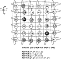
- FIG. 10 is a diagram showing the routes and the number of hops starting from each port on node S (2.4) to each port on node D (5.2) in a 36 node 2-D torus structure;
- FIG. 11 shows a high level diagram presenting the software components: TD, SR, WS, FC in accordance with the present invention
- FIG. 12 shows a flowchart for the process of packet segmentation in accordance with the present invention
- FIG. 13 displays the pseudocode implementing the flit generation through packet segmentation
- FIG. 14 displays a flowchart of the processing steps to prepare the source routing from each port in accordance with the present invention
- FIG. 15 displays the pseudocode implementing the paths computation in accordance with the present invention.
- FIG. 16 displays the source routing tables format generated by the paths computation in accordance with the present invention
- FIG. 17 displays a flowchart for the process of transferring the “flits” on each port in accordance with the present invention
- FIG. 18 displays the wormhole switching process of transferring the “flits” on each port in accordance with the present invention
- FIG. 19 displays the pseudocode implementing the flits transfer as described in the flowchart in FIG. 17 , in accordance with the present invention.
- FIG. 20 displays a flowchart for discovering nodes or links triggering the topology discovery process for topology update
- FIG. 21 displays a flowchart for describing the topology data base update
- FIG. 22 shows a flowchart for the process of node and/or link failure detection and recovery and the process of topology update.
- FIG. 23 displays the pseudocode implementing the link and/or node failure detection in accordance with the present invention.
- the present invention utilizes a torus mesh or higher radix wiring to implement direct interconnect switching for data center applications.
- the present invention is particularly useful with the torus system described in related PCT Patent application no. PCT/CA2014/000652 entitled, “Method and Apparatus to Manage the Direct Interconnect Switch Wiring and Growth in Computer Networks”, filed Aug. 29, 2014, the disclosure of which is incorporated herein by reference.
- Such architecture can provide a high performance network interconnect having tens of thousands of servers in a single switching domain.
- the software that controls the switch follows the Software Defined Networks model.
- the switch control plane (Switch OS) preferably runs on a separate server but interacts closely with the distributed processing running on each PCIe card.
- key software components include the Topology Discovery (TD), the packet Routing (SR) across the topology, the wormhole switching (WS), the Flow Control (FC) mechanism, and the Switch Status Monitoring and Switch management.
- the TD component is responsible for essentially discovering the presence (or absence) of nodes in the torus mesh (and thereby allowing for the updating of possible paths based on node presence); the SR component is responsible for source routing calculations (all the paths available from every port of the source node to any destination node); the WS component is responsible for flit steering across the torus based on the path vector, which is included in the flit header, with minimum latency (cut through model at every node); the FC component is responsible for torus links utilization and control messages to the source in order to regulate the traffic through the input queuing mechanism; the switch status monitoring component is responsible for traffic balancing, traffic reroute in failure conditions and support for switch growth; and the switch management component is responsible for maintaining a complete image of the switch, including all the interconnected servers, all the interconnected I/O links to the outside world, and connectivity status.
- the present invention primarily relates to the novel topology discovery (TD component) and routing protocol (SR component) of the present invention—key functions particularly useful for implementation on the novel switch architecture disclosed in PCT Patent application no. PCT/CA2014/000652. While traditional implementations of routing data packets through a torus structure makes an implicit assumption, namely that the traffic is randomly distributed across the destination nodes, practical implementations have actually shown switch failures in the case of single source/single destination continuous packet flow at maximum capacity, due to hotspots development that propagates across the torus, and which has the capacity to completely disable the ability to transfer packets across the torus mesh.
- TD component topology discovery
- SR component routing protocol
- the present invention is therefore referring more specifically to routing optimisation and implementation for direct interconnect network topologies such as torus and higher radix networks in order to address performance issues and hot spots development for any type of traffic (whether large flows from any source to any destination (highly correlated) or traffic to randomly distributed destinations (typical internet traffic)).
- the present invention describes a method of discovering and updating all nodes in the topology, and a method of routing packets wherein the shortest path(s) are calculated at each node on every output port (e.g. x+, x ⁇ , y+, y ⁇ , z+, z ⁇ , w+, and w ⁇ ) to every destination node, and whereby the packets are distributed along paths from each output port in a round-robin manner or weighted round-robin manner (i.e. promoting multiple alternate paths) to increase bandwidth and traffic distribution to avoid hotspots.
- every output port e.g. x+, x ⁇ , y+, y ⁇ , z+, z ⁇ , w+, and w ⁇
- FC flow control
- Data packet reordering is implemented at the node destination.
- Such a method can take particular advantage of the novel method of node (server) discovery discussed in PCT Patent application no. PCT/CA2014/000652, and further discussed herein.
- the present invention therefore addresses the issue of packet routing optimization for direct interconnect network topologies such as torus or higher radix networks, in order to address performance issues and hotspots development for any type of traffic, whether that be large flows from any source to any destination (highly correlated) or traffic to randomly distributed destinations (typical internet traffic).
- FIG. 7 displays a high level diagram of the high speed Network Interface card 10 with all the ports: the I/O port 13 to access the outside world (N-S interface), the 4D torus interconnect ports 14 , the PCIe port 15 to access the compute server and the control 19 .
- N-S interface the outside world
- 4D torus interconnect ports 14 the 4D torus interconnect ports 14
- PCIe port 15 to access the compute server and the control 19 .
- FIG. 7 displays a high level diagram of the high speed Network Interface card 10 with all the ports: the I/O port 13 to access the outside world (N-S interface), the 4D torus interconnect ports 14 , the PCIe port 15 to access the compute server and the control 19 .
- the present invention could work with HNI cards having fewer or more ports, and in association with other torus or higher radix topologies (such as “dragonfly” for example).
- FIG. 8 shows a high level diagram for the HNI card 10 in accordance with the system of the present invention with the key functional blocks, including the processor 31 with RAM 37 and ROM 38 , the switching block 32 , the physical interface devices 36 , the torus interconnect ports 14 , the I/O port 13 and the PCIe port 15 .
- the physical implementation of this embodiment is based on a multicore processor with attached memories and PHY devices to implement the torus interconnect.
- the switching function is implemented in software using the processor's hardware acceleration assist capability to support multiple queues manipulation.
- the present invention would also work if the physical implementation differs. i.e if the switching function acceleration is implemented in FPGA or ASIC, or, that the processor does not have to reside on the same card as the card used for the switching function.
- FIG. 10 displays a simple 2D torus wiring diagram for use in explaining packet routing in accordance with the present invention.
- the structure is a folded 2D torus wherein the length of each connection is equivalent throughout.
- Each node in this diagram represents a server interconnected via a PCIe switch card (described above) that is housed in the server.
- the diagram shows the shortest maximum disjoint paths (no links or nodes in common) from the ports of source node S (2.4) to destination node D (5.2) starting on the various dimensions (x+, x ⁇ , y+, y ⁇ ), as calculated at the source node S.
- FIG. 10 displays a simple 2D torus wiring diagram for use in explaining packet routing in accordance with the present invention.
- the structure is a folded 2D torus wherein the length of each connection is equivalent throughout.
- Each node in this diagram represents a server interconnected via a PCIe switch card (described above) that is housed in the server.
- the diagram shows the shortest maximum
- 10 shows three calculated paths and the routing vectors as having a minimal hop count of 5 hops (from (S) 2.4: (x+, x+, x+, y ⁇ , y ⁇ ); from (S) 2.4: (y ⁇ , y ⁇ , x+, x+, x+); and from (S) 2.4: (x ⁇ , x ⁇ , y ⁇ , y ⁇ , x ⁇ ), while another path is calculated as having a non-minimal hop count of 7 hops (from (S) 2.4: (y+, y+, y+, x+, x+, x+, y+)).
- the packets/flits will be sent on the shortest path to node D starting on each source node S output port to the destination node along the path from each output port in a round-robin or weighted round-robin manner, thereby using multiple paths to increase the bandwidth on one hand and distributing the traffic to avoid hot spots development (weighted round-robin selection of output ports at the source node would increase the number of packets along certain paths).
- a second alternate route may also computed and stored at each node, whereby, other than the first hop, the routes provide alternate, separate paths to assist in the case of link or node failures to overcome traffic congestion, and hotspots as necessary.
- the present method distributes the traffic across the torus or higher radix network for load balancing purposes, but can introduce packet reordering. For instance, since the path starting on y+( FIG. 10 ) is 2 hops longer than the minimal paths (5 hops), all the packets sent on this path will arrive with an extra delay that can generate packet reordering issues. Packets therefore have to be re-ordered at the destination node in accordance with the present invention. This is within the skill of a person skilled in the art.
- FIG. 9 which shows a high level view of packet segmentation
- packets traversing the direct interconnect tori or higher radix are segmented into smaller sized packets (flits) during routing.
- Packet segmentation is required across the torus mesh in order to avoid “Head of Line Blocking”, a common condition in packet networks using common resources (links and buffers).
- the size of the flit is determined by the traffic type in order to minimize overhead tax, and the practical value ranges between 64 and 512 bytes. It is important to note that the present invention is able to handle Ethernet packets, Infiniband packets, PCIe streams or NVMe transactions, among possible others.
- the flits across the torus structure are transparently carrying the traffic.
- the external interface I/O port 13 is specific to the type of traffic and terminates the user traffic, transferring the data across the torus to a destination PCIe port 15 transparently via “flits”. It is important to note that the present invention is able to handle Ethernet packets across the torus (via Ethernet flits).
- a key advantage herein is the variable size of the flit, since the flit for an Ethernet packet has the packet delineation mechanism. Therefore, the flit size is variable from 64 bytes (the minimum Ethernet packet size) to 512 bytes (payload and headers). If the packet is larger than 512 bytes the system will segment the original packet into flits of 512 bytes: the Head flit, the Body flit, and the Tail flit.
- FIG. 12 provides a flowchart presenting the method of packet segmentation.
- the HNI processor extracts the header in order for the processor to analyse the packet's destination (step 404 ) and the routing paths.
- the packet enters the segmentation loop.
- the bytes counter is initialized (step 412 ) and End of Packet—EOP-analyser (step 405 ) detects the EOP, and if the counter is less than or equal to 476 bytes (i.e.
- the packet is sent to flit generator (step 407 ), the header generator (step 408 ) and priority decision block (step 409 ).
- the flit is thereafter inserted into an assigned exit queue (step 410 ) for transmission to the next hop across the torus mesh, and we look to see if a new packet has been received ( 402 ).
- the byte counter is incremented (step 411 ) after each individual flit, the packet fragment is sent to the flit generator (step 407 ) and the process follows the steps described above until the last flit in the packet is reached and transmitted.
- the flits on the torus links are preferably 512 bytes (476 bytes payload and 36 bytes header) followed by 8 “idle” bytes. If the packet is shorter than 476 bytes the flit (usually the Tail flit) will have less than 512 bytes and the packet delineation will be done using the “idle” bytes.
- FIG. 13 provides pseudocode implementing flit generation through packet segmentation.
- FIG. 14 shows the flowchart presenting the route computation according to the invention.
- the present invention also provides the pseudo code at FIG. 15 to compute all the paths from the source node to any destination node (source routing) that are maximally disjoint (no links and nodes in common) on each output port of the source node.
- the topology update function 412 (which discovers active servers/nodes and active ports thereof) will initiate route/path computation ( 414 ) as soon as an update is detected (i.e. whenever nodes have been added/deleted or there are critical problems/faults associated therewith).
- the shortest path will be computed (step 415 ) using Dijkstra algorithm, between the current node and each destination node from the topology, as described in steps 419 (first Destination node found in the topology list) followed by steps 420 and 421 (search for all destination nodes in the topology list).
- all path costs affected by step 417 are reset to the initial value.
- the computed shortest path from source to destination will be stored in the source routing data base and it will be removed from further shortest path computations (in order to provide for disjoint paths) by increasing the cost on all links belonging to the stored path to infinity ( 417 )—this will have the practical effect of removing the nodes and the links from the topology data base to force non-reuse for disjoint path selection purposes.
- the process continues until all the output ports will be used and all possible paths between the source node and the destination node are stored in the data base.
- the results are then summarized in the output routing table ( 418 ) as the routing vector for each node, where routing is to begin with shortest path first.
- Shortest path computation itself can be implemented using the Dijkstra algorithm, a well-known method used in routing protocol implementations. What is particularly novel herein is that the shortest path is determined at every output port and used accordingly.
- FIG. 16 presents the format of the routing output table. Each route has a number attached representing the number of hops for the specific path and the list/vector of the output ports to be selected on each hop.
- FIG. 16 presents an example snapshot of the output table for the routes in a 4-D torus (8 ⁇ 8 ⁇ 8 ⁇ 8) with 8 ports (x+, x ⁇ , y+, y ⁇ , z+, z ⁇ , w+ and w ⁇ ), from the source node number 1000 to the destination node 0 (the use of node 1000 and node 0 are simply for example purposes).
- the first output selection in the grouping of 8 routes i.e.
- the first group of 8 routes in the first group of 8 routes, for instance, corresponds to each output port of the source node.
- the 8 paths are totally disjoint and with different lengths: 5 hops, 7 hops or 9 hops.
- the feature that is most important is the paths distribution across the torus which enables traffic distribution and predictable performance.
- the second group of 8 paths in FIG. 16 represents the second alternative for the routing paths. The method may compute many alternate routes but the distance (number of hops) will get larger and larger. For practical reasons the method may generally only store the first option of 8 distinct paths if desired.
- FIG. 17 shows a flowchart representing the steps used in packet switching in accordance with the present invention.
- the packet transfer state machine initiates the transfer across the torus.
- the output port “k” in question (ports 1 to 8 i.e. the output port discussed above: x+, y+, z+, w+, x ⁇ , y ⁇ , z ⁇ and w ⁇ ) is used to transfer the flits following a wormhole model (as shown in FIG. 18 ): the Head flit and subsequent flit increments (Body flits), will be transferred along the same path from port k until the end of packet (the Tail flit) is reached as shown in FIG. 17 .
- the counter k increments to refer to the next output port and the next packet with the next packet identifier (designated the next ordered packet) is transferred on the torus on a flit by flit basis using this wormhole switching model.
- This implementation will distribute the packets sourced by one node on all the output ports 14 of the node, in a round robin model in order to decorelate the long flows to specific destinations and avoid “hot spots” development in the torus mesh.
- FIG. 19 displays the pseudocode implementing the flits transfer as described and shown in the flowchart at FIG. 17 .
- FIG. 20 shows a flowchart presenting a method of topology discovery in accordance with the present invention.
- the Topology Discovery component is important for essentially discovering the presence (or absence) of nodes (and node ports) in the torus mesh, which nodes/ports may then be used in the routing distribution above.
- the TD allows the novel network of the present invention, as particularly disclosed in PCT patent application no. PCT/CA2014/000652, to scale in a simplified and efficient manner.
- the TD is based on “Hello” protocol and database exchange protocol. In particular, the “Hello” message is sent and received on every node and every port.
- the local node information is updated to indicate availability of the new link to the neighbor.
- the collection of the node information is maintained on each node in the neighbor data base and synchronized with the neighbors through the Data Base exchange protocol.
- Each node sends its changes to the neighbor Data Base to the neighbor nodes, propagating step by step the entire topology.
- a function call is generated for paths computation. For the “Hello” message exchange, neighbor to neighbor continues forever at a defined time interval, in order to detect changes in topology.
- FIG. 21 shows the flowchart presenting the DB exchange update for topology discovery according to the invention.
- FIG. 22 provides a flowchart presenting how the system of the present invention discovers node/link failure detection and the process of re-routing to avoid the failed node.
- the pass-through block is programmed so that traffic destined for the failed link is rerouted to CPU 603
- the traffic source is notified to send traffic avoiding the failed link 604 . This triggers a topology update event 605
- FIG. 23 provides the pseudocode for the link/node failure detection and recovery.
- One embodiment of the invention is the method for new node insertion.
- the wiring interconnecting the existing nodes is interrupted (link cut).
- the traffic reroute API is invoked 604 .
- the link cost is set to infinity and the topology is updated (computing the shortest (lower cost) path for all the switch nodes). This defines the routes that will be used to control the packet flows to reach any destination.
- the new node insertion triggers the neighbors discovery.
- the management software checks the new node ID and compares with the provisioned data base. If the node is valid, the software initiates the process of topology update and the routes computation.
- the management data base will be updated with the new node and the node status will be set as active.
Landscapes
- Engineering & Computer Science (AREA)
- Computer Networks & Wireless Communication (AREA)
- Signal Processing (AREA)
- Data Exchanges In Wide-Area Networks (AREA)
Abstract
Description
Claims (11)
Priority Applications (2)
| Application Number | Priority Date | Filing Date | Title |
|---|---|---|---|
| US16/157,966 US10693767B2 (en) | 2014-02-13 | 2018-10-11 | Method to route packets in a distributed direct interconnect network |
| US16/908,669 US11362934B2 (en) | 2014-02-13 | 2020-06-22 | Method to route packets in a distributed direct interconnect network |
Applications Claiming Priority (4)
| Application Number | Priority Date | Filing Date | Title |
|---|---|---|---|
| US201461939487P | 2014-02-13 | 2014-02-13 | |
| PCT/CA2015/000081 WO2015120539A1 (en) | 2014-02-13 | 2015-02-13 | Method to route packets in a distributed direct interconnect network |
| US201615114722A | 2016-07-27 | 2016-07-27 | |
| US16/157,966 US10693767B2 (en) | 2014-02-13 | 2018-10-11 | Method to route packets in a distributed direct interconnect network |
Related Parent Applications (2)
| Application Number | Title | Priority Date | Filing Date |
|---|---|---|---|
| US15/114,722 Continuation US10142219B2 (en) | 2014-02-13 | 2015-02-13 | Method to route packets in a distributed direct interconnect network |
| PCT/CA2015/000081 Continuation WO2015120539A1 (en) | 2014-02-13 | 2015-02-13 | Method to route packets in a distributed direct interconnect network |
Related Child Applications (1)
| Application Number | Title | Priority Date | Filing Date |
|---|---|---|---|
| US16/908,669 Continuation US11362934B2 (en) | 2014-02-13 | 2020-06-22 | Method to route packets in a distributed direct interconnect network |
Publications (2)
| Publication Number | Publication Date |
|---|---|
| US20190068484A1 US20190068484A1 (en) | 2019-02-28 |
| US10693767B2 true US10693767B2 (en) | 2020-06-23 |
Family
ID=53799463
Family Applications (3)
| Application Number | Title | Priority Date | Filing Date |
|---|---|---|---|
| US15/114,722 Active 2035-06-08 US10142219B2 (en) | 2014-02-13 | 2015-02-13 | Method to route packets in a distributed direct interconnect network |
| US16/157,966 Active US10693767B2 (en) | 2014-02-13 | 2018-10-11 | Method to route packets in a distributed direct interconnect network |
| US16/908,669 Active US11362934B2 (en) | 2014-02-13 | 2020-06-22 | Method to route packets in a distributed direct interconnect network |
Family Applications Before (1)
| Application Number | Title | Priority Date | Filing Date |
|---|---|---|---|
| US15/114,722 Active 2035-06-08 US10142219B2 (en) | 2014-02-13 | 2015-02-13 | Method to route packets in a distributed direct interconnect network |
Family Applications After (1)
| Application Number | Title | Priority Date | Filing Date |
|---|---|---|---|
| US16/908,669 Active US11362934B2 (en) | 2014-02-13 | 2020-06-22 | Method to route packets in a distributed direct interconnect network |
Country Status (12)
| Country | Link |
|---|---|
| US (3) | US10142219B2 (en) |
| EP (1) | EP3087708B1 (en) |
| JP (1) | JP6267367B2 (en) |
| KR (1) | KR101809396B1 (en) |
| CN (2) | CN110708241B (en) |
| AU (1) | AU2015218201B2 (en) |
| BR (1) | BR112016018294A2 (en) |
| CA (1) | CA2939402C (en) |
| DK (1) | DK3087708T3 (en) |
| IL (1) | IL246982B (en) |
| NO (1) | NO2776466T3 (en) |
| WO (1) | WO2015120539A1 (en) |
Cited By (3)
| Publication number | Priority date | Publication date | Assignee | Title |
|---|---|---|---|---|
| RU2753147C1 (en) * | 2020-11-20 | 2021-08-12 | Федеральное государственное бюджетное учреждение науки Институт проблем управления им. В.А. Трапезникова Российской академии наук | Method for organizing optimal fault-tolerant multidimensional tori based on low-port routers and duplex channel splitters |
| WO2023012518A1 (en) * | 2021-08-05 | 2023-02-09 | Rockport Networks Inc. | Method for signaling link or node failure in a direct interconnect network |
| US20230066045A1 (en) * | 2021-08-30 | 2023-03-02 | Taiwan Semiconductor Manufacturing Co., Ltd. | Diagonal torus network |
Families Citing this family (43)
| Publication number | Priority date | Publication date | Assignee | Title |
|---|---|---|---|---|
| NO2776466T3 (en) | 2014-02-13 | 2018-01-20 | ||
| US10469368B2 (en) * | 2015-03-28 | 2019-11-05 | Intel Corporation | Distributed routing table system with improved support for multiple network topologies |
| US10084860B2 (en) * | 2015-04-09 | 2018-09-25 | Electronics And Telecommunications Research Institute | Distributed file system using torus network and method for configuring and operating distributed file system using torus network |
| US20170171084A1 (en) * | 2015-12-09 | 2017-06-15 | Alcatel-Lucent Usa, Inc. | Valiant load balanced segment routing |
| JP2017120542A (en) * | 2015-12-28 | 2017-07-06 | 富士通株式会社 | Parallel information processor, data transmission method, and data transmission program |
| US10572537B2 (en) * | 2016-04-13 | 2020-02-25 | International Business Machines Corporation | Efficient graph optimization |
| US9954611B1 (en) * | 2016-12-16 | 2018-04-24 | Futurewei Technologies, Inc. | System and method for abstracting wavelength-switched optical network traffic engineering topology in SDN control hierarchy |
| KR102610984B1 (en) * | 2017-01-26 | 2023-12-08 | 한국전자통신연구원 | Distributed file system using torus network and method for operating of the distributed file system using torus network |
| CN109218176B (en) * | 2017-06-30 | 2020-12-15 | 华为技术有限公司 | Method and device for processing message |
| US11347774B2 (en) * | 2017-08-01 | 2022-05-31 | Salesforce.Com, Inc. | High availability database through distributed store |
| CN107733802B (en) * | 2017-09-18 | 2020-11-13 | 深圳市盛路物联通讯技术有限公司 | Node control method and system of distributed network topology structure |
| CA2982147A1 (en) * | 2017-10-12 | 2019-04-12 | Rockport Networks Inc. | Direct interconnect gateway |
| US10855581B2 (en) | 2017-11-10 | 2020-12-01 | Fabriscale Technologies AS | System and method of computing ethernet routing paths |
| CN110166310B (en) * | 2018-01-30 | 2020-08-21 | 山东衡昊信息技术有限公司 | A Fast Calculation Method for Concurrent Big Data Transmission Delay Based on Wormhole Network |
| GB201802347D0 (en) | 2018-02-13 | 2018-03-28 | Nchain Holdings Ltd | Computer-implemented system and method |
| CN110324249B (en) * | 2018-03-28 | 2023-05-26 | 清华大学 | A dragonfly network architecture and its multicast routing method |
| US10944693B2 (en) * | 2018-11-13 | 2021-03-09 | Advanced Micro Devices, Inc. | Routing flits in a network-on-chip based on operating states of routers |
| JP7167687B2 (en) * | 2018-12-18 | 2022-11-09 | 富士通株式会社 | Information processing device, information processing method and information processing program |
| CN109525518B (en) * | 2018-12-25 | 2021-01-12 | 北京物芯科技有限责任公司 | IP message network address conversion method and device based on FPGA |
| CN109768924B (en) * | 2019-02-14 | 2021-06-08 | 山东省计算中心(国家超级计算济南中心) | SDN network multilink fault recovery method and system oriented to multi-stream coexistence |
| US11252034B1 (en) * | 2019-03-15 | 2022-02-15 | Juniper Networks, Inc. | Generating candidate links and candidate paths before selecting links for an optimized optical network plan |
| CN114363241B (en) * | 2019-05-15 | 2023-02-28 | 清华大学 | High-dimensional Torus network architecture and adaptive routing method |
| US11055191B2 (en) * | 2019-05-17 | 2021-07-06 | Citrix Systems, Inc. | Service graph highlights missing nodes and links |
| CN115567451A (en) * | 2019-06-04 | 2023-01-03 | 华为技术有限公司 | A method, device and network equipment for forwarding message |
| CN112491672B (en) * | 2019-09-11 | 2022-05-06 | 杭州海康威视数字技术股份有限公司 | A PCIE communication system, communication configuration parameter backup method and PCIE switch |
| US20210111990A1 (en) * | 2019-10-14 | 2021-04-15 | Cisco Technology, Inc. | Systems and methods for providing multiple disjointed paths to core network at first-mile access |
| US11121984B2 (en) * | 2019-10-18 | 2021-09-14 | Ciena Corporation | Routing tables for forwarding packets between switches in a data center network |
| US11775470B2 (en) | 2019-11-20 | 2023-10-03 | Intel Corporation | Transaction layer packet format |
| US11212212B2 (en) * | 2020-04-15 | 2021-12-28 | Hewlett Packard Enterprise Development Lp | Non-isolated topologies in computing network environments |
| CN111970202B (en) * | 2020-08-28 | 2021-09-10 | 电子科技大学 | Network topology discovery method based on three-way sub-topology measurement |
| CN113347029B (en) * | 2020-09-29 | 2022-05-31 | 北京航空航天大学 | Torus network fault tolerance method based on topology reconstruction and path planning |
| CA3206778A1 (en) * | 2021-01-28 | 2022-08-04 | Ian Bothwell | Systems and methods for the temporal monitoring and visualization of network health of direct interconnect networks |
| CN113037637B (en) * | 2021-03-23 | 2022-10-14 | 福建师范大学 | A fault-tolerant information transmission path selection method for human-machine-material fusion network |
| US20240184738A1 (en) * | 2021-04-13 | 2024-06-06 | The Regents Of The University Of California | Configurable memory pool system |
| US20230261973A1 (en) * | 2021-06-09 | 2023-08-17 | Rockport Networks Inc. | Method for distributing multipath flows in a direct interconnect network |
| WO2022269357A1 (en) * | 2021-06-23 | 2022-12-29 | Rockport Networks Inc. | Deadlock-free multipath routing for direct interconnect networks |
| CN115499271B (en) * | 2022-08-30 | 2023-10-13 | 西北工业大学 | Hybrid network topology structure and routing method thereof |
| US12328251B2 (en) * | 2022-09-08 | 2025-06-10 | Mellano Technologies, Ltd. | Marking of RDMA-over-converged-ethernet (RoCE) traffic eligible for adaptive routing |
| US12418475B2 (en) | 2022-12-08 | 2025-09-16 | Google Llc | Fault-tolerant routing algorithm for toroidal network topologies |
| US20240205093A1 (en) * | 2022-12-14 | 2024-06-20 | Advanced Micro Devices, Inc. | Network collective offloading cost management |
| US12028241B1 (en) * | 2023-07-10 | 2024-07-02 | Cisco Technology, Inc. | Backup path determination for optical networks |
| CN117155846B (en) * | 2023-10-31 | 2024-02-06 | 苏州元脑智能科技有限公司 | Routing method, device, computer equipment and storage medium of interconnection network |
| CN120825529A (en) * | 2024-04-12 | 2025-10-21 | 成都华为技术有限公司 | Message transmission method, device and computing equipment |
Citations (19)
| Publication number | Priority date | Publication date | Assignee | Title |
|---|---|---|---|---|
| US5550815A (en) * | 1994-12-30 | 1996-08-27 | Lucent Technologies Inc. | Apparatus and method for reducing data losses in a growable packet switch |
| WO1999011033A1 (en) | 1997-08-22 | 1999-03-04 | Avici Systems | Router with virtual channel allocation |
| US20020049901A1 (en) * | 2000-09-21 | 2002-04-25 | Avici Systems, Inc. | System and method for implementing source based and egress based virtual networks in an interconnection network |
| US7457303B2 (en) | 2003-06-06 | 2008-11-25 | International Business Machines Corporation | One-bounce network |
| US20090059913A1 (en) * | 2007-08-28 | 2009-03-05 | Universidad Politecnica De Valencia | Method and switch for routing data packets in interconnection networks |
| US20100329120A1 (en) * | 2009-06-30 | 2010-12-30 | Fujitsu Limited | Determining Disjoint Paths With An Optimized Number Of Regenerators |
| US20110128913A1 (en) * | 2009-11-23 | 2011-06-02 | Kuntal Chowdhury | Providing proxy mobile ip over a communication network |
| CA2872831A1 (en) | 2011-05-08 | 2012-11-15 | Infinetics Technologies, Inc. | Flexible radix switch |
| US20130223277A1 (en) * | 2012-02-28 | 2013-08-29 | International Business Machines Corporation | Disjoint multi-pathing for a data center network |
| US20150100725A1 (en) * | 2013-10-07 | 2015-04-09 | Dell Products L.P. | System and method for improved communication in a storage network |
| US20150236945A1 (en) * | 2012-09-28 | 2015-08-20 | Cornell University | System and methods for improved network routing |
| US20160026558A1 (en) * | 2014-07-26 | 2016-01-28 | Wipro Limited | Method and system for managing virtual services to optimize operational efficiency of software testing |
| US20160344618A1 (en) | 2014-02-13 | 2016-11-24 | Rockport Networks Inc. | Method to route packets in a distributed direct interconnect network |
| US20160344629A1 (en) * | 2015-05-22 | 2016-11-24 | Gray Research LLC | Directional two-dimensional router and interconnection network for field programmable gate arrays, and other circuits and applications of the router and network |
| US20180123950A1 (en) * | 2016-11-03 | 2018-05-03 | Parallel Wireless, Inc. | Traffic Shaping and End-to-End Prioritization |
| US20190068679A1 (en) * | 2017-08-31 | 2019-02-28 | Wipro Limited | Method and a system to deliver multimedia content in a downstream network |
| US20190146802A1 (en) * | 2017-11-10 | 2019-05-16 | Fujitsu Limited | Information processing apparatus, arithmetic processing apparatus, and control method for information processing apparatus |
| US20190182117A1 (en) * | 2017-12-12 | 2019-06-13 | Lenovo Enterprise Solutions (Singapore) Pte. Ltd. | Topology discovery between compute nodes and interconnect switches |
| US20190182180A1 (en) * | 2017-12-11 | 2019-06-13 | Ciena Corporation | Adaptive communication network with cross-point switches |
Family Cites Families (24)
| Publication number | Priority date | Publication date | Assignee | Title |
|---|---|---|---|---|
| JP2749725B2 (en) * | 1991-03-18 | 1998-05-13 | 富士通株式会社 | Communication method of parallel computer |
| US5898826A (en) * | 1995-11-22 | 1999-04-27 | Intel Corporation | Method and apparatus for deadlock-free routing around an unusable routing component in an N-dimensional network |
| JPH09219702A (en) * | 1996-02-14 | 1997-08-19 | Nec Corp | Method for retrieving free route of mesh configuration |
| JP3860257B2 (en) * | 1996-06-28 | 2006-12-20 | 富士通株式会社 | How to determine the channel |
| US6751746B1 (en) * | 2000-07-31 | 2004-06-15 | Cisco Technology, Inc. | Method and apparatus for uninterrupted packet transfer using replication over disjoint paths |
| JP2002305541A (en) * | 2001-04-04 | 2002-10-18 | Kddi Research & Development Laboratories Inc | Load balancing method in mesh net |
| CA2410137C (en) * | 2001-11-02 | 2008-04-15 | Nippon Telegraph And Telephone Corporation | Optical dynamic burst switch |
| US7349350B2 (en) * | 2003-09-23 | 2008-03-25 | Intel Corporation | Determining two node-disjoint paths using on-demand flooding |
| US7280755B2 (en) * | 2003-09-26 | 2007-10-09 | Minho Kang | Highly utilizable protection mechanism for WDM mesh network |
| CN100461748C (en) * | 2004-10-22 | 2009-02-11 | 华为技术有限公司 | Method for directly interconnecting switching network routes |
| WO2007094520A1 (en) * | 2006-02-16 | 2007-08-23 | Nec Corporation | Node, network system, frame transfer method, and frame transfer program |
| US8031614B2 (en) * | 2006-10-06 | 2011-10-04 | International Business Machines Corporation | Method and apparatus for routing data in an inter-nodal communications lattice of a massively parallel computer system by dynamic global mapping of contended links |
| US7765385B2 (en) * | 2007-04-18 | 2010-07-27 | International Business Machines Corporation | Fault recovery on a parallel computer system with a torus network |
| US8160063B2 (en) * | 2008-06-09 | 2012-04-17 | Microsoft Corporation | Data center interconnect and traffic engineering |
| CN101651599B (en) * | 2008-08-12 | 2012-05-30 | 中国移动通信集团公司 | Multipath wireless routing method and device |
| US20100142446A1 (en) * | 2008-09-04 | 2010-06-10 | Ludger Schlicht | Business management systems for a mobile, broadband, routable internet |
| US8065433B2 (en) * | 2009-01-09 | 2011-11-22 | Microsoft Corporation | Hybrid butterfly cube architecture for modular data centers |
| JP5195933B2 (en) * | 2009-01-30 | 2013-05-15 | 富士通株式会社 | Information processing system, information processing apparatus, information processing apparatus control method, information processing apparatus control program, and computer-readable recording medium |
| JP5630306B2 (en) * | 2011-02-10 | 2014-11-26 | 富士通株式会社 | Route generation method, relay device, and route generation program |
| US9736054B2 (en) * | 2011-10-05 | 2017-08-15 | Cisco Technology, Inc. | Multicast active source discovery and management for layer-2 interconnect solutions |
| US8989017B2 (en) * | 2012-12-14 | 2015-03-24 | Intel Corporation | Network congestion management by packet circulation |
| US9401862B2 (en) * | 2013-02-07 | 2016-07-26 | Dell Products L.P. | Optimized internet small computer system interface path |
| CN103327563A (en) * | 2013-04-25 | 2013-09-25 | 张家港中科港联物联网科技有限公司 | Multi-path unicast method based on position information in wireless self-organization and sensor network |
| CN105871722B (en) * | 2015-01-19 | 2020-02-14 | 中兴通讯股份有限公司 | Label structure and label message forwarding method and device |
-
2012
- 2012-11-09 NO NO12801467A patent/NO2776466T3/no unknown
-
2015
- 2015-02-13 US US15/114,722 patent/US10142219B2/en active Active
- 2015-02-13 CA CA2939402A patent/CA2939402C/en active Active
- 2015-02-13 CN CN201910860198.3A patent/CN110708241B/en not_active Expired - Fee Related
- 2015-02-13 AU AU2015218201A patent/AU2015218201B2/en not_active Ceased
- 2015-02-13 EP EP15748836.2A patent/EP3087708B1/en not_active Not-in-force
- 2015-02-13 BR BR112016018294A patent/BR112016018294A2/en active Search and Examination
- 2015-02-13 WO PCT/CA2015/000081 patent/WO2015120539A1/en not_active Ceased
- 2015-02-13 CN CN201580019119.6A patent/CN106165356B/en not_active Expired - Fee Related
- 2015-02-13 JP JP2016568984A patent/JP6267367B2/en not_active Expired - Fee Related
- 2015-02-13 DK DK15748836.2T patent/DK3087708T3/en active
- 2015-02-13 KR KR1020167024812A patent/KR101809396B1/en not_active Expired - Fee Related
-
2016
- 2016-07-27 IL IL246982A patent/IL246982B/en active IP Right Grant
-
2018
- 2018-10-11 US US16/157,966 patent/US10693767B2/en active Active
-
2020
- 2020-06-22 US US16/908,669 patent/US11362934B2/en active Active
Patent Citations (19)
| Publication number | Priority date | Publication date | Assignee | Title |
|---|---|---|---|---|
| US5550815A (en) * | 1994-12-30 | 1996-08-27 | Lucent Technologies Inc. | Apparatus and method for reducing data losses in a growable packet switch |
| WO1999011033A1 (en) | 1997-08-22 | 1999-03-04 | Avici Systems | Router with virtual channel allocation |
| US20020049901A1 (en) * | 2000-09-21 | 2002-04-25 | Avici Systems, Inc. | System and method for implementing source based and egress based virtual networks in an interconnection network |
| US7457303B2 (en) | 2003-06-06 | 2008-11-25 | International Business Machines Corporation | One-bounce network |
| US20090059913A1 (en) * | 2007-08-28 | 2009-03-05 | Universidad Politecnica De Valencia | Method and switch for routing data packets in interconnection networks |
| US20100329120A1 (en) * | 2009-06-30 | 2010-12-30 | Fujitsu Limited | Determining Disjoint Paths With An Optimized Number Of Regenerators |
| US20110128913A1 (en) * | 2009-11-23 | 2011-06-02 | Kuntal Chowdhury | Providing proxy mobile ip over a communication network |
| CA2872831A1 (en) | 2011-05-08 | 2012-11-15 | Infinetics Technologies, Inc. | Flexible radix switch |
| US20130223277A1 (en) * | 2012-02-28 | 2013-08-29 | International Business Machines Corporation | Disjoint multi-pathing for a data center network |
| US20150236945A1 (en) * | 2012-09-28 | 2015-08-20 | Cornell University | System and methods for improved network routing |
| US20150100725A1 (en) * | 2013-10-07 | 2015-04-09 | Dell Products L.P. | System and method for improved communication in a storage network |
| US20160344618A1 (en) | 2014-02-13 | 2016-11-24 | Rockport Networks Inc. | Method to route packets in a distributed direct interconnect network |
| US20160026558A1 (en) * | 2014-07-26 | 2016-01-28 | Wipro Limited | Method and system for managing virtual services to optimize operational efficiency of software testing |
| US20160344629A1 (en) * | 2015-05-22 | 2016-11-24 | Gray Research LLC | Directional two-dimensional router and interconnection network for field programmable gate arrays, and other circuits and applications of the router and network |
| US20180123950A1 (en) * | 2016-11-03 | 2018-05-03 | Parallel Wireless, Inc. | Traffic Shaping and End-to-End Prioritization |
| US20190068679A1 (en) * | 2017-08-31 | 2019-02-28 | Wipro Limited | Method and a system to deliver multimedia content in a downstream network |
| US20190146802A1 (en) * | 2017-11-10 | 2019-05-16 | Fujitsu Limited | Information processing apparatus, arithmetic processing apparatus, and control method for information processing apparatus |
| US20190182180A1 (en) * | 2017-12-11 | 2019-06-13 | Ciena Corporation | Adaptive communication network with cross-point switches |
| US20190182117A1 (en) * | 2017-12-12 | 2019-06-13 | Lenovo Enterprise Solutions (Singapore) Pte. Ltd. | Topology discovery between compute nodes and interconnect switches |
Non-Patent Citations (4)
| Title |
|---|
| Disjoint Paths in Networks; Farabi Iqbal and Fernando A. Kuipers; Network Architectures and Services, Delft University of Technology, (Year: 2015). * |
| Disjoint Paths in Networks; Farabi Iqbal and Fernando A. Kuipers; Network Architectures and Services, Delft University of Technology, Mekelweg 4, 2628 CD Delft, The Netherlands (Year: 2015). * |
| International Search Report in International Application PCT/CA2015/000081. |
| Written Opinion of the International Searching Authority for PCT/CA2015/000081, dated May 8, 2015. |
Cited By (4)
| Publication number | Priority date | Publication date | Assignee | Title |
|---|---|---|---|---|
| RU2753147C1 (en) * | 2020-11-20 | 2021-08-12 | Федеральное государственное бюджетное учреждение науки Институт проблем управления им. В.А. Трапезникова Российской академии наук | Method for organizing optimal fault-tolerant multidimensional tori based on low-port routers and duplex channel splitters |
| WO2023012518A1 (en) * | 2021-08-05 | 2023-02-09 | Rockport Networks Inc. | Method for signaling link or node failure in a direct interconnect network |
| US20230066045A1 (en) * | 2021-08-30 | 2023-03-02 | Taiwan Semiconductor Manufacturing Co., Ltd. | Diagonal torus network |
| US12346285B2 (en) * | 2021-08-30 | 2025-07-01 | Taiwan Semiconductor Manufacturing Company, Ltd. | Diagonal torus network |
Also Published As
| Publication number | Publication date |
|---|---|
| EP3087708A4 (en) | 2017-08-02 |
| DK3087708T3 (en) | 2018-06-14 |
| WO2015120539A8 (en) | 2016-08-11 |
| WO2015120539A1 (en) | 2015-08-20 |
| NO2776466T3 (en) | 2018-01-20 |
| CN110708241A (en) | 2020-01-17 |
| AU2015218201A1 (en) | 2016-08-04 |
| US11362934B2 (en) | 2022-06-14 |
| CN106165356A (en) | 2016-11-23 |
| US20190068484A1 (en) | 2019-02-28 |
| US20200322258A1 (en) | 2020-10-08 |
| JP2017506049A (en) | 2017-02-23 |
| US20160344618A1 (en) | 2016-11-24 |
| AU2015218201B2 (en) | 2017-11-09 |
| IL246982B (en) | 2018-01-31 |
| CA2939402C (en) | 2017-10-24 |
| CN106165356B (en) | 2019-10-08 |
| JP6267367B2 (en) | 2018-01-24 |
| KR20160122192A (en) | 2016-10-21 |
| CA2939402A1 (en) | 2015-08-20 |
| EP3087708B1 (en) | 2018-04-11 |
| CN110708241B (en) | 2021-10-08 |
| BR112016018294A2 (en) | 2017-08-08 |
| US10142219B2 (en) | 2018-11-27 |
| KR101809396B1 (en) | 2017-12-14 |
| EP3087708A1 (en) | 2016-11-02 |
Similar Documents
| Publication | Publication Date | Title |
|---|---|---|
| US11362934B2 (en) | Method to route packets in a distributed direct interconnect network | |
| Wang et al. | NovaCube: A low latency Torus-based network architecture for data centers | |
| WO2019068017A1 (en) | Resilient network communication using selective multipath packet flow spraying | |
| JP2015512584A (en) | Packet flow interconnect fabric | |
| WO2015066367A1 (en) | Network topology of hierarchical ring with recursive shortcuts | |
| CN108259387B (en) | Switching system constructed by switch and routing method thereof | |
| US9800508B2 (en) | System and method of flow shaping to reduce impact of incast communications | |
| US7307995B1 (en) | System and method for linking a plurality of network switches | |
| Guay et al. | vFtree-A fat-tree routing algorithm using virtual lanes to alleviate congestion | |
| Bogdanski | Optimized routing for fat-tree topologies | |
| Fatmi et al. | Distributed multipath routing for data center networks based on stochastic traffic modeling | |
| Yu et al. | Openflow Based Dynamic Flow Scheduling with Multipath for Data Center Networks. | |
| Saeed et al. | Utilizing SDN to deliver maximum TCP flow for data centers | |
| Bogdanski et al. | sFtree: A fully connected and deadlock-free switch-to-switch routing algorithm for fat-trees | |
| Umoh et al. | BANM: A Distributed Network Manager Framework for Software Defined Network-On-Chip (SDNoC) | |
| HK1227195B (en) | Method to route packets in a distributed direct interconnect network | |
| HK1227195A1 (en) | Method to route packets in a distributed direct interconnect network | |
| Csernai et al. | Poincare: A hyperbolic data center architecture | |
| HK40013842B (en) | Method to route packets in a distributed direct interconnect network | |
| HK40013842A (en) | Method to route packets in a distributed direct interconnect network | |
| Alshahrani | Delay modeling in data center networks: A taxonomy and performance analysis | |
| US20250247324A1 (en) | Global first non-minimal routing in dragonfly toplogies | |
| US20250119382A1 (en) | Packet load-balancing | |
| Duato et al. | Dynamic reconfiguration in high speed local area networks | |
| Shinohara et al. | An adaptive multipath routing algorithm for maximizing flow throughputs |
Legal Events
| Date | Code | Title | Description |
|---|---|---|---|
| AS | Assignment |
Owner name: ROCKPORT NETWORKS INC., CANADA Free format text: ASSIGNMENT OF ASSIGNORS INTEREST;ASSIGNORS:CATANA, ANDREI;NEUSTADTER, UDO;OPREA, DAN;REEL/FRAME:047138/0576 Effective date: 20160311 |
|
| FEPP | Fee payment procedure |
Free format text: ENTITY STATUS SET TO UNDISCOUNTED (ORIGINAL EVENT CODE: BIG.); ENTITY STATUS OF PATENT OWNER: SMALL ENTITY |
|
| FEPP | Fee payment procedure |
Free format text: ENTITY STATUS SET TO SMALL (ORIGINAL EVENT CODE: SMAL); ENTITY STATUS OF PATENT OWNER: SMALL ENTITY |
|
| STPP | Information on status: patent application and granting procedure in general |
Free format text: NON FINAL ACTION MAILED |
|
| STPP | Information on status: patent application and granting procedure in general |
Free format text: RESPONSE TO NON-FINAL OFFICE ACTION ENTERED AND FORWARDED TO EXAMINER |
|
| STPP | Information on status: patent application and granting procedure in general |
Free format text: FINAL REJECTION MAILED |
|
| STPP | Information on status: patent application and granting procedure in general |
Free format text: RESPONSE AFTER FINAL ACTION FORWARDED TO EXAMINER |
|
| STPP | Information on status: patent application and granting procedure in general |
Free format text: ADVISORY ACTION MAILED |
|
| STPP | Information on status: patent application and granting procedure in general |
Free format text: DOCKETED NEW CASE - READY FOR EXAMINATION |
|
| STPP | Information on status: patent application and granting procedure in general |
Free format text: NON FINAL ACTION MAILED |
|
| STPP | Information on status: patent application and granting procedure in general |
Free format text: RESPONSE TO NON-FINAL OFFICE ACTION ENTERED AND FORWARDED TO EXAMINER |
|
| STPP | Information on status: patent application and granting procedure in general |
Free format text: NOTICE OF ALLOWANCE MAILED -- APPLICATION RECEIVED IN OFFICE OF PUBLICATIONS |
|
| STPP | Information on status: patent application and granting procedure in general |
Free format text: PUBLICATIONS -- ISSUE FEE PAYMENT VERIFIED |
|
| STCF | Information on status: patent grant |
Free format text: PATENTED CASE |
|
| AS | Assignment |
Owner name: BDC CAPITAL INC., CANADA Free format text: SECURITY INTEREST;ASSIGNOR:ROCKPORT NETWORKS INC.;REEL/FRAME:065255/0618 Effective date: 20191101 |
|
| MAFP | Maintenance fee payment |
Free format text: PAYMENT OF MAINTENANCE FEE, 4TH YR, SMALL ENTITY (ORIGINAL EVENT CODE: M2551); ENTITY STATUS OF PATENT OWNER: SMALL ENTITY Year of fee payment: 4 |