JP6267367B2 - Packet routing method in distributed direct interconnection network - Google Patents
Packet routing method in distributed direct interconnection network Download PDFInfo
- Publication number
- JP6267367B2 JP6267367B2 JP2016568984A JP2016568984A JP6267367B2 JP 6267367 B2 JP6267367 B2 JP 6267367B2 JP 2016568984 A JP2016568984 A JP 2016568984A JP 2016568984 A JP2016568984 A JP 2016568984A JP 6267367 B2 JP6267367 B2 JP 6267367B2
- Authority
- JP
- Japan
- Prior art keywords
- node
- packet
- routing
- nodes
- network
- Prior art date
- Legal status (The legal status is an assumption and is not a legal conclusion. Google has not performed a legal analysis and makes no representation as to the accuracy of the status listed.)
- Active
Links
Images


Classifications
-
- H—ELECTRICITY
- H04—ELECTRIC COMMUNICATION TECHNIQUE
- H04L—TRANSMISSION OF DIGITAL INFORMATION, e.g. TELEGRAPHIC COMMUNICATION
- H04L45/00—Routing or path finding of packets in data switching networks
- H04L45/24—Multipath
-
- H—ELECTRICITY
- H04—ELECTRIC COMMUNICATION TECHNIQUE
- H04L—TRANSMISSION OF DIGITAL INFORMATION, e.g. TELEGRAPHIC COMMUNICATION
- H04L45/00—Routing or path finding of packets in data switching networks
- H04L45/12—Shortest path evaluation
-
- H—ELECTRICITY
- H04—ELECTRIC COMMUNICATION TECHNIQUE
- H04L—TRANSMISSION OF DIGITAL INFORMATION, e.g. TELEGRAPHIC COMMUNICATION
- H04L45/00—Routing or path finding of packets in data switching networks
- H04L45/26—Route discovery packet
-
- H—ELECTRICITY
- H04—ELECTRIC COMMUNICATION TECHNIQUE
- H04L—TRANSMISSION OF DIGITAL INFORMATION, e.g. TELEGRAPHIC COMMUNICATION
- H04L45/00—Routing or path finding of packets in data switching networks
- H04L45/40—Wormhole routing
-
- H—ELECTRICITY
- H04—ELECTRIC COMMUNICATION TECHNIQUE
- H04L—TRANSMISSION OF DIGITAL INFORMATION, e.g. TELEGRAPHIC COMMUNICATION
- H04L47/00—Traffic control in data switching networks
- H04L47/50—Queue scheduling
- H04L47/62—Queue scheduling characterised by scheduling criteria
- H04L47/622—Queue service order
- H04L47/6225—Fixed service order, e.g. Round Robin
-
- H—ELECTRICITY
- H04—ELECTRIC COMMUNICATION TECHNIQUE
- H04L—TRANSMISSION OF DIGITAL INFORMATION, e.g. TELEGRAPHIC COMMUNICATION
- H04L45/00—Routing or path finding of packets in data switching networks
- H04L45/34—Source routing
Description
〔関連出願との相互参照〕
本出願は、2014年8月29日に出願された「コンピュータネットワークにおける直接相互接続スイッチ配線及び成長の管理方法及び装置(Method and Apparatus to Manage the Direct Interconnect Switch Wiring and Growth in Computer Networks)」という名称のカナダ国特許出願公開第2014/000652号に関連し、この文献の開示は、引用により本明細書に組み入れられる。
[Cross-reference with related applications]
This application is filed on August 29, 2014, entitled “Method and Apparatus to Manage the Direct Interconnect Switch and Wiring in Computer Network”. The disclosure of this document is incorporated herein by reference in its entirety in Canadian Patent Application Publication No. 2014/000652.
本発明は、データセンタとクラウドデータセンタサーバとを相互接続するコンピュータネットワークに関する。具体的には、本発明は、「ドラゴンフライ(dragonfly)」配線構造などの、トーラス又は高基数トポロジーに実装された直接相互接続ネットワークにおけるパケットルーティング方法に関する。 The present invention relates to a computer network that interconnects a data center and a cloud data center server. Specifically, the present invention relates to a packet routing method in a direct interconnect network implemented in a torus or high radix topology, such as a “dragonfly” wiring structure.
データセンタ(DC)という用語は、一般に膨大な量の構造化ケーブルによって全てが接続された(多くの場合、設備を収容するラックに収容された)大規模コンピュータシステム及び関連するコンポーネントを収容するために使用される施設を意味する。クラウドデータセンタ(CDC)という用語は、一般にエンティティのデータを同様に記憶する他社運用型施設を意味する。 The term data center (DC) is generally used to accommodate large computer systems and related components that are all connected by a vast amount of structured cable (often in a rack that houses equipment). Means a facility used for The term cloud data center (CDC) generally refers to a third-party operating facility that similarly stores entity data.
ネットワークスイッチは、ネットワークデバイスを通信/処理の目的でリンクするコンピュータネットワーク装置である。換言すれば、スイッチは、スイッチに接続されているいずれかのデバイスからメッセージを受け取り、メッセージの中継先である特定のデバイスにメッセージを送信できる電気通信デバイスである。ネットワークスイッチは、一般にデータの処理及びルーティングを行うマルチポートネットワークブリッジとも呼ばれる。ここで言うポートは、スイッチと、スイッチが取り付けられたコンピュータ/サーバ/CPUとの間のインターフェイス(ケーブル又はプラグの差し込み口)を意味する。 A network switch is a computer network device that links network devices for communication / processing purposes. In other words, a switch is a telecommunication device that can receive a message from any device connected to the switch and send the message to a specific device to which the message is relayed. A network switch is also called a multiport network bridge that generally processes and routes data. The port mentioned here means an interface (cable or plug port) between the switch and the computer / server / CPU to which the switch is attached.
今日、DC及びCDCは、一般にレイヤ2スイッチの組を用いてデータセンタネットワーキングを実装している。レイヤ2スイッチは、同じローカルエリアネットワーク上のノード(例えば、サーバ)間、又はワイドエリアネットワーク内の隣接するノード間でデータを転送するプロトコル層であるレイヤ2というデータリンク層においてデータの処理及びルーティングを行う。一方で、非常に多くの(数千もの)ポートを含む超広集約帯域幅(数百TB)を搬送することができ、最低限の構造及び場所しか必要とせず(すなわち、カードラックを含む数多くのキャビネットを収容するための大部屋の必要性を最小限に抑え)、容易に拡張することができ、消費電力の最小化を支援することができる大容量コンピュータネットワークをいかにして構築するかが解決すべき主な課題である。
Today, DC and CDC typically implement data center networking using a set of
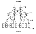
従来のネットワークトポロジーの実装は、図1に示すような階層的ツリー構造で編成された完全に独立したスイッチに基づく。コアスイッチ2は、スイッチィング容量が非常に大きな超高速の少数ポートである。第2層は、多くのポートを含む中容量スイッチである集約スイッチ4を用いて実装され、第3層は、低速でポート数が多く(40/48)低容量のエッジスイッチ6を用いて実装される。通常、エッジスイッチはレイヤ2であり、集約ポートはレイヤ2及び/又はレイヤ3であり、一般にコアスイッチはレイヤ3である。この実装は、あらゆるサーバ8に、図示の例では最大6ホップリンク(コアスイッチ2までの3ホップと、宛先サーバ8までの3つの下りホップ)でのいずれかのサーバ接続性を提供する。また、このような階層構造は、通常、冗長信頼性のために二重化される。例えば、図1を参照すると、二重化されていなければ、右端のエッジスイッチ6が故障した場合、右端のサーバ8との接続性が存在しなくなる。コアスイッチ2が故障すると、データセンタ全体の接続性障害が生じるので、少なくともコアスイッチ2は二重化される。明らかな理由により、この方法には、将来的なCDCの課題に対処する上で大きな制限がある。例えば、各スイッチが完全に自己完結型であることにより、複雑性、広い床面積利用、ヒューマンエラーが生じやすい複雑なケーブル配線及び手動スイッチの構成/プロビジョニング、並びにエネルギーコストの増加が加わる。
Traditional network topology implementations are based on completely independent switches organized in a hierarchical tree structure as shown in FIG. The
一方で、データセンタにおけるスイッチングの拡張性、信頼性、容量及び遅延を改善する多くの試みが行われてきた。例えば、統合制御プレーン(例えば、Juniper Networks社製のQFabricシステムスイッチ、例えば、http://www.juniper.net/us/en/products−services/switching/qfabric−system/を参照)を用いてさらに複雑なスイッチング解決策を実装する努力が行われてきたが、このようなシステムは、依然として従来の階層アーキテクチャを使用し、これを維持するものである。また、システムユーザの数、並びに記憶し、アクセスし、処理すべきデータ数の急激な増加を考えると、コンピュータネットワークシステムの性能要件を決定する際には、処理能力が最も重要な要素となってきている。サーバ性能は絶えず改善されているが、1つのサーバでは、このニーズを満たすほど十分に強力ではない。このことが、並列処理の使用が最重要になってきた理由である。この結果、大部分がnorth−southトラフィックフローであったものが、現在では、最大80%もの多くの事例において主にeast−westトラフィックフローになってきている。このトラフィックフローの変化にも関わらず、ネットワークアーキテクチャは、このモデルにとって最適となるように進化していない。従って、並列処理通信中のCPU間の相互作用速度を決定するのは、依然として(コンピュータノード(サーバ)を相互接続する)通信ネットワークのトポロジーである。 On the other hand, many attempts have been made to improve the scalability, reliability, capacity and delay of switching in data centers. For example, using an integrated control plane (eg, see Qfabric system switches from Juniper Networks, eg, http://www.juniper.net/us/en/products-services/switching/qfabric-system/ ) While efforts have been made to implement complex switching solutions, such systems still use and maintain traditional hierarchical architectures. Considering the number of system users and the rapid increase in the number of data to be stored, accessed and processed, processing power has become the most important factor in determining the performance requirements of computer network systems. ing. While server performance is constantly improving, a single server is not powerful enough to meet this need. This is why the use of parallel processing has become paramount. As a result, what has been mostly north-south traffic flows is now mostly east-west traffic flows in many cases up to 80%. Despite this change in traffic flow, the network architecture has not evolved to be optimal for this model. Thus, it is still the topology of the communication network (which interconnects computer nodes (servers)) that determines the interaction speed between CPUs during parallel processing communications.
east−westトラフィック通信を増加させるニーズは、新しいフラットなネットワークアーキテクチャ、例えばトロイダル/トーラスネットワークの形成をもたらした。トーラス相互接続システムは、並列コンピュータシステムにおいてネットワークノード(サーバ)をメッシュ状に接続するネットワークトポロジーである。トーラストポロジは、ノードを2次元、3次元又はそれよりも多くの(N)次元で配置することができ、この配置では、プロセッサ/サーバが最も近い隣接プロセッサ/サーバに接続され、アレイの反対端のプロセッサ/サーバ同士が接続されたアレイとして視覚化することができる。このように、N次元のトーラス構成では、各ノードが2N個の接続を有する(図2に、3Dトーラス相互接続の例を示す)。トーラストポロジにおける各ノードは、短いケーブルを介して隣接ノードに接続されているので、並列処理中のネットワーク遅延が少ない。実際に、トーラストポロジでは、あらゆるノード(サーバ)に最小のホップ数でアクセスすることができる。例えば、3×3×3×4の構造(108ノード)を実装する4次元トーラスでは、any−to−any接続を提供するために必要なホップ数は平均2.5ホップである。図4に示す6×6の2−Dトーラスの例に、角のノード1.6から他の全35個のノードに到達するのに必要な最小ホップ数を示している。図示のように、ノード1.6からいずれかの宛先に到達するのに必要なホップ数は、3ホップ(10ノード)を頂部とし、一般に5ホップ(4ノード)及び1ホップ(4ノード)をそれぞれ底部とする釣鐘曲線としてプロットすることができる。 The need to increase east-west traffic communication has led to the formation of new flat network architectures, such as toroidal / torus networks. The torus interconnection system is a network topology in which network nodes (servers) are connected in a mesh shape in a parallel computer system. Torus topology allows nodes to be arranged in 2D, 3D or more (N) dimensions, where the processor / server is connected to the nearest neighbor processor / server and the opposite end of the array Can be visualized as an array of connected processors / servers. Thus, in an N-dimensional torus configuration, each node has 2N connections (an example of a 3D torus interconnect is shown in FIG. 2). Each node in the torus topology is connected to an adjacent node via a short cable, so that the network delay during parallel processing is small. In fact, in a torus topology, every node (server) can be accessed with a minimum number of hops. For example, in a 4D torus that implements a 3 × 3 × 3 × 4 structure (108 nodes), the average number of hops required to provide an any-to-any connection is 2.5 hops. The 6 × 6 2-D torus example shown in FIG. 4 shows the minimum number of hops required to reach all the other 35 nodes from the corner node 1.6. As shown, the number of hops required to reach any destination from node 1.6 is 3 hops (10 nodes) at the top, typically 5 hops (4 nodes) and 1 hop (4 nodes). Each can be plotted as a bell curve with the bottom.
残念ながら、大規模トーラスネットワークの実装は、大規模実装の構築に何年も掛かり、ケーブル配線が複雑であり(各ノードにつき2N個の接続)、拡張が必要な場合に変更コストが掛かり面倒となり得るので、DC又はCDCにおける商用展開には実用的でなかった。しかしながら、処理能力のニーズが商業上の欠点を上回る場合には、スーパーコンピュータにおけるトーラストポロジの実装が非常に功を奏してきた。この点、IBM社のBlue Geneスーパーコンピュータは、64個のキャビネットが65,536個のノード(131,072個のCPU)を収容して数ペタフロップの処理能力を提供する3−Dトーラス相互接続ネットワークの例であり(図3の例示を参照)、富士通(Fujitsu)社のPRIMEHPC FX10スーパーコンピュータシステムは、98,304個のノードを含む1,024個のラックに収容された6−Dトーラス相互接続の例である。上記の例は、トーラストポロジに対応するものであるが、他のフラットネットワークトポロジにも等しく適用可能である。 Unfortunately, the implementation of a large-scale torus network takes many years to build a large-scale implementation, the cabling is complicated (2N connections per node), and it is cumbersome and costly to change if expansion is required. As such, it was not practical for commercial deployment in DC or CDC. However, implementations of torus topologies in supercomputers have been very successful when processing power needs exceed commercial shortcomings. In this regard, IBM's Blue Gene supercomputer is a 3-D torus interconnection network in which 64 cabinets accommodate 65,536 nodes (131,072 CPUs) and provide several petaflops of processing power. (See illustration in FIG. 3), the Fujitsu PRIMEHPC FX10 supercomputer system is a 6-D torus interconnect housed in 1,024 racks containing 98,304 nodes. It is an example. The above example corresponds to a torus topology, but is equally applicable to other flat network topologies.
本発明は、トーラス又は高基数ネットワーク構造におけるノードからノードへのデータパケットのトラバース及びルーティングという重要な問題に、より具体的に対処するものである。この点、ネットワークにおいてデータパケットが送信元から宛先に到達するために取る実際の経路を決定するのはルーティングである。本明細書における遅延とは、ネットワークにおいてパケットが宛先に到達するのに掛かる時間のことを意味し、一般にヘッダが送信元ノードの入力に到着した時点から宛先ノードの入力に到着した時点までが測定される。ホップ数は、送信元と宛先との間でトラバースしたリンク数又はノード数を意味し、遅延を決定するための近似値を表す。スループットは、ネットワークが入力ポート/ノード毎に受け入れる、ビット/秒の単位で測定したデータ率である。 The present invention more specifically addresses the important issue of traversing and routing of data packets from node to node in torus or high radix network structures. In this regard, it is routing that determines the actual path that a data packet takes to reach the destination from the source in the network. Delay in this specification means the time it takes for a packet to reach the destination in the network, and is generally measured from the time when the header arrives at the input of the source node to the time when it arrives at the input of the destination node. Is done. The number of hops means the number of links or nodes traversed between the transmission source and the destination, and represents an approximate value for determining the delay. Throughput is the data rate measured in bits per second that the network accepts per input port / node.
ルーティングによってトラフィックがノード間で均等に分散(負荷バランシング)した結果、ホットスポットの発達(使用量/需要量が所望の又は許容できる閾値を超える経路又はノード領域)が避けられ、(2又は3以上のノードが同じ配線又は経路を介してメッセージ又はパケットを同時に送信しようと試みる際の)競合が最小化され、これによってネットワーク遅延及びスループットが改善された時に有用な目標が達成される。従って、選択されたルートは、ノードからノードへのホップ数に影響し、これによってルートが最適でない時にはエネルギー消費量に影響する可能性もある。 Routing distributes traffic evenly among nodes (load balancing), thus avoiding hotspot development (routes / node areas where usage / demand exceeds a desired or acceptable threshold) (2 or more) A useful goal is achieved when contention nodes are trying to send messages or packets simultaneously over the same wire or path, thereby improving network delay and throughput. Thus, the selected route affects the number of hops from node to node, which may affect energy consumption when the route is not optimal.
トポロジーは、平均最小ホップ数及びノード間距離に影響するので、ネットワークが動作するトポロジーは、明らかに遅延にも影響する。例えば、トーラスでは、パケットが宛先に到達するために取ることができる経路が複数存在する(すなわち、トーラスにおいては、「経路多様性」が存在する)だけでなく、いずれかの送信元と宛先との対間の最短距離経路も複数存在する。一例として、図5に、2−DトーラスメッシュにおいてパケットがノードS11からノードD12に到達するために取ることができる3つの最短ルート(3ホップ)との例と、それよりも長い5ホップの第4のルートとを示す。ルーティングを通じて行われる経路の消費は、トポロジーのみに基づいて静的に行われ、送信元ルーティング(ソースルーティング)は、ホップ毎にパケット送信元と宛先との対に基づいて動的に行われる。 Since the topology affects the average minimum number of hops and the distance between nodes, the topology in which the network operates clearly affects the delay. For example, in a torus, there are multiple paths that a packet can take to reach a destination (ie, in a torus, there is “path diversity”), as well as any source and destination There are also a plurality of shortest distance paths between pairs. As an example, FIG. 5 shows an example of three shortest routes (3 hops) that a packet can take to reach node D12 from node S11 in a 2-D torus mesh, and a longer 5-hop first. 4 routes. The route consumption performed through the routing is statically performed based only on the topology, and the source routing (source routing) is dynamically performed based on the pair of the packet source and the destination for each hop.
経路の多様性を利用するルーティング法は、ネットワークにおける耐障害性及び負荷バランシングが良好である。しかしながら、ルーティング法は、必ずしもこのような目標を達成するわけではなく、一般に、決定論的ルーティング、無情報(oblivious)ルーティング及び適応的ルーティングという3つのクラスに分割することができる。決定論的ルーティングは、所与のノード対間の(単複の)ルートが、現在のネットワーク状態に関わらず(すなわち、ネットワークトラフィックに関わらず)予め決定されることを意味する。決定論的ルーティングの例には、ノードAからノードBへの全てのメッセージが常に同じ経路をトラバースするDimension Orderルーティング(DOR)がある。具体的には、メッセージが次元毎にトラバース(X−Yルーティング)することにより、1つの次元内の宛先に一致する縦座標に到達してから次の次元に切り替わる。一例として、図6を用いてDORを示すことができ、この例では、パケットが、最初にノード1からノード5を通ってノード9に至るまで必要な限り第1の次元(X)に沿ってトラバースし、その後、第2の次元(Y)に沿って宛先ノード10に至る。このようなルーティングは、一般に実装が容易であってデッドロックが存在しないが(デッドロックとは、送信元から宛先まで経路に沿って無限サイクルが存在する状況を意味する)、経路の多様性を利用しておらず、従って負荷バランシングに乏しい。
The routing method using the diversity of routes has good fault tolerance and load balancing in the network. However, routing methods do not necessarily achieve such goals and can generally be divided into three classes: deterministic routing, oblivious routing, and adaptive routing. Deterministic routing means that the route (s) between a given pair of nodes is predetermined regardless of the current network state (ie regardless of network traffic). An example of deterministic routing is Dimension Order Routing (DOR) where all messages from Node A to Node B always traverse the same path. Specifically, the message traverses for each dimension (XY routing), so that the message is switched to the next dimension after reaching the ordinate corresponding to the destination in one dimension. As an example, FIG. 6 can be used to show the DOR, in which the packet is first along the first dimension (X) as long as necessary from
「無情報」なルーティングアルゴリズムは、ルーティング決定が、現在のネットワーク状態に関わらずランダムに行われるものである(決定論的ルーティングは、無情報ルーティングの一部である)。このことは、無情報ルーティングの実装が用意になり得ることを意味するが、やはりトラフィック及びネットワーク環境に適合することができない。周知の無情報ルーティング方法の例は、(当業者に周知の)Valiantアルゴリズムである。この方法では、ノードAからノードBに送られるパケットが、最初にノードAからランダム選択された(1ホップ離れた)中間ノードXに送られ、その後にノードXからノードBに送られる。再び図6を参照すると、Valiantアルゴリズムは、送信元ノード1から宛先ノード10までの中間ノードとしてノード2をランダムに選択することができ、すなわち、例えば経路1−2−3−7−11−10をルーティング目的で使用することができる。このアルゴリズムは、一般にあらゆるトラフィックパターンをランダム化するものであり、全てのパターンが均等にランダムであるように見えるので、ネットワーク負荷のバランスは適正である。実際に、Valiantアルゴリズムは、一般にほとんど全てのトポロジーに基づくあらゆるトラフィックパターンについて負荷をバランシングできると考えられてきた。しかしながら、1つの問題点は、一般にValiantによるルートは非最短であり(最短ルートとは、送信元と宛先との間の必要なホップ数が最も少ない経路のことである)、この結果、しばしばホップ数が大幅に増加し、これによってネットワーク遅延がさらに増し、エネルギー消費量が増加する可能性もある点である。しかしながら、輻輳が最小限に抑えられたネットワークなどの例外もある。非最短ルーティングでは、追加のノードをトラバースする際の遅延、及び恐らくは消費電力が大幅に増加する恐れがある一方で、輻輳を経験するネットワークでは、非最短ルーティングが実際にノード又はホットスポットを避ける役に立ち、これによって実際に遅延が短くなる場合もある。
An “informative” routing algorithm is one in which routing decisions are made randomly regardless of the current network state (deterministic routing is part of informative routing). This means that an information-free routing implementation can be prepared, but still cannot adapt to traffic and network environments. An example of a well known no information routing method is the Variant algorithm (well known to those skilled in the art). In this method, a packet sent from node A to node B is first sent to intermediate node X randomly selected (one hop away) from node A, and then sent from node X to node B. Referring again to FIG. 6, the Variant algorithm can randomly select
しかしながら、最短ルートが望ましい場合又は必要な場合、Valiantアルゴリズムは、最小四分円内に中間モードが存在しなければならない旨を規定することにより、アルゴリズムのランダムな決定を最短ルート/最短経路に制限するように修正することもできる。一例として、図6を参照すると、(宛先ノード10を有する)ノード1の最小四分円はノード2、5及び0を含み、通常のホップ数は3になる。Valiantアルゴリズムは、ホットスポットが発達する可能性を下げるいくつかのレベルの経路選択ランダム化を提供する。しかしながら、Valiantルーティングでは、デッドロックが存在しないのはDORルーティングと併用した場合のみであり、Valiantルーティング自体は負荷バランシング及びホットスポット回避と共に成立しないという、このような効率に影響するさらなる難しい問題点も存在する。
However, when the shortest route is desirable or necessary, the Variant algorithm limits the algorithm's random decision to the shortest route / shortest route by specifying that an intermediate mode must exist in the minimum quadrant. It can also be modified to As an example, referring to FIG. 6, the minimum quadrant of node 1 (with destination node 10) includes
適応的ルーティングアルゴリズムは、ルーティング決定がネットワーク又はネットワークトラフィックの状態に基づくアルゴリズムである。これらのアルゴリズムは、一般にフロー制御機構を伴い、この点において、多くの場合バッファ占有率が使用される。適応的ルーティングは、(コストパフォーマンスの良い)グローバルノード情報を使用することも、或いは、例えばネットワーク輻輳を測るためのキュー占有率を含む、ローカルノードのみからの情報を使用することもできる。ローカルノードのみからの情報を使用する問題点は、選択が最適以下になることもあるという点である。適応的ルーティングは、最短経路に制限することも、或いはライブロック(すなわち、パケット移動が宛先まで進まないデッドロックに類似する状況であり、しばしばリソースの枯渇を招く)の恐れもある非最短経路を採用することによって完全に適応的とする(すなわち、最短経路を取ることに制限されない)こともできる。この問題は、パケット毎に一定数の誤ルートを可能にし、何度もルートを誤ったパケットに高優先度を与えることによって克服できることもある。適応的ルーティングの別の問題点は、パケットが同じ順序で宛先に到着する必要があり、そうでなければ、パケット順序変更機構を実装する必要があるという、データパケットの順序が維持される問題を引き起こし得る点である。 An adaptive routing algorithm is an algorithm in which routing decisions are based on network or network traffic conditions. These algorithms generally involve a flow control mechanism, and in this respect buffer occupancy is often used. Adaptive routing can use global node information (which is cost effective), or it can use information from only the local node, including, for example, queue occupancy to measure network congestion. The problem with using information from only the local node is that the selection may be suboptimal. Adaptive routing can limit non-shortest paths that can be restricted to shortest paths or live-locked (ie, a situation similar to a deadlock where packet movement does not proceed to the destination, often resulting in resource exhaustion). It can also be made fully adaptive (ie, not limited to taking the shortest path). This problem may be overcome by allowing a certain number of misroutes per packet and giving high priority to packets misrouted many times. Another problem with adaptive routing is that the order of data packets is maintained, where packets need to arrive at their destination in the same order, otherwise packet reordering mechanisms must be implemented. It can be caused.
最後に、重要なこととして、送信元テーブル又はローカルテーブルによってルーティングを実装できる点に言及する。送信元テーブルを使用すると、送信元においてルート全体が規定され、このルートをパケットヘッダに埋め込むことができる。従って、各ノードにおいてホップ毎にルートを固定又は決定する必要がないので、遅延が最短になる。送信元テーブルは、故障を管理できるように、またルートがランダムに選択(すなわち、無情報ルーティング)された時には負荷バランシングを高めることができるように、宛先毎に複数のルートを規定することもできる。一方、ローカルノードテーブルを使用すると、採用されるルーティングテーブルが小型になる。しかしながら、パケットが進む次のステップが各ノードにおいて決定され、これによってホップ毎の遅延が加わる。 Finally, it is important to note that routing can be implemented by source tables or local tables. When the transmission source table is used, the entire route is defined at the transmission source, and this route can be embedded in the packet header. Accordingly, there is no need to fix or determine a route for each hop at each node, so that the delay is minimized. The source table can also define multiple routes per destination so that failures can be managed and load balancing can be improved when routes are randomly selected (ie no information routing). . On the other hand, when the local node table is used, the employed routing table becomes small. However, the next step in which the packet proceeds is determined at each node, which adds a hop-by-hop delay.
本発明は、先行技術の欠点を克服し、トーラス又は高基数ネットワークトポロジーにおける周知のパケットルーティング方法を改善しようとするものである。 The present invention seeks to overcome the shortcomings of the prior art and improve known packet routing methods in torus or high radix network topologies.
本発明は、1つの態様において、低遅延、高スループット、並びにホットスポット及びデッドロックの回避をもたらすようにトーラスメッシュ又は高基数トポロジーにわたってデータパケットをルーティングする新規方法を提供する。 The present invention, in one aspect, provides a novel method for routing data packets across a torus mesh or high radix topology to provide low latency, high throughput, and avoidance of hot spots and deadlocks.
本発明は、さらに別の態様において、トーラス又は高基数構造に、トラフィックの非相関化(ランダム化)、高効率な帯域幅割り当て、負荷バランシング及びトラフィックエンジニアリングを実装する方法を提供する。 In yet another aspect, the present invention provides a method for implementing traffic decorrelation (randomization), highly efficient bandwidth allocation, load balancing and traffic engineering in a torus or high radix structure.
本発明は、1つの実施形態において、直接相互接続ネットワークにおいて送信元ノードから宛先ノードにパケットをルーティングするコンピュータ実装方法であって、ネットワークトポロジーにおける全てのノードと、各ノードの全ての出力ポートとを発見するステップと、ネットワークトポロジーにおける発見されたノード及び出力ポートを最短経路のルーティング計算に含めるために、前記ノード及びポートをトポロジーデータベースに含めるステップと、トポロジーデータベースに含まれているノード及び出力ポートに基づいて、ネットワークトポロジーにおける各ノードの全ての出力ポートから他の全てのノードへの最短経路を計算するステップと、各ノードにおいて、ネットワークトポロジーにおける前記各ノードの全ての出力ポートから他の全てのノードへの最短経路を含む送信元ルーティングデータベースを生成するステップと、送信元ノードにおいてパケットを受け取るステップと、前記受け取ったパケットの各々が、その後に送信元ノードの出力ポートにおいてフリットに分割されて送信元ノードの出力ポートから宛先ノードまでの最短経路に沿って分散され、この結果、パケットがネットワークトポロジーにおける別ルートに沿って分散されるように、受け取ったパケットを、送信元ノードの出力ポートにラウンドロビン方式又は重み付きラウンドロビン方式で送信するステップと、宛先ノードにおいて、パケットをその元々の形態及び順序に従うように再構築して順序変更するステップとを含むコンピュータ実装方法を提供する。 The present invention, in one embodiment, is a computer-implemented method for routing packets from a source node to a destination node in a direct interconnect network, comprising all nodes in the network topology and all output ports of each node. Discovering, and including the discovered node and output port in the network topology in the shortest path routing calculation, including the node and port in the topology database; and the nodes and output ports included in the topology database Based on calculating the shortest path from all output ports of each node in the network topology to all other nodes, and in each node, all output ports of each node in the network topology. Generating a source routing database including the shortest path from the host to all other nodes; receiving a packet at the source node; and each of the received packets thereafter at an output port of the source node The received packet is divided into flits and distributed along the shortest path from the output port of the source node to the destination node, so that the packet is distributed along another route in the network topology. A computer-implemented method comprising: transmitting to a node output port in a round-robin or weighted-round-robin manner; and reconfiguring and reordering packets at a destination node to conform to their original form and order provide.
本発明は、さらなる実施形態において、ワームホール切り替えを用いてフリットを宛先ノードに転送するパケットルーティング方法を提供する。 In a further embodiment, the present invention provides a packet routing method for forwarding flits to a destination node using wormhole switching.
以下、添付図面を参照しながら本発明の実施形態を一例として説明する。 Hereinafter, an embodiment of the present invention will be described as an example with reference to the accompanying drawings.
本発明は、トーラスメッシュ又は高基数配線を利用して、データセンタアプリケーションの直接相互接続切り替えを実装するものである。具体的には、本発明は、2014年8月29日に出願された「コンピュータネットワークにおける直接相互接続スイッチ配線及び成長の管理方法及び装置(Method and Apparatus to Manage the Direct Interconnect Switch Wiring and Growth in Computer Networks)」という名称の関連するカナダ国特許出願公開第2014/000652号に記載されているトーラスシステムとの使用が特に有用である。このようなアーキテクチャは、単一の切り替え領域内に数万台のサーバを有する高性能ネットワーク相互接続を提供することができる。 The present invention implements direct interconnection switching of data center applications using torus mesh or high radix wiring. Specifically, the present invention was filed on Aug. 29, 2014, “Method and Apparatus to Manage the Direct Interconnect Switch Wiring and Growth in Computer,” and “Management Method for Direct Interconnect Switch Wiring and Growth in Computer Network. Particularly useful is the use of the torus system described in the related Canadian Patent Application No. 2014/000652 entitled “Networks”. Such an architecture can provide a high performance network interconnect with tens of thousands of servers in a single switching area.
スイッチを制御するソフトウェアは、Software Defined Networkモデルに従う。スイッチコントロールプレーン(スイッチOS)は、独立サーバ上で動作するが、各PCIeカード上で動作する分散処理と密接に相互作用することが好ましい。図11を参照すると、主要ソフトウェアコンポーネントが、トポロジー発見(TD)、トポロジーにわたるパケットルーティング(SR)、ワームホール切り替え(WS)、フロー制御(FC)機構、並びにスイッチ状態モニタリング及びスイッチ管理を含む。TDコンポーネントは、基本的にトーラスメッシュ内のノードの存在(又は不在)を発見することに関与し(及びこれによりノードの存在に基づいて考えられる経路の更新を可能にし)、SRコンポーネントは、送信元ルーティング計算(送信元ノードの全てのポートからいずれかの宛先ノードへの利用可能な全ての経路)に関与し、WSコンポーネントは、フリットヘッダに含まれる最短遅延の経路ベクトルに基づく、トーラスにわたるフリット操作(全てのノードにおけるカットスルーモデル)に関与し、FCコンポーネントは、入力キューイング機構を通じてトラフィックを規制するためにトーラスリンクの利用及び送信元への制御メッセージに関与し、スイッチ状態モニタリングコンポーネントは、トラフィックバランシング、障害状況におけるトラフィックのルート変更、及びスイッチ成長のサポートに関与し、スイッチ管理コンポーネントは、全ての相互接続サーバ、外部との全ての相互接続I/Oリンク及び接続性状態を含む、スイッチの完全なイメージを維持することに関与する。 The software that controls the switch follows the Software Defined Network model. The switch control plane (switch OS) operates on an independent server, but preferably interacts closely with distributed processing that operates on each PCIe card. Referring to FIG. 11, the main software components include topology discovery (TD), packet routing across topology (SR), wormhole switching (WS), flow control (FC) mechanism, and switch state monitoring and switch management. The TD component is basically responsible for discovering the presence (or absence) of a node in the torus mesh (and thus enabling possible path updates based on the presence of the node), and the SR component Involved in the original routing computation (all available routes from all ports of the source node to any destination node), the WS component performs a flit across the torus based on the shortest delay path vector contained in the flit header Involved in the operation (cut-through model in all nodes), the FC component is responsible for the use of torus links and control messages to the source to regulate traffic through the input queuing mechanism, and the switch state monitoring component Traffic balancing, failure Involved in supporting traffic rerouting and switch growth in the context, the switch management component provides a complete image of the switch, including all interconnected servers, all interconnected I / O links and connectivity status to the outside Involved in maintaining.
本発明は、主に本発明の新規のトポロジー発見(TDコンポーネント)及びルーティングプロトコル(SRコンポーネント)に関し、主要機能は、カナダ国特許出願公開第2014/000652号に開示されている新規のスイッチアーキテクチャにおける実装に特に有用である。トーラス構造を通じてデータパケットをルーティングする従来の実装では、トラフィックが宛先ノードにわたってランダムに分散されるという非明示的な想定を行っているが、実際の実装では、単一の送信元/単一の宛先において最大容量の連続パケットフローが生じた場合に、トーラスメッシュにわたるパケット転送能力を完全に無効にする容量を有するホットスポットの発達がトーラスにわたって伝搬することによって実際にスイッチ障害が示された。従って、本発明は、(いずれかの送信元から(相関性の高い)いずれかの宛先までの大量のフロー、又はランダムに分散した宛先へのトラフィック(典型的なインターネットトラフィック)に関わらず)あらゆるタイプのトラフィックの性能問題及びホットスポットの発達に対処するために、トーラス又は高基数ネットワークなどの直接相互接続ネットワークトポロジーのためのルーティングの最適化及び実装についてさらに具体的に言及する。上述したようなトーラス内でパケットをルーティングする既知の方法とは対照的に、本発明は、トポロジー内の全てのノードを発見して更新する方法、並びに各ノードにおける全ての出力ポート(例えば、x+、x−、y+、y−、z+、z−、w+及びw−)上の全ての宛先ノードへの(単複の)最短経路を計算することより、パケットを各出力ポートからの経路に沿ってラウンドロビン方式又は重み付きラウンドロビン方式で(すなわち、複数の別の経路を奨励して)分散させ、帯域幅及びトラフィック分配を増加させてホットスポットを回避するパケットルーティング方法について説明する。フロー制御(FC)機構を用いて、パケットルーティングのための出力ポートの選択を、単純なラウンドロビンによる連続的な送信元ノード出力ポート選択(すなわち、最初にポートx+、次にポートx−、その後にy+、y−、z+、z−、w+及びw−)から、FCによってビジーとして識別されたリンクをスキップし、或いはこれらのポート上のトラフィックを最大リンク容量の低率(例えば、10%)に減少させる重み付きラウンドロビン方式に適応的に変更する。 The present invention mainly relates to the novel topology discovery (TD component) and routing protocol (SR component) of the present invention, the main function of which is in the novel switch architecture disclosed in Canadian Patent Application Publication No. 2014/000652. It is particularly useful for implementation. Traditional implementations that route data packets through a torus structure make an implicit assumption that traffic is randomly distributed across the destination nodes, but in a real implementation, a single source / single destination When a maximum capacity continuous packet flow occurs at, a switch failure was actually indicated by the propagation of hot spots with the capacity to completely disable packet forwarding capabilities across the torus mesh. Thus, the present invention can be applied to any flow (regardless of a large number of flows from any source to any (highly correlated) destination, or traffic to a randomly distributed destination (typical Internet traffic)). In order to address the type of traffic performance issues and hot spot development, more specific mention is made of routing optimization and implementation for direct interconnect network topologies such as torus or high radix networks. In contrast to known methods for routing packets within a torus as described above, the present invention provides a method for discovering and updating all nodes in a topology, as well as all output ports (eg, x +) at each node. , X-, y +, y-, z +, z-, w +, and w-) by computing the shortest path (s) to all destination nodes, along the path from each output port A packet routing method is described that distributes in round robin or weighted round robin (ie, encourages multiple alternative paths) to increase bandwidth and traffic distribution to avoid hot spots. Using a flow control (FC) mechanism, the selection of output ports for packet routing is done by simple round robin continuous source node output port selection (ie first port x +, then port x-, then Y +, y-, z +, z-, w + and w-) to skip links identified as busy by the FC or traffic on these ports to a low percentage of maximum link capacity (eg 10%) It is adaptively changed to the weighted round robin method to be decreased.
宛先ノードでは、データパケット順序変更が実装される。このような方法は、カナダ国特許出願公開第2014/000652号に開示され本明細書でさらに説明する新規のノード(サーバ)発見方法を特に活用することができる。従って、本発明は、(いずれかの送信元から(相関性の高い)いずれかの宛先までの大量のフロー、又はランダムに分散した宛先へのトラフィック(典型的なインターネットトラフィック)に関わらず)あらゆるタイプのトラフィックの性能問題及びホットスポットの発達に対処するために、トーラス又は高基数ネットワークなどの直接相互接続ネットワークトポロジーのパケットルーティング最適化の問題に対処する。 At the destination node, data packet reordering is implemented. Such a method can take particular advantage of the novel node (server) discovery method disclosed in Canadian Patent Application Publication No. 2014/000652 and further described herein. Thus, the present invention can be applied to any flow (regardless of a large number of flows from any source to any (highly correlated) destination, or traffic to a randomly distributed destination (typical Internet traffic)). To address the performance issues of types of traffic and the development of hot spots, address the issue of packet routing optimization in direct interconnect network topologies such as torus or high radix networks.
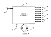
まず第1に、図7に、外部にアクセスするためのI/Oポート13(N−Sインターフェイス)、4Dトーラス相互接続ポート14、コンピュータサーバにアクセスするためのPCIeポート15及び制御19という全てのポートを有する高速ネットワークインターフェイスカード10の高水準図を示す。当業者であれば、本発明は、これより少ない又は多くのポートを有するHNIカードと協働することもでき、他のトーラス又は(例えば「ドラゴンフライ」などの)高基数トポロジーに関連することもできると理解するであろう。
First of all, FIG. 7 shows all of the I / O port 13 (N-S interface) for accessing the outside, the 4D
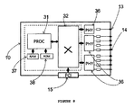
図8には、本発明のシステムによる、RAM37及びROM38を含むプロセッサ31と、切り替えブロック32と、物理インターフェイス装置36と、トーラス相互接続ポート14と、I/Oポート13と、PCIeポート15とを含む主要機能ブロックを有するHNIカード10の高水準図を示す。この実施形態の物理的実装は、マルチコアプロセッサに付属のメモリとPHY装置とを取り付けてトーラス相互接続を実装したものに基づく。切り替え機能は、プロセッサのハードウェアアクセラレーション支援機能を用いて複数のキュー操作をサポートするソフトウェアで実装される。当業者であれば、本発明は、物理的実装が異なる場合、すなわち切り替え機能アクセラレーションをFPGA又はASICで実装した場合でも機能し、或いは切り替え機能に使用するカードと同じカード上にプロセッサが存在する必要はないと理解するであろう。
FIG. 8 shows a
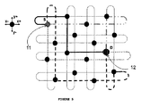
図10は、本発明によるパケットルーティングの説明において使用する単純な2Dトーラス配線図である。図示のように、この構造は、全体を通じて各接続の長さが等しい折り畳んだ2Dトーラスである。この図における各ノードは、サーバに収容された(上述した)PCIeスイッチカードを介して相互接続されたサーバを表す。この図には、送信元ノードSにおいて計算される、送信元ノードS(2.4)のポートから宛先ノードD(5.2)への、様々な次元(x+、x−、y+、y−)において開始する(共通のリンク又はノードが存在しない)最短最大の非同一経路を示している。この点、図10には、5ホップという最小ホップ数を有する3つの計算された経路及びルーティングベクトル((S)2.4から(x+、x+、x+、y−、y−)、(S)2.4から(y−、y−、x+、x+、x+)、及び(S)2.4から(x−、x−、y−、y−、x−))を示しているが、7ホップという非最小ホップ数を有する別の経路((S)2.4から(y+、y+、y+、x+、x+、x+、y+)も計算される。送信元SとDノードとの間の大量のトラフィックを想定すると、パケット/フリットは、ラウンドロビン又は重み付きラウンドロビン方式で各送信元ノードSの出力ポートから開始して各出力ポートからの経路に沿って宛先ノードに向かう最短経路上でノードDに送信され、これによって一方では複数の経路を用いて帯域幅を増加させ、トラフィックを分散させてホットスポットの発達を避ける(送信元ノードにおいて出力ポートの重み付きラウンドロビンを選択すると、いくつかの経路に沿ったパケット数が増加する)。各ノードでは、第1のホップ以外に、リンク又はノード障害の際にルートが必要に応じてトラフィック輻輳及びホットスポットを克服するのに役立つ別の独立経路を提供するように、第2の別ルートを計算して記憶することもできる。この方法は、負荷バランシングの目的でトーラス又は高基数ネットワークにわたってトラフィックを分散するが、パケット順序変更を導入することもできる。例えば、y+から開始する経路(図10)は、最短経路(5ホップ)よりも2ホップ長いので、この経路上で送信される全てのパケットはさらに遅れて到着し、これによってパケット順序変更問題が生じることがある。従って、本発明によれば、宛先ノードにおいてパケットを順序変更する必要がある。このことは、当業者の技術範囲内である。 FIG. 10 is a simple 2D torus wiring diagram used in the description of packet routing according to the present invention. As shown, this structure is a folded 2D torus where the length of each connection is equal throughout. Each node in this figure represents a server interconnected via a PCIe switch card (described above) housed in the server. This figure shows the different dimensions (x +, x−, y +, y−) from the port of the source node S (2.4) to the destination node D (5.2), calculated at the source node S. ), The shortest maximum non-identical path (no common link or node). In this regard, FIG. 10 shows three calculated routes and routing vectors ((S) 2.4 to (x +, x +, x +, y−, y−), (S) with a minimum number of hops of 5 hops. 2.4 to (y−, y−, x +, x +, x +) and (S) 2.4 to (x−, x−, y−, y−, x−)) Another route ((S +) 2.4 (y +, y +, y +, x +, x +, x +, y +) with a non-minimum hop number of hops is also calculated. A large amount between the source S and the D node. Assuming the traffic of the packet, the packet / frit is started from the output port of each source node S in the round robin or weighted round robin method, and the node is on the shortest path toward the destination node along the path from each output port. D, which on the one hand has multiple routes Use to increase bandwidth and distribute traffic to avoid hotspot development (selecting output port weighted round robin at the source node increases the number of packets along some paths). At the node, in addition to the first hop, a second alternate route is provided so that in the event of a link or node failure, the route provides another independent path that helps to overcome traffic congestion and hot spots as needed. This method distributes traffic across a torus or high radix network for load balancing purposes, but can also introduce packet reordering, eg, a path starting from y + (FIG. 10 ) Is 2 hops longer than the shortest route (5 hops), so all packets sent on this route are Arrive later, which can lead to packet reordering problems, so according to the present invention, it is necessary to reorder packets at the destination node, which is within the scope of those skilled in the art. is there.
パケット分割の高水準図を示す図9を参照すると、重要なこととして、直接相互接続トーラス又は高基数ネットワークをトラバースするパケットは、ルーティング中にさらに小さなパケット(フリット)に分割される。パケットネットワークにおいてよく見られる問題である「ヘッドオブラインブロッキング」を、共有リソース(リンク及びバッファ)を用いて回避するために、トーラスメッシュ全体にわたってパケット分割が必要とされる。フリットのサイズは、オーバーヘッドの負担を最小化するようにトラフィックタイプによって決まり、実際の値の範囲は64〜512バイトである。重要なこととして、本発明は、とりわけEthernet(登録商標)パケット、Infinibandパケット、PCIeストリーム又はNVMeトランザクションに対処することができる。トーラス構造を横切るフリットは、トラフィックを透過的に搬送する。外部インターフェイスI/Oポート13は、トラフィックのタイプに固有のものであってユーザトラフィックを終了させ、トーラスを横切り「フリット」を介して宛先PCIeポート15にデータを透過的に転送する。重要なこととして、本発明は、(Ethernetフリットを介して)トーラスを横切るEthernetパケットに対処することができる。本明細書における主な利点は、Ethernetパケットのためのフリットがパケット描写機構を有しているので、フリットのサイズを変えられる点である。従って、フリットサイズは、64バイト(最小Ethernetパケットサイズ)〜512バイト(ペイロード及びヘッダ)まで可変である。パケットが512バイトよりも大きい場合、システムは、元のパケットを512バイトのフリット、すなわちヘッダフリット、ボディフリット及びテイルフリットに分割する。
Referring to FIG. 9, which shows a high level diagram of packet segmentation, importantly, packets traversing a direct interconnect torus or high radix network are segmented into smaller packets (flits) during routing. To avoid "head-of-line blocking", a common problem in packet networks, with shared resources (links and buffers), packet partitioning is required across the torus mesh. The size of the flit is determined by the traffic type so as to minimize the overhead burden, and the actual value range is 64 to 512 bytes. Importantly, the present invention can address, among other things, Ethernet packets, Infiniband packets, PCIe streams or NVMe transactions. A frit across the torus structure carries traffic transparently. The external interface I /
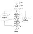
図12は、パケット分割方法を示すフローチャートである。HNIプロセッサは、ホスト(すなわち、PCIeインターフェイス)から新たなパケットを受け取ると(ステップ402)、ヘッダを抽出してパケットの宛先(ステップ404)及びルーティング経路を分析する。パケットは、この段階で分割ループに入る。バイトカウンタが初期化され(ステップ412)、パケットエンド(End of Packet:EOP)アナライザがEOPを検出し(ステップ405)、カウンタが476バイト以下である(すなわち、ペイロードが476バイト以下である)場合、パケットは、フリット生成器(ステップ407)、ヘッダ生成器(ステップ408)及び優先度決定ブロック(ステップ409)に送られる。その後、トーラスメッシュを横切って次のホップ(ネクストホップ)に送信するためにフリットを割り当て出口キューに挿入し(ステップ410)、新たなパケットが受け取られたかどうかを確認する(402)。各個々のフリット後にバイトカウンタを増分し(ステップ411)、フリット生成器にパケットフラグメントを送信し(ステップ407)、処理は、パケット内の最後のフリットに到達して送信するまで上述のステップをたどる。重要な見解として、トーラスリンク上のフリットは512バイト(476バイトのペイロード及び36バイトのヘッダ)であり、その後に8「アイドル」バイトが続くことが好ましい。パケットが476バイトに届かない場合、フリット(通常はテイルフリット)は512バイトよりも小さく、「アイドル」バイトを用いてパケット描写が行われる。図13に、パケット分割を通じたフリット生成を実装する疑似コードを示す。宛先では、トーラスヘッダを除去し、「Byte cnt」を用いて元々のパケット内のフリットをオフセットすることにより、フリットをパケットに組み立てる。当業者であれば、宛先ノードのために送信元毎のパケットキューを実装し、順序付けしたパケットフラグメントリストを作成し、パケットが完全に組み立てられたら元々の順序で放出すると認識するであろう。図14は、本発明によるルート計算を示すフローチャートである。本発明は、送信元ノードからいずれかの宛先ノードへの、送信元ノードの各出力ポート上で最大限に非同一である(共通のリンク及びノードが存在しない)全ての経路(送信元ルーティング)を計算するために図15の疑似コードも提供する。(アクティブなサーバ/ノード及びそのアクティブなポートを発見する)トポロジー更新機能412は、更新が検出されると直ぐに(すなわち、ノードの追加/削除時、又はノードに関連する重大な問題/故障の存在時には常に)ルート/経路計算を開始する(414)。本発明によれば、ステップ419(トポロジーリスト内で見つかった第1の宛先ノード)、その後にステップ420及び421(トポロジーリスト内の全ての宛先ノードを検索)に示すように、ダイクストラ法(Dijkstra algorithm)を用いてトポロジーから現在のノードと各宛先ノードとの間の最短経路が計算される(ステップ415)。ステップ422において、ステップ417によって影響を受ける全ての経路コストを初期値にリセットする。計算された送信元から宛先への最短経路は、送信元ルーティングデータベースに記憶され、この経路は、(非同一経路を提供するために)記憶された経路に属する全てのリンクのコストを無限に増加させることによってさらなる最短経路計算から削除され(417)、これには、トポロジーデータベースからノード及びリンクを削除して、非同一経路選択の目的で再利用しないように強制するという実用的効果がある。この処理は、全ての出力ポートが使用され、送信元ノードと宛先ノードとの間の考えられる全ての経路がデータベースに記憶されるまで継続する。次に、これらの結果が、最初に最短経路からルーティングを開始すべき各ノードのルーティングベクトルとして出力ルーティングテーブルにまとめられる(418)。最短経路の計算自体は、ルーティングプロトコルの実装において使用される周知の方法であるダイクストラ法を用いて実装することができる。本明細書では、全ての出力ポートにおいて最短経路が決定されて適宜使用される点が特に新規な点である。
FIG. 12 is a flowchart showing a packet division method. When the HNI processor receives a new packet from the host (ie, PCIe interface) (step 402), it extracts the header and analyzes the packet destination (step 404) and routing path. The packet enters a split loop at this stage. If the byte counter is initialized (step 412) and the end of packet (EOP) analyzer detects EOP (step 405) and the counter is less than 476 bytes (ie, the payload is less than 476 bytes) , The packet is sent to a flit generator (step 407), a header generator (step 408) and a priority determination block (step 409). Thereafter, a flit is inserted into the allocation exit queue for transmission across the torus mesh to the next hop (next hop) (step 410) to see if a new packet has been received (402). The byte counter is incremented after each individual flit (step 411), the packet fragment is sent to the flit generator (step 407), and the process follows the above steps until the last flit in the packet is reached and transmitted. . It is important to note that the flits on the torus link are 512 bytes (476 byte payload and 36 byte header), followed by 8 “idle” bytes. If the packet does not reach 476 bytes, the flit (usually tail flit) is less than 512 bytes, and packet delineation is done using “idle” bytes. FIG. 13 shows pseudo code for implementing flit generation through packet segmentation. At the destination, the torus header is removed and the flit is assembled into a packet by offsetting the flit in the original packet using “Byte cnt”. Those skilled in the art will implement a per-source packet queue for the destination node, create an ordered packet fragment list, and release it in its original order once the packets are fully assembled. FIG. 14 is a flowchart showing route calculation according to the present invention. The present invention is maximally non-identical (no common link and node) on each output port of the source node from the source node to any destination node (source routing) The pseudo code of FIG. 15 is also provided to calculate The topology update function 412 (discovering active servers / nodes and their active ports) may detect the presence of a significant problem / failure associated with a node as soon as an update is detected (ie, when a node is added / deleted, or a node) Start route / route calculation (sometimes always) (414). According to the present invention, as shown in step 419 (first destination node found in the topology list) followed by
図16に、ルーティング出力テーブルのフォーマットを示す。各ルートには、特定の経路のホップ数を表す数字、及びホップ毎に選択すべき出力ポートのリスト/ベクトルが付与される。具体的には、図16には、8つのポート(x+、x−、y+、y−、z+、z−、w+及びw−)を有する4−Dトーラス(8×8×8×8)における、送信元ノード番号1000から宛先ノード0への(ノード1000及びノード0の使用は例示にすぎない)ルートを表す出力テーブルのスナップショット例を示している。なお、第1の8つのルートグループの8つのルートのグループ分けにおける最初の出力選択(すなわち、x+、y+、z+、w+、x−、y−、z−及びw−)は、例えば送信元ノードの各出力ポートに対応する。8つの経路は、完全に非同一であり、5ホップ、7ホップ又は9ホップという異なる長さを有する。最も重要な特徴は、トラフィックの分散及び予測可能な性能を可能にする、トーラス全体にわたる経路分散である。図16の第2の8つの経路グループは、ルーティング経路の第2の代替例を表す。この方法では、多くの代替ルートを計算することができるが、距離(ホップ数)はますます長くなる。実用的な理由で、この方法は、必要に応じて8つの異なる経路である第1の選択肢のみを一般に記憶することができる。
FIG. 16 shows the format of the routing output table. Each route is given a number representing the number of hops of a specific route and a list / vector of output ports to be selected for each hop. Specifically, FIG. 16 shows in a 4-D torus (8 × 8 × 8 × 8) having eight ports (x +, x−, y +, y−, z +, z−, w + and w−). , Shows a snapshot example of an output table representing a route from the source node number 1000 to the destination node 0 (the use of the
図17は、本発明による、パケット切り替えにおいて使用するステップを示すフローチャートである。新たなパケットが出力キューにプッシュされると、パケット転送状態機械は、トーラスを横切って転送を開始する。この点、対象の出力ポート「k」(ポート1〜8、すなわち上述した出力ポート:x+、y+、z+、w+、x−、y−、z−及びw−)を用いて、(図18に示すように)ワームホールモデルに従ってフリットを転送し、図17に示すように、パケットの最後(テイルフリット)に達するまで、ヘッドフリット及び後続のフリット増分(ボディフリット)をポートkから同じ経路に沿って転送する。パケットの最後に達すると、カウンタkを増分して次の出力ポートを参照し、このワームホール切り替えモデルを用いて、次のパケット識別子を有する(次の順番のパケットとして指定される)次のパケットをトーラス上でフリット毎に転送する。パケットの最後が検出されると、再びポート番号を増分し(すなわち、k=k+1)、次のパケットを転送して、以下同様に継続する。この実装では、特定の宛先への長いフローを非相関化してトーラスメッシュにおける「ホットスポット」の発達を避けるために、1つのノードからのパケットを、このノードの全ての出力ポート14上でラウンドロビンモデルの形で分散させる。当業者であれば、この分散方法は、必要に応じて異なるタイプのトラフィック分散について性能を高めるように望む通りに修正できると理解するであろう。例えば、ラウンドロビンの代わりに、重み付きラウンドロビン法又はユーザが定めた他のいずれかの方法を用いることもできる。本発明の方法は、Valiant無情報分散よりも良好に機能することが分かっており、結果が非常に安定して予測可能である。このことは、ネットワーク性能の観点から見て非常に重要である。図19に、図17のフローチャートに図示し説明したフリット転送を実装する疑似コードを示す。
FIG. 17 is a flowchart showing the steps used in packet switching according to the present invention. When a new packet is pushed to the output queue, the packet transfer state machine begins to transfer across the torus. In this regard, using the target output port “k” (
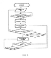
図20は、本発明によるトポロジー発見方法を示すフローチャートである。上述したように、トポロジー発見コンポーネント(TD)は、基本的にトーラスメッシュにおける、上述したルーティングの分散において使用できるノード(及びノードのポート)の存在(又は不在)を発見するために重要である。この点、TDは、カナダ国特許出願公開第2014/000652号に具体的に開示されているように、本発明の新規のネットワークを単純かつ効率的に拡張できるようにする。TDは、「Hello」プロトコル及びデータベース交換プロトコルに基づく。具体的には、全てのノード及び全てのポートにおいて「Hello」メッセージが送受信される。メッセージが「Hello」として受け取られ、管理フレームワークによって「Hello」パケット内のノードIDが検証されると、ローカルノード情報が、隣接ノードへの新たなリンクの利用可能性を示すように更新される。一群のノード情報は、各ノードにおいて隣接ノードデータベース内に維持され、データベース交換プロトコルを通じて隣接ノードと同期される。各ノードは、その隣接ノードデータベースの変化を隣接ノードに送信し、これが段階的にトポロジー全体に伝搬する。特定のタイムアウト後、隣接ノードデータベースに変化が生じた場合、経路計算のために関数呼び出しが生成される。「Hello」メッセージの交換については、トポロジーの変化を検出するために、隣接ノードから隣接ノードへの交換が規定の時間間隔で永久に継続する。 FIG. 20 is a flowchart illustrating a topology discovery method according to the present invention. As mentioned above, the topology discovery component (TD) is important for discovering the presence (or absence) of nodes (and node ports) that can be used in the routing distribution described above, essentially in the torus mesh. In this regard, TD makes it possible to simply and efficiently extend the new network of the present invention, as specifically disclosed in Canadian Patent Application Publication No. 2014/000652. TD is based on the “Hello” protocol and the database exchange protocol. Specifically, “Hello” messages are transmitted and received in all nodes and all ports. When the message is received as “Hello” and the node ID in the “Hello” packet is verified by the management framework, the local node information is updated to indicate the availability of new links to neighboring nodes . A group of node information is maintained in the adjacent node database at each node and synchronized with the adjacent node through a database exchange protocol. Each node sends changes in its neighbor node database to the neighbor node, which propagates step by step throughout the topology. If a change occurs in the neighbor node database after a certain timeout, a function call is generated for path computation. For the exchange of “Hello” messages, the exchange from adjacent node to adjacent node continues indefinitely at specified time intervals in order to detect topology changes.
図21は、本発明による、トポロジー発見のためのDB交換更新を示すフローチャートである。基本的に、この図は、全ての相互接続サーバ、入力/出力リンク及び接続性状態を含む各ノードのスイッチの完全なイメージを維持することに関与するTDコンポーネントに関する。 FIG. 21 is a flowchart showing DB exchange update for topology discovery according to the present invention. Basically, this figure relates to the TD component involved in maintaining a complete image of each node's switch, including all interconnect servers, input / output links and connectivity states.
図22は、本発明のシステムがノード/リンク障害検出をどのように発見するか、及び故障したノードを避けるルート変更処理を示すフローチャートである。リンクの障害が検出されると(602)、パススルーブロックは、障害のあるリンクに向かうトラフィックをCPU603にルート変更するようにプログラムされる。トラフィックの送信元は、障害のあるリンクを避けてトラフィックを送信するように通知される(604)。これにより、トポロジー更新イベントがトリガされる(605)。リンクの回復が検出されると(606)、パススルーブロックは、リンクの障害に起因してCPUに向かうトラフィックを再び同じリンクにルート変更する(607)ようにプログラムされる。トラフィックの送信元は、リンクの障害前と同様にトラフィックを送信するように通知される(608)。これにより、トポロジー更新イベントがトリガされる(609)。リンク切断の場合にも同様の処理が行われる。図23には、リンク/ノードの障害及び回復についての疑似コードを示す。
FIG. 22 is a flowchart showing how the system of the present invention discovers node / link failure detection and route change processing to avoid a failed node. If a link failure is detected (602), the pass-through block is programmed to reroute traffic destined for the failed link to the
本発明の1つの実施形態は、新たなノードの挿入方法である。配線相互接続にノードを挿入するには、既存のノードを遮断(リンク切断)する。トーラス配線の遮断が検出されると(602)、トラフィックルート変更APIが呼び出される(604)。リンクコストが無限大に設定されて、トポロジーが更新される(全てのスイッチノードについて最短(低コスト)経路を計算する)。これにより、パケットフローをいずれかの宛先に到達するように制御するために使用するルートが定められる。新たなノードの挿入によって隣接ノードの発見がトリガされる。管理ソフトウェアは、新たなノードIDをチェックし、設定されたデータベースと比較する。ノードが有効な場合、ソフトウェアは、トポロジー更新及びルート計算処理を開始する。管理データベースが新たなノードで更新され、ノード状態がアクティブに設定される。 One embodiment of the present invention is a method for inserting a new node. To insert a node into a wiring interconnect, the existing node is blocked (link cut). When the disconnection of the torus wiring is detected (602), the traffic route change API is called (604). The link cost is set to infinity and the topology is updated (calculates the shortest (low cost) path for all switch nodes). Thereby, the route used for controlling the packet flow to reach any destination is determined. Neighboring node discovery is triggered by the insertion of a new node. The management software checks the new node ID and compares it with the set database. If the node is valid, the software starts the topology update and route calculation process. The management database is updated with the new node and the node state is set to active.
本発明の特定の実施形態について説明したが、当業者には、以下の特許請求の範囲においてこれらの実施形態の変形及び修正を行えることが明らかであろう。 While particular embodiments of the present invention have been described, it will be apparent to those skilled in the art that variations and modifications of these embodiments may be made within the scope of the following claims.
412 トポロジー更新
414 ルーティング経路計算を開始
419 Dest=initial_dest
415 現在のノードと宛先との間の最短のダイクストラ経路を計算
416 ルート発見?
417 ネットワークトポロジーから最短経路リンクを削除
418 ルーティングテーブルを更新
420 最後の宛先ノードか?
421 Dest=next(Dest)
422 ネットワークトポロジーのリンクをリセット
412 Topology update 414 Start routing
415 Calculate shortest Dijkstra path between current node and
417 Delete shortest path link from
421 Dest = next (Dest)
422 Reset network topology link
Claims (2)
ネットワークトポロジーにおける全てのノードと、各ノードの全ての出力ポートとを発見するステップと、
前記ネットワークトポロジーにおける前記発見されたノード及び出力ポートを最短経路のルーティング計算に含めるために、前記ノード及びポートをトポロジーデータベースに含めるステップと、
前記トポロジーデータベースに含まれている前記ノード及び出力ポートに基づいて、前記ネットワークトポロジーにおける各ノードの全ての出力ポートから他の全てのノードへの前記最短経路を計算するステップと、
各ノードにおいて、前記ネットワークトポロジーにおける前記各ノードの全ての出力ポートから他の全てのノードへの最短経路を含む送信元ルーティングデータベースを生成するステップと、
前記送信元ノードにおいてパケットを受け取るステップと、
前記受け取ったパケットの各々が、その後に前記送信元ノードの前記出力ポートにおいてフリットに分割されて前記送信元ノードの前記出力ポートから前記宛先ノードまでの前記最短経路に沿って分散され、この結果、前記パケットが前記ネットワークトポロジーにおける別ルートに沿って分散されるように、前記受け取ったパケットを、前記送信元ノードの前記出力ポートにラウンドロビン方式又は重み付きラウンドロビン方式で送信するステップと、
前記宛先ノードにおいて、前記パケットを該パケットの元々の形態及び順序に従うように再構築して順序変更するステップと、
を含むことを特徴とするコンピュータ実装方法。 A computer-implemented method for routing packets from a source node to a destination node in a direct interconnect network, comprising:
Discovering all nodes in the network topology and all output ports of each node;
Including the nodes and ports in a topology database to include the discovered nodes and output ports in the network topology in a shortest path routing calculation;
Calculating the shortest path from all output ports of each node in the network topology to all other nodes based on the nodes and output ports contained in the topology database;
At each node, generating a source routing database including shortest paths from all output ports of each node in the network topology to all other nodes;
Receiving a packet at the source node;
Each of the received packets is then divided into flits at the output port of the source node and distributed along the shortest path from the output port of the source node to the destination node, resulting in: Transmitting the received packet to the output port of the source node in a round-robin manner or a weighted round-robin manner so that the packet is distributed along another route in the network topology;
Reordering and reordering the packets to follow the original form and order of the packets at the destination node;
A computer-implemented method comprising:
請求項1に記載のコンピュータ実装方法。 The flit is forwarded to the destination node using wormhole switching.
The computer-implemented method of claim 1.
Applications Claiming Priority (3)
| Application Number | Priority Date | Filing Date | Title |
|---|---|---|---|
| US201461939487P | 2014-02-13 | 2014-02-13 | |
| US61/939,487 | 2014-02-13 | ||
| PCT/CA2015/000081 WO2015120539A1 (en) | 2014-02-13 | 2015-02-13 | Method to route packets in a distributed direct interconnect network |
Publications (2)
| Publication Number | Publication Date |
|---|---|
| JP2017506049A JP2017506049A (en) | 2017-02-23 |
| JP6267367B2 true JP6267367B2 (en) | 2018-01-24 |
Family
ID=53799463
Family Applications (1)
| Application Number | Title | Priority Date | Filing Date |
|---|---|---|---|
| JP2016568984A Active JP6267367B2 (en) | 2014-02-13 | 2015-02-13 | Packet routing method in distributed direct interconnection network |
Country Status (12)
| Country | Link |
|---|---|
| US (3) | US10142219B2 (en) |
| EP (1) | EP3087708B1 (en) |
| JP (1) | JP6267367B2 (en) |
| KR (1) | KR101809396B1 (en) |
| CN (2) | CN106165356B (en) |
| AU (1) | AU2015218201B2 (en) |
| BR (1) | BR112016018294A2 (en) |
| CA (1) | CA2939402C (en) |
| DK (1) | DK3087708T3 (en) |
| IL (1) | IL246982B (en) |
| NO (1) | NO2776466T3 (en) |
| WO (1) | WO2015120539A1 (en) |
Families Citing this family (40)
| Publication number | Priority date | Publication date | Assignee | Title |
|---|---|---|---|---|
| NO2776466T3 (en) | 2014-02-13 | 2018-01-20 | ||
| WO2016159945A1 (en) * | 2015-03-28 | 2016-10-06 | Intel Corporation | Distributed routing table system with improved support for multiple network topologies |
| US10084860B2 (en) * | 2015-04-09 | 2018-09-25 | Electronics And Telecommunications Research Institute | Distributed file system using torus network and method for configuring and operating distributed file system using torus network |
| US20170171084A1 (en) * | 2015-12-09 | 2017-06-15 | Alcatel-Lucent Usa, Inc. | Valiant load balanced segment routing |
| JP2017120542A (en) * | 2015-12-28 | 2017-07-06 | 富士通株式会社 | Parallel information processor, data transmission method, and data transmission program |
| US10572537B2 (en) * | 2016-04-13 | 2020-02-25 | International Business Machines Corporation | Efficient graph optimization |
| US9954611B1 (en) * | 2016-12-16 | 2018-04-24 | Futurewei Technologies, Inc. | System and method for abstracting wavelength-switched optical network traffic engineering topology in SDN control hierarchy |
| KR102610984B1 (en) * | 2017-01-26 | 2023-12-08 | 한국전자통신연구원 | Distributed file system using torus network and method for operating of the distributed file system using torus network |
| CN109218176B (en) * | 2017-06-30 | 2020-12-15 | 华为技术有限公司 | Message processing method and device |
| US11347774B2 (en) * | 2017-08-01 | 2022-05-31 | Salesforce.Com, Inc. | High availability database through distributed store |
| CN107733802B (en) * | 2017-09-18 | 2020-11-13 | 深圳市盛路物联通讯技术有限公司 | Node control method and system of distributed network topology structure |
| CA2982147A1 (en) * | 2017-10-12 | 2019-04-12 | Rockport Networks Inc. | Direct interconnect gateway |
| US10855581B2 (en) | 2017-11-10 | 2020-12-01 | Fabriscale Technologies AS | System and method of computing ethernet routing paths |
| CN110166310B (en) * | 2018-01-30 | 2020-08-21 | 山东衡昊信息技术有限公司 | Rapid calculation method for concurrent big data transmission delay based on wormhole network |
| GB201802347D0 (en) | 2018-02-13 | 2018-03-28 | Nchain Holdings Ltd | Computer-implemented system and method |
| CN110324249B (en) * | 2018-03-28 | 2023-05-26 | 清华大学 | Dragonfly network architecture and multicast routing method thereof |
| US10944693B2 (en) * | 2018-11-13 | 2021-03-09 | Advanced Micro Devices, Inc. | Routing flits in a network-on-chip based on operating states of routers |
| JP7167687B2 (en) * | 2018-12-18 | 2022-11-09 | 富士通株式会社 | Information processing device, information processing method and information processing program |
| CN109525518B (en) * | 2018-12-25 | 2021-01-12 | 北京物芯科技有限责任公司 | IP message network address conversion method and device based on FPGA |
| CN109768924B (en) * | 2019-02-14 | 2021-06-08 | 山东省计算中心(国家超级计算济南中心) | SDN network multilink fault recovery method and system oriented to multi-stream coexistence |
| US11252034B1 (en) * | 2019-03-15 | 2022-02-15 | Juniper Networks, Inc. | Generating candidate links and candidate paths before selecting links for an optimized optical network plan |
| CN110198268A (en) * | 2019-05-15 | 2019-09-03 | 清华大学 | The high-dimensional Torus network architecture and adaptive routing method |
| US11055191B2 (en) * | 2019-05-17 | 2021-07-06 | Citrix Systems, Inc. | Service graph highlights missing nodes and links |
| CN112039795B (en) * | 2019-06-04 | 2022-08-26 | 华为技术有限公司 | Load sharing method, device and network equipment |
| CN112491672B (en) * | 2019-09-11 | 2022-05-06 | 杭州海康威视数字技术股份有限公司 | PCIE communication system, communication configuration parameter backup method and PCIE switch |
| US20210111990A1 (en) * | 2019-10-14 | 2021-04-15 | Cisco Technology, Inc. | Systems and methods for providing multiple disjointed paths to core network at first-mile access |
| US11121984B2 (en) * | 2019-10-18 | 2021-09-14 | Ciena Corporation | Routing tables for forwarding packets between switches in a data center network |
| US11775470B2 (en) * | 2019-11-20 | 2023-10-03 | Intel Corporation | Transaction layer packet format |
| US11212212B2 (en) * | 2020-04-15 | 2021-12-28 | Hewlett Packard Enterprise Development Lp | Non-isolated topologies in computing network environments |
| CN111970202B (en) * | 2020-08-28 | 2021-09-10 | 电子科技大学 | Network topology discovery method based on three-way sub-topology measurement |
| CN113347029B (en) * | 2020-09-29 | 2022-05-31 | 北京航空航天大学 | Torus network fault tolerance method based on topology reconstruction and path planning |
| RU2753147C1 (en) * | 2020-11-20 | 2021-08-12 | Федеральное государственное бюджетное учреждение науки Институт проблем управления им. В.А. Трапезникова Российской академии наук | Method for organizing optimal fault-tolerant multidimensional tori based on low-port routers and duplex channel splitters |
| US20230198860A1 (en) * | 2021-01-28 | 2023-06-22 | Rockport Networks Inc. | Systems and methods for the temporal monitoring and visualization of network health of direct interconnect networks |
| CN113037637B (en) * | 2021-03-23 | 2022-10-14 | 福建师范大学 | Method for selecting fault-tolerant information transmission path of man-machine thing fusion network |
| WO2022221466A1 (en) * | 2021-04-13 | 2022-10-20 | The Regents Of The University Of California | Configurable memory pool system |
| CA3221912A1 (en) * | 2021-06-09 | 2022-12-15 | Alan James Jennings | Method for distributing multipath flows in a direct interconnect network |
| WO2022269357A1 (en) * | 2021-06-23 | 2022-12-29 | Rockport Networks Inc. | Deadlock-free multipath routing for direct interconnect networks |
| CA3227857A1 (en) * | 2021-08-05 | 2023-02-09 | Dan Oprea | Method for signaling link or node failure in a direct interconnect network |
| CN115499271B (en) * | 2022-08-30 | 2023-10-13 | 西北工业大学 | Hybrid network topology structure and routing method thereof |
| CN117155846B (en) * | 2023-10-31 | 2024-02-06 | 苏州元脑智能科技有限公司 | Routing method, device, computer equipment and storage medium of interconnection network |
Family Cites Families (43)
| Publication number | Priority date | Publication date | Assignee | Title |
|---|---|---|---|---|
| JP2749725B2 (en) * | 1991-03-18 | 1998-05-13 | 富士通株式会社 | Communication method of parallel computer |
| US5550815A (en) * | 1994-12-30 | 1996-08-27 | Lucent Technologies Inc. | Apparatus and method for reducing data losses in a growable packet switch |
| US5898826A (en) * | 1995-11-22 | 1999-04-27 | Intel Corporation | Method and apparatus for deadlock-free routing around an unusable routing component in an N-dimensional network |
| JPH09219702A (en) * | 1996-02-14 | 1997-08-19 | Nec Corp | Method for retrieving free route of mesh configuration |
| JP3860257B2 (en) * | 1996-06-28 | 2006-12-20 | 富士通株式会社 | How to determine the channel |
| US6285679B1 (en) * | 1997-08-22 | 2001-09-04 | Avici Systems, Inc. | Methods and apparatus for event-driven routing |
| US6751746B1 (en) * | 2000-07-31 | 2004-06-15 | Cisco Technology, Inc. | Method and apparatus for uninterrupted packet transfer using replication over disjoint paths |
| US6947433B2 (en) * | 2000-09-21 | 2005-09-20 | Avici Systems, Inc. | System and method for implementing source based and egress based virtual networks in an interconnection network |
| JP2002305541A (en) * | 2001-04-04 | 2002-10-18 | Kddi Research & Development Laboratories Inc | Load balancing method in mesh net |
| CA2410137C (en) * | 2001-11-02 | 2008-04-15 | Nippon Telegraph And Telephone Corporation | Optical dynamic burst switch |
| US7457303B2 (en) * | 2003-06-06 | 2008-11-25 | International Business Machines Corporation | One-bounce network |
| US7349350B2 (en) * | 2003-09-23 | 2008-03-25 | Intel Corporation | Determining two node-disjoint paths using on-demand flooding |
| US7280755B2 (en) * | 2003-09-26 | 2007-10-09 | Minho Kang | Highly utilizable protection mechanism for WDM mesh network |
| CN100461748C (en) * | 2004-10-22 | 2009-02-11 | 华为技术有限公司 | Method for interconnecting switched network route directly |
| WO2007094520A1 (en) * | 2006-02-16 | 2007-08-23 | Nec Corporation | Node, network system, frame transfer method, and frame transfer program |
| US8031614B2 (en) * | 2006-10-06 | 2011-10-04 | International Business Machines Corporation | Method and apparatus for routing data in an inter-nodal communications lattice of a massively parallel computer system by dynamic global mapping of contended links |
| US7765385B2 (en) * | 2007-04-18 | 2010-07-27 | International Business Machines Corporation | Fault recovery on a parallel computer system with a torus network |
| US8085659B2 (en) * | 2007-08-28 | 2011-12-27 | Universidad Politecnica De Valencia | Method and switch for routing data packets in interconnection networks |
| US8160063B2 (en) * | 2008-06-09 | 2012-04-17 | Microsoft Corporation | Data center interconnect and traffic engineering |
| CN101651599B (en) * | 2008-08-12 | 2012-05-30 | 中国移动通信集团公司 | Multipath wireless routing method and device |
| US20100142448A1 (en) * | 2008-09-04 | 2010-06-10 | Ludger Schlicht | Devices for a mobile, broadband, routable internet |
| US8065433B2 (en) * | 2009-01-09 | 2011-11-22 | Microsoft Corporation | Hybrid butterfly cube architecture for modular data centers |
| JP5195933B2 (en) * | 2009-01-30 | 2013-05-15 | 富士通株式会社 | Information processing system, information processing apparatus, information processing apparatus control method, information processing apparatus control program, and computer-readable recording medium |
| US8144626B2 (en) * | 2009-06-30 | 2012-03-27 | Fujitsu Limited | Determining disjoint paths with an optimized number of regenerators |
| US8594104B2 (en) * | 2009-11-23 | 2013-11-26 | Cisco Technology, Inc. | Providing proxy mobile IP over a communication network |
| JP5630306B2 (en) * | 2011-02-10 | 2014-11-26 | 富士通株式会社 | Route generation method, relay device, and route generation program |
| EP2708000B1 (en) * | 2011-05-08 | 2020-03-25 | The J. Scott Benson Living Trust | Flexible radix switching network |
| US9736054B2 (en) * | 2011-10-05 | 2017-08-15 | Cisco Technology, Inc. | Multicast active source discovery and management for layer-2 interconnect solutions |
| US9185166B2 (en) * | 2012-02-28 | 2015-11-10 | International Business Machines Corporation | Disjoint multi-pathing for a data center network |
| USRE49275E1 (en) * | 2012-09-28 | 2022-11-01 | Cornell University | System and methods for improved network routing |
| US8989017B2 (en) * | 2012-12-14 | 2015-03-24 | Intel Corporation | Network congestion management by packet circulation |
| US9401862B2 (en) * | 2013-02-07 | 2016-07-26 | Dell Products L.P. | Optimized internet small computer system interface path |
| CN103327563A (en) * | 2013-04-25 | 2013-09-25 | 张家港中科港联物联网科技有限公司 | Multi-path unicast method based on position information in wireless self-organization and sensor network |
| US9311022B2 (en) * | 2013-10-07 | 2016-04-12 | Dell Products L.P. | System and method for improved communication in a storage network |
| NO2776466T3 (en) | 2014-02-13 | 2018-01-20 | ||
| US20160026558A1 (en) * | 2014-07-26 | 2016-01-28 | Wipro Limited | Method and system for managing virtual services to optimize operational efficiency of software testing |
| CN105871722B (en) * | 2015-01-19 | 2020-02-14 | 中兴通讯股份有限公司 | Label structure and label message forwarding method and device |
| US10116557B2 (en) * | 2015-05-22 | 2018-10-30 | Gray Research LLC | Directional two-dimensional router and interconnection network for field programmable gate arrays, and other circuits and applications of the router and network |
| US10616100B2 (en) * | 2016-11-03 | 2020-04-07 | Parallel Wireless, Inc. | Traffic shaping and end-to-end prioritization |
| US10701126B2 (en) * | 2017-08-31 | 2020-06-30 | Wipro Limited | Method and a system to deliver multimedia content in a downstream network |
| JP6946955B2 (en) * | 2017-11-10 | 2021-10-13 | 富士通株式会社 | Information processing device, arithmetic processing device, and control method of information processing device |
| US10476815B2 (en) * | 2017-12-11 | 2019-11-12 | Ciena Corporation | Adaptive communication network with cross-point switches |
| US11677628B2 (en) * | 2017-12-12 | 2023-06-13 | Lenovo Enterprise Solutions (Singapore) Pte. Ltd. | Topology discovery between compute nodes and interconnect switches |
-
2012
- 2012-11-09 NO NO12801467A patent/NO2776466T3/no unknown
-
2015
- 2015-02-13 BR BR112016018294A patent/BR112016018294A2/en active Search and Examination
- 2015-02-13 KR KR1020167024812A patent/KR101809396B1/en active IP Right Grant
- 2015-02-13 JP JP2016568984A patent/JP6267367B2/en active Active
- 2015-02-13 AU AU2015218201A patent/AU2015218201B2/en active Active
- 2015-02-13 CN CN201580019119.6A patent/CN106165356B/en active Active
- 2015-02-13 CA CA2939402A patent/CA2939402C/en active Active
- 2015-02-13 US US15/114,722 patent/US10142219B2/en active Active
- 2015-02-13 DK DK15748836.2T patent/DK3087708T3/en active
- 2015-02-13 WO PCT/CA2015/000081 patent/WO2015120539A1/en active Application Filing
- 2015-02-13 CN CN201910860198.3A patent/CN110708241B/en active Active
- 2015-02-13 EP EP15748836.2A patent/EP3087708B1/en active Active
-
2016
- 2016-07-27 IL IL246982A patent/IL246982B/en active IP Right Grant
-
2018
- 2018-10-11 US US16/157,966 patent/US10693767B2/en active Active
-
2020
- 2020-06-22 US US16/908,669 patent/US11362934B2/en active Active
Also Published As
| Publication number | Publication date |
|---|---|
| CA2939402A1 (en) | 2015-08-20 |
| US20200322258A1 (en) | 2020-10-08 |
| US20160344618A1 (en) | 2016-11-24 |
| CN110708241B (en) | 2021-10-08 |
| DK3087708T3 (en) | 2018-06-14 |
| EP3087708B1 (en) | 2018-04-11 |
| EP3087708A4 (en) | 2017-08-02 |
| WO2015120539A1 (en) | 2015-08-20 |
| EP3087708A1 (en) | 2016-11-02 |
| CN106165356B (en) | 2019-10-08 |
| CN110708241A (en) | 2020-01-17 |
| CN106165356A (en) | 2016-11-23 |
| US11362934B2 (en) | 2022-06-14 |
| US10142219B2 (en) | 2018-11-27 |
| BR112016018294A2 (en) | 2017-08-08 |
| KR101809396B1 (en) | 2017-12-14 |
| NO2776466T3 (en) | 2018-01-20 |
| WO2015120539A8 (en) | 2016-08-11 |
| US10693767B2 (en) | 2020-06-23 |
| KR20160122192A (en) | 2016-10-21 |
| JP2017506049A (en) | 2017-02-23 |
| AU2015218201A1 (en) | 2016-08-04 |
| CA2939402C (en) | 2017-10-24 |
| US20190068484A1 (en) | 2019-02-28 |
| AU2015218201B2 (en) | 2017-11-09 |
| IL246982B (en) | 2018-01-31 |
Similar Documents
| Publication | Publication Date | Title |
|---|---|---|
| JP6267367B2 (en) | Packet routing method in distributed direct interconnection network | |
| EP2777229B1 (en) | System and method for providing deadlock free routing between switches in a fat-tree topology | |
| EP3809646A1 (en) | Routing tables for forwarding packets between switches in a data center network | |
| US9825844B2 (en) | Network topology of hierarchical ring with recursive shortcuts | |
| US20180026878A1 (en) | Scalable deadlock-free deterministic minimal-path routing for dragonfly networks | |
| Wang et al. | NovaCube: A low latency Torus-based network architecture for data centers | |
| Guay et al. | vFtree-A fat-tree routing algorithm using virtual lanes to alleviate congestion | |
| CN108259387B (en) | Switching system constructed by switch and routing method thereof | |
| CN108111410B (en) | Method and device for constructing deadlock-free route in network with Cartesian topology | |
| US7307995B1 (en) | System and method for linking a plurality of network switches | |
| Bogdanski | Optimized routing for fat-tree topologies | |
| CN116915708A (en) | Method for routing data packets, processor and readable storage medium | |
| Bogdanski et al. | sFtree: a fully connected and deadlock-free switch-to-switch routing algorithm for fat-trees | |
| Adamu et al. | Review of deterministic routing algorithm for network-on-chip | |
| Alshahrani | Delay modeling in data center networks: A taxonomy and performance analysis | |
| Korösi et al. | Poincare: A hyperbolic data center architecture | |
| CN116208571A (en) | Large-scale network with high port utilization | |
| Papalkar | Latency Analysis of Bidirectional Diagonal Mesh Network on Chip by Modified Q routing | |
| Guay et al. | using Virtual Lanes to Alleviate Congestion | |
| Bogdanski et al. | Deadlock-Free Switch-to-Switch Routing Algorithm for Fat-Trees |
Legal Events
| Date | Code | Title | Description |
|---|---|---|---|
| A621 | Written request for application examination |
Free format text: JAPANESE INTERMEDIATE CODE: A621 Effective date: 20170927 |
|
| A871 | Explanation of circumstances concerning accelerated examination |
Free format text: JAPANESE INTERMEDIATE CODE: A871 Effective date: 20170927 |
|
| A975 | Report on accelerated examination |
Free format text: JAPANESE INTERMEDIATE CODE: A971005 Effective date: 20171101 |
|
| TRDD | Decision of grant or rejection written | ||
| A01 | Written decision to grant a patent or to grant a registration (utility model) |
Free format text: JAPANESE INTERMEDIATE CODE: A01 Effective date: 20171218 |
|
| R150 | Certificate of patent or registration of utility model |
Ref document number: 6267367 Country of ref document: JP Free format text: JAPANESE INTERMEDIATE CODE: R150 |
|
| R250 | Receipt of annual fees |
Free format text: JAPANESE INTERMEDIATE CODE: R250 |
|
| R250 | Receipt of annual fees |
Free format text: JAPANESE INTERMEDIATE CODE: R250 |
|
| R250 | Receipt of annual fees |
Free format text: JAPANESE INTERMEDIATE CODE: R250 |