US10693326B2 - Wireless power receiving apparatus controlling effective load resistance, and effective load resistance control method - Google Patents
Wireless power receiving apparatus controlling effective load resistance, and effective load resistance control method Download PDFInfo
- Publication number
- US10693326B2 US10693326B2 US15/986,429 US201815986429A US10693326B2 US 10693326 B2 US10693326 B2 US 10693326B2 US 201815986429 A US201815986429 A US 201815986429A US 10693326 B2 US10693326 B2 US 10693326B2
- Authority
- US
- United States
- Prior art keywords
- wireless power
- load resistance
- receiving apparatus
- power receiving
- rectifier
- Prior art date
- Legal status (The legal status is an assumption and is not a legal conclusion. Google has not performed a legal analysis and makes no representation as to the accuracy of the status listed.)
- Active, expires
Links
Images


Classifications
-
- H—ELECTRICITY
- H02—GENERATION; CONVERSION OR DISTRIBUTION OF ELECTRIC POWER
- H02J—ELECTRIC POWER NETWORKS; CIRCUIT ARRANGEMENTS OR SYSTEMS FOR SUPPLYING OR DISTRIBUTING ELECTRIC POWER; SYSTEMS FOR STORING ELECTRIC ENERGY
- H02J50/00—Circuit arrangements or systems for wireless supply or distribution of electric power
- H02J50/10—Circuit arrangements or systems for wireless supply or distribution of electric power using inductive coupling
- H02J50/12—Circuit arrangements or systems for wireless supply or distribution of electric power using inductive coupling of the resonant type
Definitions
- One or more example embodiments relate to wireless power transfer, and more particularly, to a method of maximizing a wireless power transfer efficiency without communication between a wireless power transmitting apparatus and a wireless power receiving apparatus.
- An aspect provides a method of controlling an effective load resistance of a wireless power receiving apparatus using a controller included in the wireless power receiving apparatus and maintaining an optimal wireless power transfer efficiency, despite a limited inductance of a resonator, a limited transfer distance, and a changing load, in order to wirelessly transfer power.
- a wireless power receiving apparatus including a rectifier configured to generate a rectified voltage based on a magnetic field generated in a wireless power transmitting apparatus, and a controller configured to transmit, to the rectifier, a control signal for controlling a rectified phase of the rectifier to adjust an effective load resistance of the wireless power receiving apparatus.
- the controller may identify a load voltage to be applied to a load of the wireless power receiving apparatus and a load current flowing in the load, and identify the effective load resistance based on the load voltage and the load current.
- the controller may also identify an optimal effective load resistance that allows the wireless power receiving apparatus to have a maximum efficiency, determine an optimal rectified phase at which the effective load resistance is equal to the optimal effective load resistance, and transmit, to the rectifier, the control signal for controlling the rectified phase to be the optimal rectified phase.
- the optimal effective load resistance may be determined based on a parasitic resistance of the wireless power transmitting apparatus, an inductance of a transmission resonator included in the wireless power transmitting apparatus, a parasitic resistance of the wireless power receiving apparatus, an inductance of a reception resonator included in the wireless power receiving apparatus, and a coupling coefficient between the transmission resonator and the reception resonator.
- the controller may also determine an optimal rectified voltage at which the effective load resistance is equal to the optimal effective load resistance, and determine the optimal rectified phase that allows the rectifier to output the optimal rectified voltage.
- an effective load resistance control method including identifying a rectified voltage generated in a rectifier using a magnetic field received by a wireless power receiving apparatus from a wireless power transmitting apparatus, identifying an effective load resistance of the wireless power receiving apparatus, and transmitting, to the rectifier, a control signal for controlling a rectified phase of the rectifier to adjust the effective load resistance.
- the identifying of the effective load resistance may include identifying a load voltage to be applied to a load of the wireless power receiving apparatus and a load current flowing in the load, and identifying the effective load resistance to be applied to the wireless power receiving apparatus based on the load voltage the load current.
- the transmitting of the control signal to the rectifier may include identifying an optimal effective load resistance that allows the wireless power receiving apparatus to have a maximum efficiency, determining an optimal rectified phase at which the effective load resistance is equal to the optimal effective load resistance, and transmitting, to the rectifier, the control signal for controlling the rectified phase to be the optimal rectified phase.
- the optimal effective load resistance may be determined based on a parasitic resistance of the wireless power transmitting apparatus, an inductance of a transmission resonator included in the wireless power transmitting apparatus, a parasitic resistance of the wireless power receiving apparatus, an inductance of a reception resonator included in the wireless power receiving apparatus, and a coupling coefficient between the transmission resonator and the reception resonator.
- the determining of the optimal rectified phase may include determining an optimal rectified voltage at which the effective load resistance is equal to the optimal effective load resistance, and determining the optimal rectified phase that allows the rectifier to output the optimal rectified voltage.
- FIG. 1 is a diagram illustrating an example of a wireless power transmitting apparatus and a wireless power receiving apparatus according to an example embodiment
- FIG. 2 is a flowchart illustrating an example of an effective load resistance control method according to an example embodiment
- FIG. 3 is a diagram illustrating a detailed example of a wireless power transmitting apparatus and a wireless power receiving apparatus according to an example embodiment.
- first, second, A, B, (a), (b), and the like may be used herein to describe components. Each of these terminologies is not used to define an essence, order, or sequence of a corresponding component but used merely to distinguish the corresponding component from other component(s).
- a first component may be referred to as a second component, and similarly the second component may also be referred to as the first component.
- a third component may be “connected,” “coupled,” and “joined” between the first and second components, although the first component may be directly connected, coupled or joined to the second component.
- a third component may not be present therebetween.
- expressions, for example, “between” and “immediately between” and “adjacent to” and “immediately adjacent to” may also be construed as described in the foregoing.
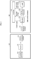
- FIG. 1 is a diagram illustrating an example of a wireless power transmitting apparatus and a wireless power receiving apparatus according to an example embodiment.
- a wireless power transmitting apparatus 101 includes an alternating current (AC)-to-direct current (DC) (AC/DC) converter 110 , an inverter 120 , and a transmission resonator 130 .
- the AC/DC converter 110 may receive an AC signal and convert the received AC signal to a DC signal.
- the inverter 120 may receive the DC signal obtained through the conversion performed by the AC/DC converter 110 , and generate a radio frequency (RF) signal for wireless power transfer using the received DC signal.
- the transmission resonator 130 may generate a magnetic field using the RF signal generated by the inverter 120 .
- a wireless power receiving apparatus 100 includes a reception resonator 140 , a rectifier 150 , a DC-to-DC (DC/DC) converter 160 , a load 170 , and a controller 180 .
- DC/DC DC-to-DC
- the reception resonator 140 may generate an AC signal using the magnetic field generated in the transmission resonator 130 of the wireless power transmitting apparatus 101 , and transmit the generated AC signal to the rectifier 150 .
- the rectifier 150 may rectify the AC signal received from the reception resonator 140 to be a DC signal using a silicon-controlled rectifier (SCR).
- the rectifier 150 may delay a phase of an SCR voltage to control a point in time at which a gate operation is turned on and adjust a magnitude of a rectified voltage.
- the phase of an SCR voltage used herein may also be referred to as a rectified phase.
- the DC/DC converter 160 may convert the rectified DC signal to a DC level required by the load 170 , and the load 170 may then consume wirelessly received power.
- the controller 180 may detect the DC signal rectified by the rectifier 150 , which is a rectified voltage, a load voltage to be applied to the load 170 , and a load current flowing in the load 170 .
- the controller 180 may identify the load 170 based on the detected load voltage and the detected load current and transmit, to the rectifier ISO, a control signal that allows an effective load resistance of the wireless power receiving apparatus 100 affected by the load 170 to be an optimal effective load resistance.
- the optimal effective load resistance may be an effective load resistance at which a maximum efficiency in wireless power transfer, or a maximum wireless power transfer efficiency, may be obtained, and the effective load resistance may be controlled by adjusting the rectified voltage.
- FIG. 2 is a flowchart illustrating an example of a method of controlling an effective load resistance according to an example embodiment.
- the method of controlling an effective load resistance may also be referred to herein as an effective load resistance control method.
- the controller 180 identifies a DC signal generated by the rectifier 150 .
- the controller 180 may detect a magnitude and a phase of a rectified voltage generated by the rectifier 150 .
- the rectified voltage detected by the controller 180 may be determined at a point in time at which a gate operation of an SCR of the rectifier 150 is turned on. That is, the rectifier 150 receiving an AC signs generated by the reception resonator 140 may generate a DC signal by rectifying the received AC signal.
- the controller 180 when generating the DC signal using the SCR of the rectifier 150 , by adjusting a phase of an SCR voltage and controlling the point in time at which the gate operation is turned on, it is possible to control the magnitude of the rectified voltage.
- the controller 180 identifies a load voltage to be applied to the load 170 and a load current flowing in the load 170 . In addition, the controller 180 determines a value of the load 170 based on the identified load voltage and the identified load current. In addition, the controller 180 identifies an effective load resistance of the wireless power receiving apparatus 100 based on the determined value of the load 170 .
- the controller 180 determines whether the effective load resistance is equal to an optimal effective load resistance needed for an optimal efficiency in wireless power transfer, or simply an optimal wireless power transfer efficiency.
- the controller 180 may determine a wireless power transfer efficiency based on a wireless power transfer frequency, an inductance and a parasitic resistance of the wireless power transmitting apparatus 101 , and an inductance, a parasitic resistance, and an effective load resistance of the wireless power receiving apparatus 100 , and a coupling coefficient between the transmission resonator 130 and the reception resonator 140 .
- the controller 180 may determine, to be the optimal effective load resistance, an effective load resistance at which the wireless power transfer efficiency becomes at its maximum.
- the controller 180 may also determine whether the effective load resistance of the wireless power receiving apparatus 100 is equal to the optimal effective load resistance.
- the controller 180 adjusts a rectified phase of the rectifier 150 .
- the effective load resistance of the wireless power receiving apparatus 100 may be determined by a load resistance and the point in time at which the gate operation of the SCR is turned on.
- the point in time at which the gate operation is turned on may be determined by the rectified phase.
- the controller 180 may determine an optimal rectified voltage at which the wireless power receiving apparatus 100 has the optimal effective load resistance, and an optimal rectified phase needed to output the optimal rectified voltage.
- the controller 180 may determine whether the rectified voltage identified in operation 200 is the optimal rectified voltage.
- the controller 180 may transmit, to the rectifier 150 , a control signal to adjust the rectified phase of the rectifier 150 to the optimal rectified phase to adjust a magnitude of the rectified voltage.
- the rectifier 150 may adjust the rectified phase based on the control signal received from the controller 180 .
- FIG. 3 is a diagram illustrating a detailed example of the wireless power transmitting apparatus 101 and the wireless power receiving apparatus 100 of FIG. 1 .
- a transmission parasitic resistance indicating all parasitic resistance components in the wireless power transmitting apparatus 101 is indicated as R tx
- an inductance of the transmission resonator 130 is indicated as L tx
- a reception parasitic resistance indicating all parasitic resistance components in the wireless power receiving apparatus 100 is indicated as R rx
- an inductance of the reception resonator 140 is indicated as L rx
- a coupling coefficient between the transmission resonator 130 and the reception resonator 140 is indicated as k.
- a size of a transmission resonator and a size a reception resonator, and a transfer distance may be determined or limited based on a magnitude of a load, power consumption, and the like, and thus an inductance of the transmission resonator and an inductance of the reception resonator may also be determined or limited accordingly.
- a wireless power transfer efficiency ⁇ may be determined based on Equation 1 under the condition of a limited inductance and a limited transfer distance.
- Equation 1 f t denotes a wireless power transfer frequency.
- the controller 180 determines an optimal effective load resistance R L_eff_opt at which the wireless power transfer efficiency ⁇ has a maximum value as represented by Equation 2 based on the transmission parasitic resistance R tx of the wireless power transmitting apparatus 101 , the inductance L tx of the transmission resonator 130 , the reception parasitic resistance R rx of the wireless power receiving apparatus 100 , the inductance L rx of the reception resonator 140 , and the coupling coefficient k between the transmission resonator 130 and the reception resonator 110 .
- R L_eff ⁇ _opt R rx ⁇ ( 1 + ( 2 ⁇ ⁇ ⁇ ⁇ f t ) 2 ⁇ k 2 ⁇ L tx ⁇ L rx R tx ⁇ R rx ) [ Equation ⁇ ⁇ 2 ]
- An effective load resistance R L_eff of the wireless power receiving apparatus 100 may be an equivalent resistance including a resistance of the DC/DC converter 160 and a resistance R L of the load 170 that actually consumes power.
- the effective load resistance R L_eff may indicate a transfer characteristic that varies depending on a type of DC/DC converter.
- the effective load resistance R L_eff may have a relationship with the resistance R L of the load 170 as represented by Equation 3.
- R L_eff ( 1 D ) 2 ⁇ R L [ Equation ⁇ ⁇ 3 ]
- Equation 3 D denotes an interval in which a switch of the DC/DC converter 160 is turned on, and has a value being between 0 and 1.
- a rectified voltage V rec and a load voltage V L may have a relationship represented by Equation 4 based on the relationship represented by Equation 3 above.
- V rec ( 1 D ) ⁇ V L [ Equation ⁇ ⁇ 4 ]
- the controller 180 may transmit, to the rectifier 150 , a control signal that satisfies Equation 5 to obtain a maximum wireless power transfer efficiency in a given circumstance although the load 170 is changed and the load resistance R L is also changed.
- the controller 180 may transmit, to the rectifier 150 , the control signal to control the rectified voltage V rec input to the DC/DC converter 160 such that the wireless power receiving apparatus 100 has a maximum wireless power transfer efficiency.
- the rectifier 150 may adjust a voltage ratio between the rectified voltage V rec and the load voltage V L by adjusting the rectified phase based on the received control signal, and thus may control the effective load resistance R L_eff to be equal to the optimal effective load resistance R L_eff_opt .
- the controller 180 may detect the load voltage V L and the load current I L of the wireless power receiving apparatus 100 on a periodic basis, and measure the load 170 based on the detected load voltage V L and the detected load current I L on a periodic basis. The controller 180 may also transmit, to the rectifier 150 , the control signal such that the identified effective load resistance becomes the optimal effective load resistance that is set in advance based on a wireless transfer environment, using the measured load 170 . In addition, the rectifier 150 may control the rectified voltage V rec by adjusting the rectified phase based on the received control signal.
- the components described in the example embodiments of the present disclosure may be achieved by hardware components including at least one of a digital signal processor (DSP), a processor, a controller, an application specific integrated circuit (ASIC), a programmable logic element such as a field programmable gate array (FPGA), other electronic devices, and combinations thereof.
- DSP digital signal processor
- ASIC application specific integrated circuit
- FPGA field programmable gate array
- At least some of the functions or the processes described in the example embodiments of the present disclosure may be achieved by software, and the software may be recorded on a recording medium.
- the components, the functions, and the processes described in the example embodiments of the present disclosure may be achieved by a combination of hardware and software.
- the processing device described herein may be implemented using hardware components, software components, and/or a combination thereof.
- the processing device and the component described herein may be implemented using one or more general-purpose or special purpose computers, such as, for example, a processor, a controller and an arithmetic logic unit (ALU), a digital signal processor, a microcomputer, a field programmable gate array (FPGA), a programmable logic unit (PLU), a microprocessor, or any other device capable of responding to and executing instructions in a defined manner.
- the processing device may run an operating system (OS) and one or more software applications that run on the OS.
- the processing device also may access, store, manipulate, process, and create data in response to execution of the software.
- OS operating system
- the processing device also may access, store, manipulate, process, and create data in response to execution of the software.
- a processing device may include multiple processing elements and/or multiple types of processing elements.
- a processing device may include multiple processors or a processor and a controller.
- different processing configurations are possible, such as parallel processors.
- the methods according to the above-described example embodiments may be recorded in non-transitory computer-readable media including program instructions to implement various operations of the above-described example embodiments.
- the media may also include, alone or in combination with the program instructions, data files, data structures, and the like.
- the program instructions recorded on the media may be those specially designed and constructed for the purposes of example embodiments, or they may be of the kind well-known and available to those having skill in the computer software arts.
- non-transitory computer-readable media examples include magnetic media such as hard disks, floppy disks, and magnetic tape; optical media such as CD-ROM discs, DVDs, and/or Blue-ray discs; magneto-optical media such as optical discs; and hardware devices that are specially configured to store and perform program instructions, such as read-only memory (ROM), random access memory (RAM), flash memory (e.g., USB flash drives, memory cards, memory sticks, etc.), and the like.
- program instructions include both machine code, such as produced by a compiler, and files containing higher level code that may be executed by the computer using an interpreter.
- the above-described devices may be configured to act as one or more software modules in order to perform the operations of the above-described example embodiments, or vice versa.
Landscapes
- Engineering & Computer Science (AREA)
- Computer Networks & Wireless Communication (AREA)
- Power Engineering (AREA)
- Charge And Discharge Circuits For Batteries Or The Like (AREA)
Abstract
Description
Claims (10)
Applications Claiming Priority (4)
| Application Number | Priority Date | Filing Date | Title |
|---|---|---|---|
| KR20170095484 | 2017-07-27 | ||
| KR10-2017-0095484 | 2017-07-27 | ||
| KR1020170133795A KR102154223B1 (en) | 2017-07-27 | 2017-10-16 | Wireless power receiving device capable of controlling effective load resistance and effective load resistance control method |
| KR10-2017-0133795 | 2017-10-16 |
Publications (2)
| Publication Number | Publication Date |
|---|---|
| US20190036379A1 US20190036379A1 (en) | 2019-01-31 |
| US10693326B2 true US10693326B2 (en) | 2020-06-23 |
Family
ID=65038270
Family Applications (1)
| Application Number | Title | Priority Date | Filing Date |
|---|---|---|---|
| US15/986,429 Active 2038-09-08 US10693326B2 (en) | 2017-07-27 | 2018-05-22 | Wireless power receiving apparatus controlling effective load resistance, and effective load resistance control method |
Country Status (1)
| Country | Link |
|---|---|
| US (1) | US10693326B2 (en) |
Citations (11)
| Publication number | Priority date | Publication date | Assignee | Title |
|---|---|---|---|---|
| US20120153739A1 (en) * | 2010-12-21 | 2012-06-21 | Cooper Emily B | Range adaptation mechanism for wireless power transfer |
| KR101390954B1 (en) | 2012-12-18 | 2014-04-29 | 한국과학기술원 | Wireless power receiving apparatus with automatic load resistance modulation for efficiency and power improvement |
| US20150349538A1 (en) * | 2014-05-30 | 2015-12-03 | Infineon Technologies Austria Ag | Active rectifier for efficient wireless power transfer |
| KR101617346B1 (en) | 2015-11-13 | 2016-05-02 | 대농산업전기(주) | Uninterruptible power supply and method for controlling thereof |
| US20160156200A1 (en) | 2014-11-27 | 2016-06-02 | Electronics And Telecommunications Research Institute | Wireless power receiving apparatus and power control method thereof, and wireless power system |
| US20160254691A1 (en) | 2015-02-27 | 2016-09-01 | Electronics And Telecommunications Research Institute | Wireless charging system and method of controlling permission for charging in wireless charging system |
| US20160254679A1 (en) * | 2015-02-26 | 2016-09-01 | Richtek Technology Corporation | Resonant wireless power receiver circuit and control method thereof |
| US20170149285A1 (en) | 2014-05-14 | 2017-05-25 | WQC, Inc. | Wireless power transfer system |
| KR101743071B1 (en) | 2014-11-18 | 2017-06-02 | 엘지전자 주식회사 | Wireless power transmitter,wireless power receiver, and wireless charging system |
| US20170237302A1 (en) * | 2014-11-07 | 2017-08-17 | Murata Manufacturing Co., Ltd. | Variable-distance wireless-power-transfer system with fixed tuning and power limiting |
| US20170353053A1 (en) * | 2016-06-07 | 2017-12-07 | Media Tek Inc. | Monotonic wireless power transfer |
-
2018
- 2018-05-22 US US15/986,429 patent/US10693326B2/en active Active
Patent Citations (11)
| Publication number | Priority date | Publication date | Assignee | Title |
|---|---|---|---|---|
| US20120153739A1 (en) * | 2010-12-21 | 2012-06-21 | Cooper Emily B | Range adaptation mechanism for wireless power transfer |
| KR101390954B1 (en) | 2012-12-18 | 2014-04-29 | 한국과학기술원 | Wireless power receiving apparatus with automatic load resistance modulation for efficiency and power improvement |
| US20170149285A1 (en) | 2014-05-14 | 2017-05-25 | WQC, Inc. | Wireless power transfer system |
| US20150349538A1 (en) * | 2014-05-30 | 2015-12-03 | Infineon Technologies Austria Ag | Active rectifier for efficient wireless power transfer |
| US20170237302A1 (en) * | 2014-11-07 | 2017-08-17 | Murata Manufacturing Co., Ltd. | Variable-distance wireless-power-transfer system with fixed tuning and power limiting |
| KR101743071B1 (en) | 2014-11-18 | 2017-06-02 | 엘지전자 주식회사 | Wireless power transmitter,wireless power receiver, and wireless charging system |
| US20160156200A1 (en) | 2014-11-27 | 2016-06-02 | Electronics And Telecommunications Research Institute | Wireless power receiving apparatus and power control method thereof, and wireless power system |
| US20160254679A1 (en) * | 2015-02-26 | 2016-09-01 | Richtek Technology Corporation | Resonant wireless power receiver circuit and control method thereof |
| US20160254691A1 (en) | 2015-02-27 | 2016-09-01 | Electronics And Telecommunications Research Institute | Wireless charging system and method of controlling permission for charging in wireless charging system |
| KR101617346B1 (en) | 2015-11-13 | 2016-05-02 | 대농산업전기(주) | Uninterruptible power supply and method for controlling thereof |
| US20170353053A1 (en) * | 2016-06-07 | 2017-12-07 | Media Tek Inc. | Monotonic wireless power transfer |
Non-Patent Citations (1)
| Title |
|---|
| W. X. Zhong et al., IEEE Transactions on Power Electronics, "Maximum Energy Efficiency Tracking for Wireless Power Transfer Systems", Aug. 28, 2014, pp. 4025-4034, vol. 30, No. 7, Jul. 2015, IEEE. |
Also Published As
| Publication number | Publication date |
|---|---|
| US20190036379A1 (en) | 2019-01-31 |
Similar Documents
| Publication | Publication Date | Title |
|---|---|---|
| US20240006927A1 (en) | Method and apparatus for controlling wireless power transmission | |
| US11025101B2 (en) | Wireless power transmitter and control method thereof | |
| EP2985865B1 (en) | Wireless power transmission device | |
| US12470091B2 (en) | Power transmission apparatus, power receiving apparatus, control methods thereof, and storage medium | |
| US10116169B2 (en) | Wireless power transmitter and method for controlling resonance frequency using the same | |
| US20180205265A1 (en) | Wireless power transmitter | |
| US10135289B2 (en) | Wireless power receiver and method for controlling the wireless power receiver | |
| US10063065B2 (en) | Wireless power transmitter | |
| US10505384B2 (en) | Wireless charging apparatus and method | |
| US9502975B2 (en) | Switch control circuit, switch control method and converter using the same | |
| KR101767276B1 (en) | Battery charging method and system using wireless power transmission | |
| US20230198315A1 (en) | Power transmission apparatus, power reception apparatus, control method, and computer-readable storage medium | |
| US20170126065A1 (en) | Wireless power transmission apparatus and method of controlling the same | |
| CN106253359A (en) | Wireless power dispensing device and control method thereof | |
| US9768647B2 (en) | Wireless power receiver and method for controlling the same | |
| US20260005551A1 (en) | Power transmitting apparatus, power receiving apparatus, control method, and storage medium | |
| US9923604B2 (en) | Power transmitting apparatus, power transmitting method, and storage medium | |
| KR102512678B1 (en) | Electronic device for wirelessly receiving power and method for operating thereof | |
| US20210296941A1 (en) | Power receiving apparatus, control method of power receiving apparatus and storage medium | |
| US10693326B2 (en) | Wireless power receiving apparatus controlling effective load resistance, and effective load resistance control method | |
| WO2014208056A2 (en) | Wireless power transmission/reception apparatus | |
| US20170012540A1 (en) | Power supply apparatus and method for controlling converter | |
| KR102483258B1 (en) | Wireless power transmission apparatus and wireless power transmission method thereof | |
| WO2025117450A1 (en) | Efficiency reporting in wireless charging systems | |
| JP2017208941A (en) | Wireless transmission apparatus, control circuit, charger, and malfunction detection method therefor |
Legal Events
| Date | Code | Title | Description |
|---|---|---|---|
| AS | Assignment |
Owner name: ELECTRONICS AND TELECOMMUNICATIONS RESEARCH INSTIT Free format text: ASSIGNMENT OF ASSIGNORS INTEREST;ASSIGNORS:KIM, SEONG-MIN;KIM, SANG-WON;MOON, JUNG ICK;AND OTHERS;REEL/FRAME:045875/0230 Effective date: 20180404 Owner name: ELECTRONICS AND TELECOMMUNICATIONS RESEARCH INSTITUTE, KOREA, REPUBLIC OF Free format text: ASSIGNMENT OF ASSIGNORS INTEREST;ASSIGNORS:KIM, SEONG-MIN;KIM, SANG-WON;MOON, JUNG ICK;AND OTHERS;REEL/FRAME:045875/0230 Effective date: 20180404 |
|
| FEPP | Fee payment procedure |
Free format text: ENTITY STATUS SET TO UNDISCOUNTED (ORIGINAL EVENT CODE: BIG.); ENTITY STATUS OF PATENT OWNER: SMALL ENTITY |
|
| FEPP | Fee payment procedure |
Free format text: ENTITY STATUS SET TO SMALL (ORIGINAL EVENT CODE: SMAL); ENTITY STATUS OF PATENT OWNER: SMALL ENTITY |
|
| STPP | Information on status: patent application and granting procedure in general |
Free format text: DOCKETED NEW CASE - READY FOR EXAMINATION |
|
| STPP | Information on status: patent application and granting procedure in general |
Free format text: NON FINAL ACTION MAILED |
|
| STPP | Information on status: patent application and granting procedure in general |
Free format text: NOTICE OF ALLOWANCE MAILED -- APPLICATION RECEIVED IN OFFICE OF PUBLICATIONS |
|
| STPP | Information on status: patent application and granting procedure in general |
Free format text: PUBLICATIONS -- ISSUE FEE PAYMENT VERIFIED |
|
| STCF | Information on status: patent grant |
Free format text: PATENTED CASE |
|
| MAFP | Maintenance fee payment |
Free format text: PAYMENT OF MAINTENANCE FEE, 4TH YR, SMALL ENTITY (ORIGINAL EVENT CODE: M2551); ENTITY STATUS OF PATENT OWNER: SMALL ENTITY Year of fee payment: 4 |