US10693319B2 - Wireless charging pad including plurality of small power transmission coils and device for and method of driving wireless charging pad in wireless power transmission system - Google Patents
Wireless charging pad including plurality of small power transmission coils and device for and method of driving wireless charging pad in wireless power transmission system Download PDFInfo
- Publication number
- US10693319B2 US10693319B2 US15/902,543 US201815902543A US10693319B2 US 10693319 B2 US10693319 B2 US 10693319B2 US 201815902543 A US201815902543 A US 201815902543A US 10693319 B2 US10693319 B2 US 10693319B2
- Authority
- US
- United States
- Prior art keywords
- power transmission
- transmission coils
- wireless charging
- driving
- coils
- Prior art date
- Legal status (The legal status is an assumption and is not a legal conclusion. Google has not performed a legal analysis and makes no representation as to the accuracy of the status listed.)
- Active, expires
Links
Images


Classifications
-
- H—ELECTRICITY
- H02—GENERATION; CONVERSION OR DISTRIBUTION OF ELECTRIC POWER
- H02J—ELECTRIC POWER NETWORKS; CIRCUIT ARRANGEMENTS OR SYSTEMS FOR SUPPLYING OR DISTRIBUTING ELECTRIC POWER; SYSTEMS FOR STORING ELECTRIC ENERGY
- H02J50/00—Circuit arrangements or systems for wireless supply or distribution of electric power
- H02J50/40—Circuit arrangements or systems for wireless supply or distribution of electric power using two or more transmitting or receiving devices
- H02J50/402—Circuit arrangements or systems for wireless supply or distribution of electric power using two or more transmitting or receiving devices the two or more transmitting or the two or more receiving devices being integrated in the same unit, e.g. power mats with several coils or antennas with several sub-antennas
-
- H—ELECTRICITY
- H02—GENERATION; CONVERSION OR DISTRIBUTION OF ELECTRIC POWER
- H02J—ELECTRIC POWER NETWORKS; CIRCUIT ARRANGEMENTS OR SYSTEMS FOR SUPPLYING OR DISTRIBUTING ELECTRIC POWER; SYSTEMS FOR STORING ELECTRIC ENERGY
- H02J50/00—Circuit arrangements or systems for wireless supply or distribution of electric power
- H02J50/005—Mechanical details of housing or structure aiming to accommodate the power transfer means, e.g. mechanical integration of coils, antennas or transducers into emitting or receiving devices
-
- H—ELECTRICITY
- H02—GENERATION; CONVERSION OR DISTRIBUTION OF ELECTRIC POWER
- H02J—ELECTRIC POWER NETWORKS; CIRCUIT ARRANGEMENTS OR SYSTEMS FOR SUPPLYING OR DISTRIBUTING ELECTRIC POWER; SYSTEMS FOR STORING ELECTRIC ENERGY
- H02J50/00—Circuit arrangements or systems for wireless supply or distribution of electric power
- H02J50/10—Circuit arrangements or systems for wireless supply or distribution of electric power using inductive coupling
- H02J50/12—Circuit arrangements or systems for wireless supply or distribution of electric power using inductive coupling of the resonant type
-
- H—ELECTRICITY
- H02—GENERATION; CONVERSION OR DISTRIBUTION OF ELECTRIC POWER
- H02J—ELECTRIC POWER NETWORKS; CIRCUIT ARRANGEMENTS OR SYSTEMS FOR SUPPLYING OR DISTRIBUTING ELECTRIC POWER; SYSTEMS FOR STORING ELECTRIC ENERGY
- H02J50/00—Circuit arrangements or systems for wireless supply or distribution of electric power
- H02J50/20—Circuit arrangements or systems for wireless supply or distribution of electric power using microwaves or radio frequency waves
-
- H—ELECTRICITY
- H02—GENERATION; CONVERSION OR DISTRIBUTION OF ELECTRIC POWER
- H02J—ELECTRIC POWER NETWORKS; CIRCUIT ARRANGEMENTS OR SYSTEMS FOR SUPPLYING OR DISTRIBUTING ELECTRIC POWER; SYSTEMS FOR STORING ELECTRIC ENERGY
- H02J50/00—Circuit arrangements or systems for wireless supply or distribution of electric power
- H02J50/80—Circuit arrangements or systems for wireless supply or distribution of electric power involving the exchange of data, concerning supply or distribution of electric power, between transmitting devices and receiving devices
-
- H—ELECTRICITY
- H02—GENERATION; CONVERSION OR DISTRIBUTION OF ELECTRIC POWER
- H02J—ELECTRIC POWER NETWORKS; CIRCUIT ARRANGEMENTS OR SYSTEMS FOR SUPPLYING OR DISTRIBUTING ELECTRIC POWER; SYSTEMS FOR STORING ELECTRIC ENERGY
- H02J50/00—Circuit arrangements or systems for wireless supply or distribution of electric power
- H02J50/90—Circuit arrangements or systems for wireless supply or distribution of electric power involving detection or optimisation of position, e.g. alignment
-
- H02J7/025—
-
- H04B5/0037—
-
- H04B5/0087—
-
- H—ELECTRICITY
- H04—ELECTRIC COMMUNICATION TECHNIQUE
- H04B—TRANSMISSION
- H04B5/00—Near-field transmission systems, e.g. inductive or capacitive transmission systems
- H04B5/20—Near-field transmission systems, e.g. inductive or capacitive transmission systems characterised by the transmission technique; characterised by the transmission medium
- H04B5/24—Inductive coupling
- H04B5/26—Inductive coupling using coils
- H04B5/263—Multiple coils at either side
-
- H—ELECTRICITY
- H04—ELECTRIC COMMUNICATION TECHNIQUE
- H04B—TRANSMISSION
- H04B5/00—Near-field transmission systems, e.g. inductive or capacitive transmission systems
- H04B5/70—Near-field transmission systems, e.g. inductive or capacitive transmission systems specially adapted for specific purposes
- H04B5/79—Near-field transmission systems, e.g. inductive or capacitive transmission systems specially adapted for specific purposes for data transfer in combination with power transfer
Definitions
- the present disclosure relates to a wireless power transmission system, and more particularly to a wireless charging pad including a plurality of small power transmission coils and a device for and a method of driving the wireless charging pad in a wireless power transmission system.
- wireless power transmission is widely spreading to mobile IoT, etc., starting with the charging of portable terminals, and becoming popularized, and consumer demand therefor is gradually increasing.
- Such wireless power transmission is a technique for supplying power between a transmitter and a receiver without using a wire, and is generally classified into three types of microwave, magnetic induction, and magnetic field resonance methods.
- the microwave method using an electromagnetic radiation antenna has an advantage for a long-distance power transmission, but it exhibits a radio wave spreading phenomenon. Accordingly, the microwave method exhibits very low efficiency over a certain distance and, at high power, an area near a transmitter may harmfully affect the human body.
- the magnetic induction method as a contact-type wireless power transmission method which is currently used in wireless chargers, is advantageous in that power transmission efficiency is high over a very short distance of several millimeters and is harmless to the human body due to use of a magnetic field.
- the magnetic induction method is disadvantageous in that mobility of mobile devices is not guaranteed and efficiency is reduced even when the mobile devices are moved even by a small distance.
- a wireless power transmission system adopting magnetic field resonance has been actively studied since Marin Solajacic's MIT team first proposed the same in 2007.
- This system uses a resonance phenomenon during transmission and reception, and is advantageous in that medium-distance transmission is possible.
- the system uses a magnetic field as in the magnetic induction method, thus being harmless to the human body.
- wireless charging apparatuses have a small pad shape, such as a smart phone, configured to charge one or two devices, or are provided as a space for charging on a certain portion of a table.
- wireless charging apparatuses have a size similar to a total area of coils that are configured to wirelessly transmit power, power loss may be reduced, but mobility may be limited.
- Korean Patent Publication Application No. 2012-0117262 (entitled “WIRELESS POWER TRANSMISSION DEVICE FOR VEHICLES CONFIGURED TO ALLOW POSITION ALIGNMENT OF COILS), as a related technology to the present disclosure, discloses a charging manner characterized by disposing a plurality of coils in a charging pad.
- a wireless power transmission device does not have a configuration capable of efficiently controlling driving of coils.
- a manner of moving coils per se is disadvantageous in that an additional device, such as a motor, is required.
- the present disclosure has been made in view of the above problems, and it is one object of the present disclosure to provide a wireless power transmission system being capable of applied to complex wireless channel environments such as homes, offices, airports, and trains.
- a wireless charging apparatus including a plurality of small power transmission coils
- the wireless charging apparatus includes a driving controller configured to generate a first control signal so as to apply a first driving voltage having a first phase to power transmission coils to be driven matching a device to be charged among the small power transmission coils and generate a second control signal so as to apply a second driving voltage having a phase different from the first phase to power transmission coils surrounding the power transmission coils to be driven; and a coil driver configured to apply the first and second driving signals to a wireless charging pad.
- a driving device for a wireless charging pad including a plurality of small power transmission coils, the driving device including a first driving controller configured to each independently control driving of small power transmission coils of a first wireless charge module including the small power transmission coils; a second driving controller configured to each independently control driving of small power transmission coils of a second wireless charge module including the small power transmission coils; and a plurality of driving modules configured to respectively drive the small power transmission coils of the first and second wireless charge modules according to a first or second control signal input from the first and second driving controllers.
- a method of driving a wireless charging pad including a plurality of small power transmission coils including a plurality of small power transmission coils, the method including a coil driving determination step of investigating power transmission coils to be driven matching a device to be charged among the small power transmission coils and investigating power transmission coils surrounding the power transmission coils to be driven among the small power transmission coils; a control signal generation step of generating a first control signal to apply a first driving voltage having a first phase to the power transmission coils to be driven and generating a second control signal to apply a second driving voltage having a phase opposite to the first phase to the surrounding power transmission coils; and a driving signal application step of applying the first and second control signals to a wireless charging pad.
- FIG. 1 is a drawing illustrating a configuration of a wireless charging apparatus including a wireless charging pad constituted of a plurality of small power transmission coils according to an embodiment of the present disclosure
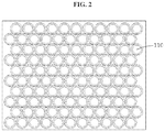
- FIG. 2 is a drawing illustrating arrangement of power transmission coils on the wireless charging pad illustrated in FIG. 1 ;
- FIG. 3 is a drawing illustrating a constitution of a small power transmission coil according to an embodiment of the present disclosure
- FIG. 4 is a drawing illustrating an embodiment of a device to be charged which is placed on the wireless charging pad illustrated in FIG. 1 ;
- FIG. 5 is a drawing illustrating a constitution of a driving device of the wireless charging pad illustrated in FIG. 1 ;
- FIGS. 6 and 7 are drawings illustrating operation embodiments of the wireless charging pad when a device to be charged is placed on the wireless charging pad illustrated in FIG. 1 ;
- FIG. 8 is a drawing illustrating another operation embodiment of the wireless charging pad when a device to be charged is placed on the wireless charging pad illustrated in FIG. 1 ;
- FIG. 9 is a drawing illustrating a configuration example of a driving controller and a coil driver illustrated in FIG. 5 ;
- FIG. 10 is a drawing illustrating a configuration example of a coil driver and a connection relationship between a small power transmission coil and the coil driver according to an embodiment of the present disclosure
- FIG. 11 illustrates exemplary drawings representing a phase relationship of signals A and B in FIGS. 9 and 10 ;
- FIG. 12 illustrates exemplary drawings representing a scanning method of a wireless charging pad according to an embodiment of the present disclosure
- FIG. 13 is a drawing illustrating an operation example when a plurality of devices is placed on the wireless charging pad illustrated in FIG. 1 ;
- FIG. 14 is a drawing illustrating an embodiment of a modular wireless charging pad according to an embodiment of the present disclosure.
- FIG. 15 is an exemplary drawing illustrating an environment to which a wireless power transmission system according to an embodiment of the present disclosure is applied;
- FIG. 16 is a drawing illustrating a wireless power transmission apparatus capable of transmitting power in various ways in the environment similar to that illustrated in FIG. 15 ;
- FIG. 17 is a drawing illustrating a configuration example of a near-field power transmitter illustrated in FIG. 16 ;
- FIG. 18 is a drawing illustrating an embodiment of a phase shifter illustrated in FIG. 17 ;
- FIG. 19 is a drawing illustrating a configuration and operation environment of a microwave power transmitter illustrated in FIG. 16 .
- first and second are used herein merely to describe a variety of constituent elements, but the constituent elements are not limited by the terms. The terms are used only for the purpose of distinguishing one constituent element from another constituent element.
- a wireless charging apparatus is characterized in that several small power transmission coils are disposed in a tessellation structure on a charging pad, and thus, driving of the wireless charging apparatus is controlled such that, when one or more devices to be charged are placed on the charging pad, only coils under the devices are driven and the other coils are not driven, thereby preventing power dissipation and waste.
- a separate setting element such as a shift register, is used to control respective coils, thereby effectively controlling driving of the wireless charging apparatus.
- FIG. 1 is a drawing illustrating a configuration of a wireless charging apparatus including a wireless charging pad constituted of a plurality of small power transmission coils according to an embodiment of the present disclosure.
- a wireless charging apparatus 100 includes a wireless charging pad 110 and a device 120 for driving a wireless charging pad.
- the wireless charging apparatus 100 may be referred to as “a wireless charging apparatus constituted of a plurality of small power transmission coils” in the specification.
- the wireless charging pad 110 may include a plurality of small power transmission coils. Each of the small power transmission coils may be constructed as illustrated in FIG. 3 .
- the small power transmission coils may be disposed in a tessellation structure, without overlapping each other, on the wireless charging pad 110 . Accordingly, a maximum number of small power transmission coils may be disposed in a limited space.
- the device 120 for driving a wireless charging pad may be implemented as an electronic circuit provided inside the wireless charging pad 110 .
- the small power transmission coils may be each independently driven.
- FIG. 2 is a drawing illustrating arrangement of power transmission coils on the wireless charging pad illustrated in FIG. 1 .
- the wireless charging pad 110 has a shape wherein the small power transmission coils are disposed in a tessellation structure thereon as described above, when viewed from above.
- charging efficiency may be constantly maintained regardless of a position of the device.
- FIG. 3 is a drawing illustrating a constitution of a small power transmission coil according to an embodiment of the present disclosure.
- each of the small power transmission coils may be constituted of a circularly wound helical coil 301 and a ferrite core 302 located inside the helical coil 301 .
- the helical coil 301 may be small in size.
- the helical coil 301 may have a radius of 3 to 10 mm and a height of 10 to 20 mm.
- FIG. 4 is a drawing illustrating an embodiment of a device to be charged which is placed on the wireless charging pad illustrated in FIG. 1 .
- DEVICE as an example of a device to be charged, i.e., is placed on the wireless charging pad 110 .
- FIG. 5 is a drawing illustrating a constitution of a driving device of the wireless charging pad illustrated in FIG. 1 .
- FIGS. 6 and 7 are drawings illustrating operation embodiments of the wireless charging pad when a device to be charged is placed on the wireless charging pad illustrated in FIG. 1 .
- FIG. 8 is a drawing illustrating another operation embodiment of the wireless charging pad when a device to be charged is placed on the wireless charging pad illustrated in FIG. 1 .
- the device 120 for driving a wireless charging pad includes a driving controller 530 and a coil driver 540 .
- the device 120 for driving a wireless charging pad may further include a coil determiner 520 and a scanning controller 510 .
- the device 120 for driving a wireless charging pad may include the driving controller 530 configured to each independently control driving of the small power transmission coils constituting the wireless charging pad; and a plurality of driving modules configured to respectively drive the small power transmission coils according to a first or second control signal input from the driving controller 530 .
- the driving controller 530 configured to each independently control driving of the small power transmission coils constituting the wireless charging pad
- a plurality of driving modules configured to respectively drive the small power transmission coils according to a first or second control signal input from the driving controller 530 .
- the scanning controller 510 scans the wireless charging pad so as to detect a device to be charged on the wireless charging pad constituted of the small power transmission coils.
- the scanning controller 510 may detect whether a device to be charged is placed on corresponding small power transmission coils, using at least one of impedance change and pressure change in each of the small power transmission coils.
- a device to be charged may be determined to be placed on corresponding coils when impedance change in the coils is out of a preset range.
- the pressure sensors may detect whether a device to be charged is placed on the pressure sensors, through pressure change.
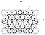
- the scanning controller 510 may detect whether a device to be charged is placed on coils 10 , 11 , 12 , 13 , 17 , 18 , 19 , 20 , 21 , 25 , 26 , 27 , and 28 by scanning the wireless charging pad.
- the coil determiner 520 investigates power transmission coils to be driven, which are located under the device to be charged, among the small power transmission coils, and investigates neighboring power transmission coils, which surround the power transmission coils to be driven, among the small power transmission coils.
- the coil determiner 520 may investigate that each of the coils 10 , 11 , 12 , 13 , 17 , 18 , 19 , 20 , 21 , 25 , 26 , 27 , and 28 is a power transmission coil to be driven.
- the coil determiner 520 may investigate coils 2 , 3 , 4 , 5 , 6 , 9 , 14 , 16 , 22 , 24 , 29 , 32 , 33 , 34 , 35 , and 36 , among the small power transmission coils, as coils surrounding the power transmission coils to be driven 10 , 11 , 12 , 13 , 17 , 18 , 19 , 20 , 21 , 25 , 26 , 27 , and 28 .
- the driving controller 530 may generate a first control signal to apply a first driving voltage having a first phase to the power transmission coils to be driven, and may generate a second control signal to apply a second driving voltage, which has a phase different from the first phase, to the surrounding power transmission coils.
- the power transmission coils to be driven may be small power transmission coils matched to a device to be charged.
- the expression “matched to a device to be charged” may refer to being located under a device to be charged, or near the device to be charged to transmit power thereto.
- clockwise arrows indicate a first phase
- counterclockwise arrows indicate a second phase
- a first control signal may be a “select” signal controlling the coil driver 540 to select a signal “A” from among a signal “A” and a signal “B” having an opposite phase to the signal “A” in FIGS. 9 and 10 .
- a second control signal may be a “select” signal controlling the coil driver 540 to select a signal “B” from among a signal “A” and a signal “B” having an opposite phase to the signal “A” in FIGS. 9 and 10 .
- the coil driver 540 applies first and second driving signals to the wireless charging pad.
- the coil driver 540 may output the first driving signal to corresponding small power transmission coils upon receiving a first control signal, and may output the second driving signal to corresponding small power transmission coils upon receiving a second control signal.
- the coil driver 540 may output the first driving signal to each of power transmission coils to be driven 10 , 11 , 12 , 13 , 17 , 18 , 19 , 20 , 21 , 25 , 26 , 27 , and 28 , and may output the second driving signal to each of surrounding power transmission coils 2 , 3 , 4 , 5 , 6 , 9 , 14 , 16 , 22 , 24 , 29 , 32 , 33 , 34 , 35 , and 36 .
- a device to be charged may be placed on a portion, which includes an edge 801 , of the wireless charging pad.
- each of coils 1 to 7 , 8 , 16 , 23 , 31 , and 38 to 44 may have index information indicating that the coils are located at an edge of the wireless charging pad, and the coil determiner 520 may determine whether corresponding coils are located at an edge of the wireless charging pad through the index information.
- coils 16 to 19 , 23 to 27 , and 31 to 34 may be determined as power transmission coils to be driven, as in the embodiment described with reference to FIGS. 6 and 7 .
- coils 16 , 23 , and 31 are determined as power transmission coils to be driven, it may be impossible to effectively reduce spreading of magnetic force to the outside.
- the coil determiner 520 may determine the small power transmission coils, which are located at the edge of the wireless charging pad, as surrounding power transmission coils.
- the coil determiner 520 may determine only coils 17 to 19 , 24 to 27 , and 32 to 34 as power transmission coils to be driven, and may determine coils 9 to 12 , 16 , 20 , 23 , 28 , 31 , 35 , and 39 to 42 as surrounding power transmission coils.
- FIG. 9 is a drawing illustrating a configuration example of a driving controller and a coil driver illustrated in FIG. 5 .
- FIG. 9 illustrates an embodiment wherein one driving controller (a first driving controller 931 ) controls four driving modules 942 , 943 , 945 , and 947 .
- a plurality of driving controllers such as second and third driving controllers, other than the first driving controller 931 may be provided.
- the first driving controller 931 may be a shift register having eight output signal terminals 901 to 908 .
- first driving controllers 931 as shift registers, are connected in a cascade form, circuits for individually driving small power transmission coils may be linearly extended.
- the driving modules 942 , 943 , 945 , and 947 may be respectively connected to the small power transmission coils.
- the first driving module 942 may be connected to a first small power transmission coil
- the second driving module 943 may be connected to a second small power transmission coil
- the third driving module 945 may be connected to a third small power transmission coil
- the fourth driving module 947 may be connected to a fourth small power transmission coil.
- the wireless charging pad when the wireless charging pad is provided with 36 small power transmission coils, the wireless charging pad may include 36 driving modules and 9 driving controllers.
- a driving device for the wireless charging pad may include a first driving controller configured to each independently control driving of small power transmission coils constituting a first wireless charging module; and a second driving controller configured to each independently control driving of a plurality of small power transmission coils constituting a second wireless charging module.
- an end of the second driving controller may be connected to the first driving controller, and another end of the second driving controller may be connected to a third driving controller, thereby supporting expansion of the wireless charge modules.
- simple module expansion may be accomplished by additionally providing a driving controller and a driver that are connected to each of the modules 1410 , 1420 , 1430 , 1440 , and 1450 .
- the coil driver includes the driving modules 942 , 943 , 945 , and 947 respectively connected to the small power transmission coils.
- the coil driver may include two bus lines that respectively apply a first switching signal A having the first phase and a second switching signal B having the second phase to the driving modules 942 , 943 , 945 , and 947 .
- FIG. 11 is an exemplary drawing to describe a phase relationship between the first and second switching signals A and B of FIGS. 9 and 10 .
- phases of signals A and B may be, for example, opposite to each other.
- the first driving controller 931 applies an enable signal and a first or second control signal, which control such that a corresponding driving module operates, to each of the driving modules.
- the first driving controller 931 may apply an enable signal to driving modules respectively connected to the power transmission coils to be driven and the surrounding power transmission coils, and may apply the first or second control signal to the driving modules to which the enable signal is applied.
- the enable signal may be output to a terminal 901
- the first control signal may be output to a terminal 902 .
- the enable signal may be output to a terminal 907
- the second control signal may be output to a terminal 908 .
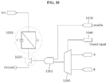
- FIG. 10 is a drawing illustrating a configuration example of a coil driver and a connection relationship between a small power transmission coil and the coil driver according to an embodiment of the present disclosure.
- reference numeral 1010 denotes an equivalent circuit of one small power transmission coil.
- One end of the small power transmission coil 1010 may be connected to a driving voltage Vcc, and another end thereof may be connected to a switching element 1020 provided in the coil driver.
- the coil driver may include the switching element 1020 connected to the small power transmission coil 1010 ; a multiplexer 1050 ; and an AND gate element 1060 .
- the coil driver may receive an enable signal through a terminal 1030 and may receive a control signal through a terminal 1040 .
- the multiplexer 1050 may output the first switching signal A when a control signal, which is input through the terminal 1040 , is a first control signal, and may output the second switching signal B when a control signal, which is input through the terminal 1040 , is a second control signal.
- the AND gate element 1060 may receive the enable signal, which is input through the terminal 1030 , and an output signal of the multiplexer 1050 to control the switching element 1020 .
- the first control signal may be input to the terminal 1040 , and the switching element 1020 may be turned on/off by a switching signal such as signal A illustrated in FIG. 11 .
- the driving voltage Vcc is applied to the small power transmission coil 1010 according to on/off of the switching element 1020 , so that the small power transmission coil 1010 operates as a first driving voltage having a first phase.
- a capacitor of the small power transmission coil 1010 is charged in a time period in which the NMOS transistor is turned on, and is discharged in a time period in which the NMOS transistor is turned off.
- the magnetic field of an inductor may be controlled through repetition of such charge and discharge.
- FIG. 12 illustrates exemplary drawings representing a scanning method of a wireless charging pad according to an embodiment of the present disclosure.
- the scanning controller 510 of FIG. 5 may respectively, sequentially scan the small power transmission coils.
- the scanning controller 510 of FIG. 5 may sequentially scan a plurality of preset sample coils 1 to 25 among the small power transmission coils.
- the scanning performed to detect on which coils of the wireless charging pad a device to be charged is placed may be carried out using various methods, other than the method illustrated in FIG. 12 .
- FIG. 12( a ) illustrates sequential scanning performed in an arrow direction as an embodiment, the scanning may be performed in a direction opposite to the arrow direction.
- coils corresponding to left-to-right arrows coils corresponding to right-to-left arrows may be subsequently scanned.
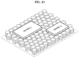
- FIG. 13 is a drawing illustrating an operation example when a plurality of devices is placed on the wireless charging pad illustrated in FIG. 1 .
- a plurality of devices i.e., “DEVICE 1” and “DEVICE 2,” may be placed on the wireless charging pad.
- small power transmission coils under “DEVICE 1” and “DEVICE 2” may be determined as power transmission coils to be driven, and coils surrounding the same may be determined as surrounding power transmission coils.
- FIG. 14 is a drawing illustrating an embodiment of a modular wireless charging pad according to an embodiment of the present disclosure.
- modules 1410 , 1420 , 1430 , 1440 , and 1450 are connected to each other, a wireless charging pad may be extended as much as needed, and a wireless chargeable area may be expanded in various shapes.
- FIG. 15 is an exemplary drawing illustrating an environment to which a wireless power transmission system according to an embodiment of the present disclosure is applied.
- a wireless power transmission environment may be a three-dimensional space such as a living room, a room, an office, an airport, or a train.
- power transmission may be near-field wireless power transmission using a magnetic induction method or a magnetic resonance method.
- a microwave method capable of covering near and far distances may be used.
- the power reception apparatus may be a communication device, and a three-dimensional space may be provided with an RF harvesting device capable of collecting energy from electromagnetic waves.
- FIG. 16 is a drawing illustrating a wireless power transmission apparatus capable of transmitting power in various ways in an environment similar to that illustrated in FIG. 15 .
- the wireless power transmission apparatus may include at least one of a wireless charging pad part 1610 , a near-field power transmitter 1620 , and a microwave power transmitter 1630 .
- FIG. 16 illustrates all of the wireless charging pad part 1610 , the near-field power transmitter 1620 , and the microwave power transmitter 1630 , a power transmission apparatus using one power transmission method may be provided depending upon a three-dimensional space environment.
- the wireless power transmission apparatus or power transmission apparatus in the present disclosure should be understood as including at least any one of the wireless charging pad part 1610 , the near-field power transmitter 1620 , and the microwave power transmitter 1630 .
- a controller 1640 may control operation of at least one of the wireless charging pad part 1610 , the near-field power transmitter 1620 , and the microwave power transmitter 1630 .
- the controller 1640 may monitor a three-dimensional space environment, and may control operation of at least one of the wireless charging pad part 1610 , the near-field power transmitter 1620 , and the microwave power transmitter 1630 based on the monitoring result.
- the controller 1640 may perform control such that the wireless charging pad part 1610 and the near-field power transmitter 1620 operate, but the microwave power transmitter 1630 does not operate.
- the wireless charging pad part 1610 may transmit power using a magnetic induction method or a magnetic resonance method.
- the wireless charging pad part 1610 may include the wireless charging pad constituted of a plurality of small power transmission coils and the driving device for the wireless charging pad, as described above with reference to FIGS. 1 to 14 .
- the near-field power transmitter 1620 may transmit power to a three-dimensional space using a magnetic resonance method.
- the microwave power transmitter 1630 may transmit power to a three-dimensional space using a microwave power transmission method.
- a far field may be defined as a case where a distance between a transmitter and a receiver is “2 ⁇ (antenna length) 2 /wavelength” or more.
- FIG. 17 is a drawing illustrating a configuration example of a near-field power transmitter illustrated in FIG. 16 .
- the near-field power transmitter may include a coil part 1710 including a plurality of power transmission coils; a power divider 1715 ; a first amplifier 1720 ; a second amplifier 1730 ; a phase shifter 1740 ; and a controller 1750 .
- the coil part 1710 transmits wireless power to a reception coil using a magnetic resonance method.
- the coil part 1710 may include two magnetic resonance coils 1711 and 1713 .
- the first and second magnetic resonance coils 1711 and 1713 may respectively form magnetic coupling with a single reception coil, thereby wirelessly transmitting power.
- Such an environment constituted of a plurality of transmission coils and a single reception coil may be referred to as a Multiple Input Single Output (MISO) system.
- MISO Multiple Input Single Output
- an environment constituted of a single transmission coil or a single transmitter and a single reception apparatus may be referred to as a Single Input Single Output (SISO) system.
- SISO Single Input Single Output
- the MISO system may more efficiently transmit power, and may exhibit superior performance even in an environment in which a power reception apparatus moves, compared to the SISO system.
- magnetic coupling may be greatly affected according to an arranged state of transmission coils and a reception coil.
- magnetic coupling may be formed without being greatly affected by an arrangement state of the transmission coils and the reception coil.
- the power divider 1715 may divide power from a power source and may output the divided power to the first amplifier 1720 and the phase shifter 1740 .
- the phase shifter 1740 may change a phase of input power.
- the phase shifter 1740 may adjust a phase of a current supplied to the second amplifier 1730 by adjusting a phase of an input current.
- phases of currents supplied to the first magnetic resonance coil 1711 and the second magnetic resonance coil 1713 may be differently adjusted.
- a difference between phases of currents supplied to the first magnetic resonance coil 1711 and the second magnetic resonance coil 1713 may be set to 0 to 180 degrees.
- FIG. 18 is a drawing illustrating an embodiment of a phase shifter illustrated in FIG. 17 .
- the wireless power transmission system may control a phase difference between two transmitters by dividing a signal of a transmission part into two powers through a power divider and then attaching a phase shifter 1800 to only one side thereof.
- the phase shifter 1800 for adjusting a phase difference has too low a frequency band to be constituted in a general manner using the length of a line, which makes it difficult to increase a size. To address this problem, a structure illustrated in FIG. 18 may be used.
- the wireless power transmission apparatus may divide power supplied from a power source, and may amplify the divided power having a first phase through a first amplifier.
- the wireless power transmission apparatus may adjust the divided power having the first phase to a second phase through a phase shifter, and then may amplify a power having a second phase through a second amplifier.
- the wireless power transmission apparatus may control the amplified power having the first phase and the amplified power having the second phase to be transmitted to a reception side through different resonant coils.
- the phase shifter 1800 may use variable capacitors to adjust the power having the first phase to have a second phase.
- the phase shifter 1800 includes a serial transmission line part 1801 and a parallel variable capacitor part 1802 .
- the phase shifter 1800 may include a first variable capacitor (2C v1 ) connected in series to an inductor (L 0 /2) and a second capacitor (2C v2 ) connected in parallel to a capacitor (C 0 ), as shown as drawing numeral 1801 .
- the power having the first phase divided using the first variable capacitor and the second variable capacitor may be phase-adjusted to have the second phase.
- a range of a phase shift may be determined according to a capacitance control range of the parallel variable capacitor part 1802 .
- the phase shifter 1800 is designed using a lumped element to also operate at low frequencies.
- the phase shifter 1800 has a wider phase shift width by simultaneously controlling inductors connected in series and capacitors connected in parallel through connection of variable capacitors in series and in parallel.
- the shifted phase and power which is output from the power divider, may generate different-magnitude powers through two power amplifiers, and then may supply the powers to the transmitter.
- a controller of a reception part may investigate reception power and adjust load resistance and provide reception power information through communication with the controller of the transmission part, and the controller of the transmission part may control a phase and the magnitude of power based on the information.
- the wireless power transmission apparatus may adjust load resistance of a reception part.
- MCU MicroController Unit
- the controller may request that a reception side to control load resistance of the reception side in consideration of optimum load resistance allowing reception of maximum power.
- the reception side may adjust load resistance by simultaneously controlling an inductor and a capacitor using a variable capacitor, or may adjust the load resistance through a selected matching circuit.
- the controller may request to adjust load resistance of the reception side at regular intervals so as to find a maximum efficiency state.
- the controller may adjust the load resistance of the reception side in consideration of both efficiency between a transmitter and a receiver and a constant cycle.
- a coupling coefficient between the receiver and the transmitter is changed according to an attitude of the receiver (an angle between the receiver and the transmitter) and a distance between the receiver and the transmitter, which changes optimal load resistance allowing reception of maximum power. Accordingly, other than control of a phase difference between the receiver and the transmitter and the magnitude of power, it is necessary to control the load resistance of the reception side. Therefore, a state in which a maximum efficiency is exhibited should be found while changing the magnitude and phase of the transmission part whenever the load resistance of the reception side changes.
- the load resistance of the reception side may be implemented by adjusting input impedance through an LC matching circuit.
- a method of simultaneously controlling the LC using a variable capacitor, as in the phase shifter is also possible.
- several matching circuits may be selected and implemented, and a matching circuit may be selected through switching.
- FIG. 19 is a drawing illustrating a configuration and operation environment of a microwave power transmitter illustrated in FIG. 16 .
- the microwave power transmitter may include an array antenna part 1930 including a plurality of antenna elements (element 1, element 2, . . . element N).
- the array antenna part 1930 may adjust radiation characteristics by controlling a phase and a magnitude of distribution current of each of the antenna elements.
- reception power may be maximized by adjusting a feeding phase of each radiation element so that the electric field is added in the same phase at a position of a reception antenna.
- a distance between an array antenna and a reception antenna is assumed to be very far. Accordingly, power transmission efficiency between the antennas may be calculated by applying the Friis formula represented by Equation 1, after assuming that a distance between each of the antenna elements of the array antenna and the reception antenna is equal:
- P r denotes reception power
- P t denotes transmission power
- R denotes a distance between the transmission antenna and the reception antenna
- G t denotes a gain of the transmission antenna
- G r denotes a gain of the reception antenna
- Friis formula might not be applied to an environment for near-field or intermediate-distance wireless power transmission because a distance between each of the antenna elements of the array antenna and the reception antenna is different.
- a controller 1540 or microwave power transmitter 1530 of FIG. 16 calculates power transmission efficiency considering an environment for actual wireless power transmission upon calculation of power transmission efficiency.
- the controller 1540 or microwave power transmitter 1530 of FIG. 16 may receive information on reception power through communication with the power reception apparatus, and may calculate power transmission efficiency based on Equation 2 below. In addition, the controller 1540 may calculate power transmission efficiency from a near distance to a far distance based on Equation 2.
- Equation 3 an average distance between a radiation element at a transmission end and a reception antenna.
- Equation 4 a power transmission efficiency calculation method according to an embodiment of the present disclosure
- driving of an individual coil may be freely controlled, whereby coils may be expanded into a more efficient shape.
- phase of driving coils and coils near the driving coils may be reversely controlled, the magnetic field spreading to the outside may be reduced, thereby reducing harm to the human body. Accordingly, the magnitude of transmission power may be increased, compared to related technologies.
- the wireless charging pad of the present disclosure may be modularized, the wireless charging pad may be fabricated in various sizes. Further, when a module is added, a separate additional control circuit is unnecessary.
- the aforementioned device may be realized by hardware component, a software component, and/or a combination of hardware and software components.
- the device and components described in the embodiments may be realized using one or more general-purpose computers or special-purpose computers such as, for example, a processor, a controller, an arithmetic logic unit (ALU), a digital signal processor, a microcomputer, a field programmable array (FPA), a programmable logic unit (PLU), a microprocessor, or other devices implementing instructions and responding thereto.
- the processor may execute one or software applications that run on an operating system (OS).
- OS operating system
- the processor may approach data, store, manipulate, and process the data, and generate new data by responding to running of software.
- processor may include a plurality of processing elements and/or a plurality of processing element types.
- the processor may include a plurality of processors or a combination of one processor and controller.
- another processing configuration such as a parallel processor, may be applied.
- Software may include a computer program, code, instructions, or a combination of one or more of the foregoing, and may configure a processing device to operate as desired or independently or collectively a command to a processing device.
- Software and/or data may be permanently or temporarily embodied in the form of any type of machines, components, physical devices, virtual equipment, computer storage media or devices, or a signal wave to be transmitted, so as to be interpreted by a processing device or to provide a command or date to a processing device.
- Software may be distributed over a networked computer system, and stored or executed in a distributed manner.
- Software and data may be stored on one or more computer readable media.
- Embodiments of the present disclosure can include a computer readable medium including program commands for executing operations implemented through various computers.
- the computer readable medium can store program commands, data files, data structures or combinations thereof.
- the program commands recorded in the medium may be specially designed and configured for the present disclosure or be known to those skilled in the field of computer software.
- Examples of a computer readable recording medium include magnetic media such as hard disks, floppy disks and magnetic tapes, optical media such as CD-ROMs and DVDs, magneto-optical media such as floptical disks, or hardware devices such as ROMs, RAMs and flash memories, which are specially configured to store and execute program commands.
- Examples of the program commands include a machine language code created by a compiler and a high-level language code executable by a computer using an interpreter and the like.
- the hardware devices may be configured to operate as one or more software modules to perform operations in the embodiments, and vice versa.
Landscapes
- Engineering & Computer Science (AREA)
- Computer Networks & Wireless Communication (AREA)
- Power Engineering (AREA)
- Signal Processing (AREA)
- Charge And Discharge Circuits For Batteries Or The Like (AREA)
Abstract
Description
Claims (7)
Applications Claiming Priority (2)
| Application Number | Priority Date | Filing Date | Title |
|---|---|---|---|
| KR1020170158841A KR20190060531A (en) | 2017-11-24 | 2017-11-24 | Method and apparatus for driving of a wireless charging pad including plurality of power transfer coil |
| KR10-2017-0158841 | 2017-11-24 |
Publications (2)
| Publication Number | Publication Date |
|---|---|
| US20190165608A1 US20190165608A1 (en) | 2019-05-30 |
| US10693319B2 true US10693319B2 (en) | 2020-06-23 |
Family
ID=66630690
Family Applications (1)
| Application Number | Title | Priority Date | Filing Date |
|---|---|---|---|
| US15/902,543 Active 2038-04-30 US10693319B2 (en) | 2017-11-24 | 2018-02-22 | Wireless charging pad including plurality of small power transmission coils and device for and method of driving wireless charging pad in wireless power transmission system |
Country Status (4)
| Country | Link |
|---|---|
| US (1) | US10693319B2 (en) |
| EP (1) | EP3716444A4 (en) |
| KR (1) | KR20190060531A (en) |
| WO (1) | WO2019103241A1 (en) |
Cited By (3)
| Publication number | Priority date | Publication date | Assignee | Title |
|---|---|---|---|---|
| TWI757968B (en) * | 2020-11-11 | 2022-03-11 | 寶德科技股份有限公司 | Mouse pad device |
| CN114546142A (en) * | 2020-11-11 | 2022-05-27 | 宝德科技股份有限公司 | Mouse pad device |
| US12374929B2 (en) * | 2020-09-09 | 2025-07-29 | Samsung Electronics Co., Ltd. | Electronic device for wirelessly transmitting power and operation method thereof |
Families Citing this family (7)
| Publication number | Priority date | Publication date | Assignee | Title |
|---|---|---|---|---|
| KR101947923B1 (en) * | 2017-12-21 | 2019-02-13 | 경희대학교 산학협력단 | Wireless power transmission system using patch antennas |
| CN112701802A (en) * | 2020-11-19 | 2021-04-23 | 国网浙江省电力有限公司宁波供电公司 | Wireless charging system and method for robot |
| JP7626991B2 (en) * | 2021-06-03 | 2025-02-05 | ローレルバンクマシン株式会社 | Wireless power supply system and method |
| JP7626060B2 (en) * | 2021-12-23 | 2025-02-04 | 豊田合成株式会社 | Auxiliary power receiving device |
| CN114050668B (en) * | 2022-01-07 | 2022-04-15 | 合肥有感科技有限责任公司 | Wireless charging transmitting device |
| CN114079326B (en) * | 2022-01-07 | 2022-04-08 | 合肥有感科技有限责任公司 | How wireless charging devices work |
| KR20240145427A (en) * | 2023-03-27 | 2024-10-07 | 현대자동차주식회사 | Wireless power transfer apparatus including coil structure for wireless power transfer and method therefor |
Citations (16)
| Publication number | Priority date | Publication date | Assignee | Title |
|---|---|---|---|---|
| US20070182367A1 (en) * | 2006-01-31 | 2007-08-09 | Afshin Partovi | Inductive power source and charging system |
| US20110025133A1 (en) * | 2008-04-03 | 2011-02-03 | Koninklijke Philips Electronics N.V. | Wireless power transmission system |
| US20120007437A1 (en) * | 2007-08-28 | 2012-01-12 | Access Business Group International Llc | Inductive power supply |
| KR20120117262A (en) | 2011-04-15 | 2012-10-24 | 현대자동차주식회사 | Wireless power transmission device for vehicle |
| WO2013020138A2 (en) | 2011-08-04 | 2013-02-07 | Witricity Corporation | Tunable wireless power architectures |
| KR20130026254A (en) | 2011-09-05 | 2013-03-13 | 엘에스전선 주식회사 | Apparatus for wireless power transmission using multi antenna and method for controlling thereof |
| US20130093253A1 (en) * | 2011-04-08 | 2013-04-18 | Access Business Group International Llc | Counter wound inductive power supply |
| US20130119773A1 (en) * | 2011-11-15 | 2013-05-16 | Qualcomm Incorporated | Systems and methods for induction charging with a closed magnetic loop |
| KR20130119585A (en) | 2012-04-24 | 2013-11-01 | 삼성전자주식회사 | Wireless power transmitting/receiving apparatus |
| KR20150055087A (en) | 2012-10-31 | 2015-05-20 | 미쓰비시 덴끼 엔지니어링 가부시키가이샤 | Multiplexed transmission system by means of wireless electrical power transmission, and transmitting-side multiplexed transmission device |
| WO2015123651A1 (en) | 2014-02-14 | 2015-08-20 | Massachusetts Institute Of Technology | Wireless power transfer |
| JP2016105690A (en) | 2008-07-28 | 2016-06-09 | クゥアルコム・インコーポレイテッドQualcomm Incorporated | Wireless power transmission for electronic devices provided with parasitic resonant tank |
| KR20160147238A (en) | 2016-10-31 | 2016-12-22 | 현대자동차주식회사 | Wireless charging system and method thereof |
| KR20170010870A (en) | 2017-01-18 | 2017-02-01 | 엘지이노텍 주식회사 | Apparatus for wireless power transmission and the control method thereof |
| US20170237296A1 (en) * | 2014-08-12 | 2017-08-17 | Powerbyproxi Limited | System and method for power transfer |
| US20180097404A1 (en) * | 2015-04-07 | 2018-04-05 | Lg Innotek Co., Ltd. | Wireless power transmission device and control method therefor |
Family Cites Families (2)
| Publication number | Priority date | Publication date | Assignee | Title |
|---|---|---|---|---|
| KR20160145152A (en) * | 2014-05-20 | 2016-12-19 | 후지쯔 가부시끼가이샤 | Wireless power transmission control method and wireless power transmission system |
| US10084321B2 (en) * | 2015-07-02 | 2018-09-25 | Qualcomm Incorporated | Controlling field distribution of a wireless power transmitter |
-
2017
- 2017-11-24 KR KR1020170158841A patent/KR20190060531A/en not_active Ceased
-
2018
- 2018-02-19 EP EP18881230.9A patent/EP3716444A4/en not_active Withdrawn
- 2018-02-19 WO PCT/KR2018/002019 patent/WO2019103241A1/en not_active Ceased
- 2018-02-22 US US15/902,543 patent/US10693319B2/en active Active
Patent Citations (19)
| Publication number | Priority date | Publication date | Assignee | Title |
|---|---|---|---|---|
| US20070182367A1 (en) * | 2006-01-31 | 2007-08-09 | Afshin Partovi | Inductive power source and charging system |
| US20120007437A1 (en) * | 2007-08-28 | 2012-01-12 | Access Business Group International Llc | Inductive power supply |
| US20110025133A1 (en) * | 2008-04-03 | 2011-02-03 | Koninklijke Philips Electronics N.V. | Wireless power transmission system |
| JP2016105690A (en) | 2008-07-28 | 2016-06-09 | クゥアルコム・インコーポレイテッドQualcomm Incorporated | Wireless power transmission for electronic devices provided with parasitic resonant tank |
| US20130093253A1 (en) * | 2011-04-08 | 2013-04-18 | Access Business Group International Llc | Counter wound inductive power supply |
| KR20120117262A (en) | 2011-04-15 | 2012-10-24 | 현대자동차주식회사 | Wireless power transmission device for vehicle |
| WO2013020138A2 (en) | 2011-08-04 | 2013-02-07 | Witricity Corporation | Tunable wireless power architectures |
| JP2014527793A (en) | 2011-08-04 | 2014-10-16 | ワイトリシティ コーポレーションWitricity Corporation | Tunable wireless power architecture |
| KR20130026254A (en) | 2011-09-05 | 2013-03-13 | 엘에스전선 주식회사 | Apparatus for wireless power transmission using multi antenna and method for controlling thereof |
| US20130119773A1 (en) * | 2011-11-15 | 2013-05-16 | Qualcomm Incorporated | Systems and methods for induction charging with a closed magnetic loop |
| KR20130119585A (en) | 2012-04-24 | 2013-11-01 | 삼성전자주식회사 | Wireless power transmitting/receiving apparatus |
| KR20150055087A (en) | 2012-10-31 | 2015-05-20 | 미쓰비시 덴끼 엔지니어링 가부시키가이샤 | Multiplexed transmission system by means of wireless electrical power transmission, and transmitting-side multiplexed transmission device |
| WO2015123651A1 (en) | 2014-02-14 | 2015-08-20 | Massachusetts Institute Of Technology | Wireless power transfer |
| US20150236526A1 (en) * | 2014-02-14 | 2015-08-20 | Massachusetts Institute Of Technology | Wireless power transfer |
| JP2017511102A (en) | 2014-02-14 | 2017-04-13 | マサチューセッツ インスティテュート オブ テクノロジー | Wireless power transmission |
| US20170237296A1 (en) * | 2014-08-12 | 2017-08-17 | Powerbyproxi Limited | System and method for power transfer |
| US20180097404A1 (en) * | 2015-04-07 | 2018-04-05 | Lg Innotek Co., Ltd. | Wireless power transmission device and control method therefor |
| KR20160147238A (en) | 2016-10-31 | 2016-12-22 | 현대자동차주식회사 | Wireless charging system and method thereof |
| KR20170010870A (en) | 2017-01-18 | 2017-02-01 | 엘지이노텍 주식회사 | Apparatus for wireless power transmission and the control method thereof |
Cited By (4)
| Publication number | Priority date | Publication date | Assignee | Title |
|---|---|---|---|---|
| US12374929B2 (en) * | 2020-09-09 | 2025-07-29 | Samsung Electronics Co., Ltd. | Electronic device for wirelessly transmitting power and operation method thereof |
| TWI757968B (en) * | 2020-11-11 | 2022-03-11 | 寶德科技股份有限公司 | Mouse pad device |
| CN114546142A (en) * | 2020-11-11 | 2022-05-27 | 宝德科技股份有限公司 | Mouse pad device |
| CN114546142B (en) * | 2020-11-11 | 2023-12-12 | 宝德科技股份有限公司 | mouse pad device |
Also Published As
| Publication number | Publication date |
|---|---|
| WO2019103241A1 (en) | 2019-05-31 |
| EP3716444A4 (en) | 2021-07-14 |
| KR20190060531A (en) | 2019-06-03 |
| US20190165608A1 (en) | 2019-05-30 |
| EP3716444A1 (en) | 2020-09-30 |
Similar Documents
| Publication | Publication Date | Title |
|---|---|---|
| US10693319B2 (en) | Wireless charging pad including plurality of small power transmission coils and device for and method of driving wireless charging pad in wireless power transmission system | |
| US9112367B2 (en) | Wireless power transmission system, method and apparatus for tracking resonance frequency in wireless power transmission system | |
| US10050479B2 (en) | Wireless power transmission system based on cell division | |
| JP2011528547A (en) | Adaptive matching and tuning of HF wireless power transmit antenna | |
| IL258001A (en) | Wireless charging platforms via three-dimensional phased coil arrays | |
| KR101916636B1 (en) | Apparatus and method of wirelessly transmitting power by confirming location of receiver | |
| KR20140098260A (en) | High efficiency and power transfer in wireless power magnetic resonators | |
| KR20190075431A (en) | Wireless power transfer system for wirelessly transferring power to power receiving apparatus by monitoring receiving power of power receiving apparatus | |
| KR102069097B1 (en) | Coil apparatus for generating magnetic field for wireless power transmission | |
| KR101945601B1 (en) | Method and apparatus for dynamic impedance matching in magnetic resonance type wireless power transfer system | |
| US20170187250A1 (en) | Electromagnetic wave radiation-based wireless power transmitter and wireless power transfer system using high gain antenna and beam forming and steering technology | |
| KR102042120B1 (en) | Phase shifter using tunable capactor and wireless power transmission system using the same | |
| US10707685B2 (en) | Resonant cavity mode enabled wireless power transfer | |
| KR101986050B1 (en) | Impedance matching apparatus included in wireless power transmission system and operating method thereof | |
| KR101932383B1 (en) | Wireless power transfer apparatus using metamaterial and loop coil array and method thereof | |
| KR102039864B1 (en) | Wireless power transmission system using meta-structure transmission lines | |
| KR101958595B1 (en) | Control appartus of array antenna for enhancing wireless power transmission efficiency and control method thereof | |
| US20190199146A1 (en) | Magnetic field generating apparatus having cannon shape and magnetic field generation method thereof | |
| US10855114B2 (en) | Wireless power transmission system using patch antenna | |
| KR102051270B1 (en) | Wireless power transmission system for improving degree of freedom of receiver | |
| Jolani et al. | A novel planar wireless power transfer system with strong coupled magnetic resonances | |
| KR102087302B1 (en) | Foldable coil apparatus with high efficiency and low electromagnetic field mode | |
| KR101967580B1 (en) | Method and apparatus for controlling input current and input phase for improving degree of freedom of receiver in wireless power transmission system | |
| KR102067731B1 (en) | Expandable block type coil appartus | |
| KR102241907B1 (en) | Wireless power transmission system using one body type transceiver module |
Legal Events
| Date | Code | Title | Description |
|---|---|---|---|
| AS | Assignment |
Owner name: UNIVERSITY-INDUSTRY COOPERATION GROUP OF KYUNG HEE Free format text: ASSIGNMENT OF ASSIGNORS INTEREST;ASSIGNORS:HONG, EEN KEE;KIM, JOON HWAN;LEE, BOM SON;AND OTHERS;REEL/FRAME:045007/0993 Effective date: 20180222 Owner name: UNIVERSITY-INDUSTRY COOPERATION GROUP OF KYUNG HEE UNIVERSITY, KOREA, REPUBLIC OF Free format text: ASSIGNMENT OF ASSIGNORS INTEREST;ASSIGNORS:HONG, EEN KEE;KIM, JOON HWAN;LEE, BOM SON;AND OTHERS;REEL/FRAME:045007/0993 Effective date: 20180222 |
|
| FEPP | Fee payment procedure |
Free format text: ENTITY STATUS SET TO UNDISCOUNTED (ORIGINAL EVENT CODE: BIG.); ENTITY STATUS OF PATENT OWNER: SMALL ENTITY |
|
| FEPP | Fee payment procedure |
Free format text: ENTITY STATUS SET TO SMALL (ORIGINAL EVENT CODE: SMAL); ENTITY STATUS OF PATENT OWNER: SMALL ENTITY |
|
| STPP | Information on status: patent application and granting procedure in general |
Free format text: DOCKETED NEW CASE - READY FOR EXAMINATION |
|
| STPP | Information on status: patent application and granting procedure in general |
Free format text: NON FINAL ACTION MAILED |
|
| STPP | Information on status: patent application and granting procedure in general |
Free format text: RESPONSE TO NON-FINAL OFFICE ACTION ENTERED AND FORWARDED TO EXAMINER |
|
| STPP | Information on status: patent application and granting procedure in general |
Free format text: FINAL REJECTION MAILED |
|
| STPP | Information on status: patent application and granting procedure in general |
Free format text: NOTICE OF ALLOWANCE MAILED -- APPLICATION RECEIVED IN OFFICE OF PUBLICATIONS |
|
| STPP | Information on status: patent application and granting procedure in general |
Free format text: PUBLICATIONS -- ISSUE FEE PAYMENT VERIFIED |
|
| STCF | Information on status: patent grant |
Free format text: PATENTED CASE |
|
| MAFP | Maintenance fee payment |
Free format text: PAYMENT OF MAINTENANCE FEE, 4TH YR, SMALL ENTITY (ORIGINAL EVENT CODE: M2551); ENTITY STATUS OF PATENT OWNER: SMALL ENTITY Year of fee payment: 4 |