US1069176A - Typograph. - Google Patents
Typograph. Download PDFInfo
- Publication number
- US1069176A US1069176A US57730410A US1910577304A US1069176A US 1069176 A US1069176 A US 1069176A US 57730410 A US57730410 A US 57730410A US 1910577304 A US1910577304 A US 1910577304A US 1069176 A US1069176 A US 1069176A
- Authority
- US
- United States
- Prior art keywords
- mold
- matrix
- tho
- pot
- metal
- Prior art date
- Legal status (The legal status is an assumption and is not a legal conclusion. Google has not performed a legal analysis and makes no representation as to the accuracy of the status listed.)
- Expired - Lifetime
Links
- 239000011159 matrix material Substances 0.000 description 34
- 239000002184 metal Substances 0.000 description 29
- 238000005266 casting Methods 0.000 description 16
- 239000002131 composite material Substances 0.000 description 16
- 230000000750 progressive effect Effects 0.000 description 9
- OHYPPUOVSUINHM-UHFFFAOYSA-N 4-(methylamino)phenol;sulfuric acid Chemical compound OS(O)(=O)=O.CNC1=CC=C(O)C=C1 OHYPPUOVSUINHM-UHFFFAOYSA-N 0.000 description 1
- 240000000662 Anethum graveolens Species 0.000 description 1
- 235000004936 Bromus mango Nutrition 0.000 description 1
- 241001459693 Dipterocarpus zeylanicus Species 0.000 description 1
- 241000237858 Gastropoda Species 0.000 description 1
- LFVLUOAHQIVABZ-UHFFFAOYSA-N Iodofenphos Chemical compound COP(=S)(OC)OC1=CC(Cl)=C(I)C=C1Cl LFVLUOAHQIVABZ-UHFFFAOYSA-N 0.000 description 1
- 240000007228 Mangifera indica Species 0.000 description 1
- 235000014826 Mangifera indica Nutrition 0.000 description 1
- 241000282320 Panthera leo Species 0.000 description 1
- 235000009184 Spondias indica Nutrition 0.000 description 1
- 238000010276 construction Methods 0.000 description 1
- 238000001816 cooling Methods 0.000 description 1
- 239000007789 gas Substances 0.000 description 1
- 238000007689 inspection Methods 0.000 description 1
- 238000004519 manufacturing process Methods 0.000 description 1
- 238000009877 rendering Methods 0.000 description 1
Images

Classifications
-
- B—PERFORMING OPERATIONS; TRANSPORTING
- B41—PRINTING; LINING MACHINES; TYPEWRITERS; STAMPS
- B41B—MACHINES OR ACCESSORIES FOR MAKING, SETTING, OR DISTRIBUTING TYPE; TYPE; PHOTOGRAPHIC OR PHOTOELECTRIC COMPOSING DEVICES
- B41B11/00—Details of, or accessories for, machines for mechanical composition using matrices for individual characters which are selected and assembled for type casting or moulding
- B41B11/52—Moulding or casting devices or associated mechanisms
Definitions
- Ludlow typograph one form of which will be found described in U. S. Patent No. 856,539, issued to Washington I. Ludlow, June 11, 1907';
- a plurality of matrix bars are employed, such bars being longitu-' ,dina-lly. arranged in a trough and normally freely movable over a casting slot in such trough so that by suitably composing, or collecting,jsaid bars so as to bring over said slot any desired series of characters, a matrix for a type line of the width of a column of printed matter is formed.
- the object of the present invention is the provision of a casting mechanism in con- Junction with such typograph, proper, that will be convenient in use and at the same time embody various operative features conducing to the production of slugs or lines-0f type of superior quality.
- the matrix bars by means of which the matrix for the type-line or slug that the machine is designed to cast is formed, are supported on a bed plate or top.
- This top A is n'rovably secured to the frame proper of the machine, being preferably hinged thereto along its rear edge, so that-it can be turned back along with the parts su 'iportcd thereon.
- Such top furthermore, inclines dowmvardly and forwardly at'an angle approximately that shown in Figs. 3 and 4', so as to place the aforesaid bars in position for convenient inspection and manipulation on the part of the operator.
- a trough-like depression a is formed in the top for the reception of the bars, such trough hayinga transverse opening or slot a into which a mold (J is adapted to project,
- the casting pot B which is designed to to supply slug, comprisesan inner chamber 15 adapted to contain the molten metal, such chamber being of general cylindrical form and including a sub-chamber 6 adapted .to receive a piston or plunger 6. From such sub-chamber-a spout 0 extends forwardly and upwardly, it being through this that the metal is forced into the mold in the actual operation of casting. Connnunication between the chamber and the sub-chamber, holding the plunger, is furnished b a series of apertures? in the walls of such latter chamber, which apertures are closed as the plunger descends.
- tension spying Z) l'lml is oonniclcd through a rod 7) and lower 71 ⁇ vil'h mid plum-- gci' lo depi' 1; the some, but norn'zzilly held from such actuation of the plunger by means of a com H on the. com or main drive shalt ll.
- Said cum operates lhrough 4 u. rockshnl'l: B and suitable lovers 5 h i'cspcotii'cly cooperative with said coin and conncci'od with tho rod 5, as need not he f nl'l'lQl explained.
- the cooling pol is furihormoro supported upon :1 universal joint 5 about which ii; in movuhlc so to periodically hiring who outer and of rho ousting spoutb into register T'Jl'lLl'l. tho under side of lhe mold. when he lollci. supported in opomtivo position in the slot of (he. matrix l'i'ough.
- Such inoiunonl: of l'ho pot involves l'ho shiflii '3; of the upon? him alincuicnlx Willi the mold.
- the casting pol is conncclcd with said drum by moons of a. pin 52" suitohly ot'lachecl l'o lho front face of tho pot. Accordingly as the drum rot-ales, not only will tho costing pot he swung horizontally lhi'ough 3Y0 corrospmuling lo the laiioxol displnccmcnt of? Lhc groove on tho dcums face, but also be tilled up and down 'to'com'copond with lhe dillor- (uccS in radius hclweon lhoulil'l'ci'cut ports of: said (lrums surface. surface are conformed to produce .lhc desired lateral shifting and up-ond-down movement of the spout of tho pol, as will be readily understood.
- the discharge and of tho spoul carries a squirt plate b of usual construction, which directly contacts with the mold and has a finished surface for tho purposoof making the joint with the mold" metal-tight, being provided with a. series of apertures through which tho molol is forced into the mold.
- flue 3 con forming with tho general inclination ports previously monlionod. provides o natural Way of escopo for the gases the open nozzlo-oncloi the po l; in its: inopemtive position.
- Olher loo-d s osplying she principle of my invoniiou may we employed iusl'cod of the one oxploinecl, change lacing made as re ill-5,
- a slug casting mold having a face adapted to contact with a matrix; and means adapted to supply molten metal to said mold, the latters matrix-contacting face being disposed with its longitudinal axis'inclined to the horizontal, whereby such metal is brought into progressive contact with such 'face.
- the combination ,ofmatrix-bearing members adapted to be assembled to form'a composite matrix fora line of type, such composite matrix being directed downwardly and being disposed with its longitudinal axis inclining in a vertical plane; a slug casting mold cotiperat-ive with such composite matrix; and meansadapted to supply molten metal to said mold, such metal being brought into progressive contact with said matrix by reason of the latters inclination.
- a slug-casting mold having its matrixscontactmg face, disposed with its longitudinal axis inclined to :the horizontal; a pot for .molten metal movably mounted below and to the rear of the elevated end of said mold,'and having a spout adapted, in one position of said pot, to register with said mold from below; and means for forcing metal from said .pot into said mold, such metal. being brought into progressive contact with the matrix, byreason of the inclinatipn of such matrix-contacting. face.
- a slug-casting mold having its matrix-contactingface disposed with its longitudinal axis inclined to the horizontal; a pot for molten metal mounted on a universal joint below and to the rear of' the elevational end of said mold, and having a spout, adapted in one position of said pot, to register with said mold from below; and means for forcing metal from said pot into said mold, such metal being brought. into progressive contact with the matrix, by reason of the inclination of such matrix-contacting face.
Landscapes
- Molds, Cores, And Manufacturing Methods Thereof (AREA)
Description
W. A. READE,
TYPOGRAPH. APPLICATION FILED AUG.15,1910.
Patented Aug. 5, 1913.
2 SHEETSSHEET 1.
ill]
WITNESSES:
3. ATTOAWEV UNITED sTArEs PATENT OFFICE.
WILL AM A. READE, or CLEVELAND, OHIO, ASSIGNOR TO THE LUnLo'w TYPOGRAPI. COMPANY, or CLEVELAND, OHIO, A CORPORATION or MAINE.
' TYPOGRAPH.
' Specification of Letters Patent.
Patented Aug. 5, 1913.
Application filed August 15 1910. Serial No. 577,304.
To all whom it may concern:
Be it known that I, WILLIAM vA. READE, a citizen ofthe' United States, and a resident of Cleveland, county of '(Juyahoga, and State of Ohio, have invented a new and useful Improvement in Typographs, of which the following is a specification, the principle of the invention being herein explained and the best mode in which I have contemplated applying that rinciple, so as to distinguish it from 0t er inventions.
' The present improvements relate more particularly to the Ludlow typograph, one form of which will be found described in U. S. Patent No. 856,539, issued to Washington I. Ludlow, June 11, 1907'; In such Ludlow typograph a plurality of matrix bars are employed, such bars being longitu-' ,dina-lly. arranged in a trough and normally freely movable over a casting slot in such trough so that by suitably composing, or collecting,jsaid bars so as to bring over said slot any desired series of characters, a matrix for a type line of the width of a column of printed matter is formed.
The object of the present invention is the provision of a casting mechanism in con- Junction with such typograph, proper, that will be convenient in use and at the same time embody various operative features conducing to the production of slugs or lines-0f type of superior quality.- Y
To the accomplishment of the foregoing and related ends, said invention then consists of the means hereinafter full described and particularly pointed out in the claims.
The annexed drawings and the following description set forth in detail certain mechanism embodying the invention, such disclosed means constituting, however, but one of Various mechanical forms in which the principle of the invention may be used.
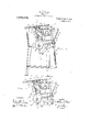
In said annexed drawings :--Figure l is a part front elevation and part section of my improved typograph and slug, casting mechanism, the plane of thc'scction being indicatedbythe line l1, Figs. 3 and l; Fig.- 2 is a similar view but showing the parts in different operative position; Fig. 3 is a transverse vertical section of such mechanism; Fig. 4 is a similar transvers section, but showing certain parts in a different operative position; and Fig.5 is a section of a cooperate with such slot 0 in order thereto the molten metal for forming the.
detail taken on the same plane as Figs. 3 and 4, but on a larger scale.
It has already been indicated that the matrix bars, by means of which the matrix for the type-line or slug that the machine is designed to cast is formed, are supported on a bed plate or top. This top A is n'rovably secured to the frame proper of the machine, being preferably hinged thereto along its rear edge, so that-it can be turned back along with the parts su 'iportcd thereon. Such top, furthermore, inclines dowmvardly and forwardly at'an angle approximately that shown in Figs. 3 and 4', so as to place the aforesaid bars in position for convenient inspection and manipulation on the part of the operator.
A trough-like depression a is formed in the top for the reception of the bars, such trough hayinga transverse opening or slot a into which a mold (J is adapted to project,
so that its upper surface will lie flush with the bottom of the trough and not interfere with the free movement of the bars (1, across the same. The various movements of the mold whereby a slug, after being formed therein, is charged, are not of present interest and so will not be described. Such mold, however, will obviously conform with the inclination .of the top A or'rather of trough a therein,
which holds the 'bar's; that is the slot 0 in the mold will incline forwardly and down- 'wardly.
The casting pot B, which is designed to to supply slug, comprisesan inner chamber 15 adapted to contain the molten metal, such chamber being of general cylindrical form and including a sub-chamber 6 adapted .to receive a piston or plunger 6. From such sub-chamber-a spout 0 extends forwardly and upwardly, it being through this that the metal is forced into the mold in the actual operation of casting. Connnunication between the chamber and the sub-chamber, holding the plunger, is furnished b a series of apertures? in the walls of such latter chamber, which apertures are closed as the plunger descends. Substantially en-" tirely surrounding the'inner chamber, and preferably cast integral therewith, are the walls of the pot proper, which thus provide removed, trimmed and dis-v spout will uhlc limiting inci'lium, \i'hoi-ch (he innci' whumhci' of ihc pol; may ho uiuinluincrl at l l ul'li-i zii'c pi'i'n'idcrl for pci'imlii'ully oclu uling tho 11li11l1(*1' Z1 lo fol-co molion iu lul up lluiough lhc spool ouch incauis consi 111g of a. tension spying Z) l'lml; is oonniclcd through a rod 7) and lower 71 \vil'h mid plum-- gci' lo depi' 1; the some, but norn'zzilly held from such actuation of the plunger by means of a com H on the. com or main drive shalt ll. Said cum operates lhrough 4 u. rockshnl'l: B and suitable lovers 5 h i'cspcotii'cly cooperative with said coin and conncci'od with tho rod 5, as need not he f nl'l'lQl explained. i
The cooling pol is furihormoro supported upon :1 universal joint 5 about which ii; in movuhlc so to periodically hiring who outer and of rho ousting spoutb into register T'Jl'lLl'l. tho under side of lhe mold. when he lollci. supported in opomtivo position in the slot of (he. matrix l'i'ough. Such inoiunonl: of l'ho pot involves l'ho shiflii '3; of the upon? him alincuicnlx Willi the mold. raising the some lhcrcoguinst, lfihcn lon'ci'ing lho spout and shilling iho some aside, tin-so several movements being accomplished lhrough lho :iglom'y of o. drum Pl" cormotl hi the. cam shalt ll. tho Gilli-91",,Slllffi09 of which drum is of" varying Tadius and hears a. groovo is. dillcrcnlly locolcd axially of lh-e com ohu'ft in ilifl'oi'cni polls of the drum. The casting pol; is conncclcd with said drum by moons of a. pin 52" suitohly ot'lachecl l'o lho front face of tho pot. Accordingly as the drum rot-ales, not only will tho costing pot he swung horizontally lhi'ough 3Y0 corrospmuling lo the laiioxol displnccmcnt of? Lhc groove on tho dcums face, but also be tilled up and down 'to'com'copond with lhe dillor- (uccS in radius hclweon lhoulil'l'ci'cut ports of: said (lrums surface. surface are conformed to produce .lhc desired lateral shifting and up-ond-down movement of the spout of tho pol, as will be readily understood.
The discharge and of tho spoul carries a squirt plate b of usual construction, which directly contacts with the mold and has a finished surface for tho purposoof making the joint with the mold" metal-tight, being provided with a. series of apertures through which tho molol is forced into the mold.
Not only is the machine top with the. body of bars carried thereon and tho mold that cooperates with said hora inclined in a forward and downward dii'rcu as 21mm ilcl'mo ilv;-':m-ihcd, but the l? ofooui which lho ousting pot swu n to m w shill. ifs spout, is inclined from ihc w a... lfi vmrrcspond. As i'osuit the cod of such spoui' is nol opprociuhl iuisod in h swung from its normal posilion. lhzil; 0? Fig". 2, to 11$: OPQIlllJVl? posiliou shown 2h d by a proper arrui'igcnwnt ihul 'l'ho invi'nl, since. if; picscifvcs a level SYZIFACE, us "ll woos: through tho squirt plain 6 into such. 510% in the mold, will first sl'rilzo the lower and forward cud of the composite provided by -11. Fig. 5),
the usucinhicd hum. (soc line 11 and iihon as such lcvol tho IllEl'ill. rises. the point of oonloch will llR'VGl up'oui'dly and so progrcusivoly along tho'n'ioir'ti usitil its onlirc loco is POYOP0l and tho mold filled, us indicalcd by tho line on l'hc some figure. .s'lny possibility of air huhhlcs or on foreign matter being cuughl'. on tho oi the umli'iiz. 1.. thus practically climb noted and a clear clcnn' cut impression surod. 1 Ji'flfi from iho udmnliugc thus ohlainod in the handling; of the inolol and Us iuliroducljioh. into i'hc costiog; slot, oll'euliou has already been called to the convouioucc in operation gained h liming lhc log of tho l'nuchino incline-d so 35; lo lPXllTlGl the: ham, and such. olhor purls (not shown} us are required to compose will look them in assembled positioznwoodily ucceusihlo nod easily manipulated. in; the some limo loo the heat and objectionable vapors that rise from the casting; pol, m'o caused to {low lo the rear and so a. thorough voulilul'ion of lhe machine is assured. lu olhcr i'vords, any lohdenoy such so is npl to he pi- :enlfi, whom tho top is sliioely hoi'izoulal, for such vapors to rise dii'ecl'ly upwardly, or oven to escape by tho 'l'l ont edge oflho top, is avoided, and o natural com-so lo the Tom? provided instead. Thus; flue 3:, con forming with tho general inclination ports previously monlionod. provides o natural Way of escopo for the gases the open nozzlo-oncloi the po l; in its: inopemtive position.
All lho foi'cgoihg advantages conli-ihulc lo rendering my improved lyoogi-ziph and ilSllllg' mochonism thcvol oi" efficient. and convenient in use.
Olher loo-d s osplying she principle of my invoniiou may we employed iusl'cod of the one oxploinecl, change lacing made as re ill-5,
longitudinal axis incline axis inclining in 12.
gards the mechanism herein disclosed, .provided the means stated by any of the following claims or the equivalent of such stated means be employed.
I therefore particularly point out and distinctly claim as my invention:
1. In mechanism of the class described, the combination of a slug casting mold having a face adapted to contact with a matrix; and means adapted to supply molten metal to said mold, the latters matrix-contacting face being disposed with its longitudinal axis'inclined to the horizontal, whereby such metal is brought into progressive contact with such 'face.
2. In mechanism of the class described, the combination of a mold having a face adaptedto contact with a matrix .for casting a line of type; and means adapted to supply molten metal to said mold frombelow, said molds matrix contacti face having its 7 d tothe horizontal, whereby such metal is brought intoprogressive contact with such face.
3. In mechanism of the class described, the combination ,ofmatrix-bearing members adapted to be assembled to form'a composite matrix fora line of type, such composite matrix being directed downwardly and being disposed with its longitudinal axis inclining in a vertical plane; a slug casting mold cotiperat-ive with such composite matrix; and meansadapted to supply molten metal to said mold, such metal being brought into progressive contact with said matrix by reason of the latters inclination.-
4. In mechanism of the class described, and the combination of matrix-bearing members adapted to be assembled to form a composite matrix for ajline of type, such composite matrix bein and being dispose with its longitudinal vertical plane; a slug casting mold having a vertical slot adapted to register at its upper end with such composite matrix; and means adapted to supply molten metal to such mold-slot from below, such metal being brought into progressive contact withsaid matrix-by reason ofv the latters inclination.
5. In mechanism of the combination of a support lying in a planeinclined from the horizontal; bars longitudinally movable in a horizontal direction on ,saldsupport and having matrices on their lower edges adapted to form a transversely disposed, composite. matrix for a line of type, such composite matrix being disposed with its longitudinal axis inclining to correspond with such support; a slug casting mold cotiperative wit such composite matrix; and means adapted to supply molten metal to said mold, such metal being brought into progressive contact with said matrix by reason of the latters inclination.
the class described,
directed downwardly.
tcr at its upper end with suchcomposite matrix; and means adapted to supply .molten metal to such mold-slot from below. such metal being brought into progressive contact with said matrix by reason of the latters inclination.
7. In mechanism of the class described, the combinationiof a slug-casting mold having its matrixscontactmg face, disposed with its longitudinal axis inclined to :the horizontal; a pot for .molten metal movably mounted below and to the rear of the elevated end of said mold,'and having a spout adapted, in one position of said pot, to register with said mold from below; and means for forcing metal from said .pot into said mold, such metal. being brought into progressive contact with the matrix, byreason of the inclinatipn of such matrix-contacting. face.
8. In mechanism of the .class described, the combination of a slug-casting mold having its matrix-contactingface disposed with its longitudinal axis inclined to the horizontal; a pot for molten metal mounted on a universal joint below and to the rear of' the elevational end of said mold, and having a spout, adapted in one position of said pot, to register with said mold from below; and means for forcing metal from said pot into said mold, such metal being brought. into progressive contact with the matrix, by reason of the inclination of such matrix-contacting face.
9. In mechanism of the class described, the combination of matrix-bearing members adapted to be assembled to form a composite matrix for a line of type, such com posite matrix bein .directed downwardly with its longitudina axis inclining in a vertical plane; a slug casting mold cooperative with such composite u molten metal movably mounted below and to the rear of said mold, and having a spout adapted inone position of said pot to register with said mold from below; and means for forcing metal from said 0t into the mold, such metal bein broug 1; into progressive contact with of the latters inclination.
10. In mechanism of the class described,
the combination of matrix-bearing members adapted to be assembled to form a composite matrix; and a pot for said matrix, by reason V CU-- odmol 13215; 10211 piano; a slug: costing i mposite matrix: 1 with its longi tool slot adaptor]. to re"- 7 mad with $511 71. mango I 1 for molten imtfll Hitilli'llLtCl. on a. ooivomol joint loolow 2 id to tho roar of the elevated end of said 1 old and a spool adapted in. one position of said pot to i' liter with said. nimld-sl0t f. om below; sons for filming metal from said pot into d. n'ioldslot such metal belo .IJTOUgll'iZ into ping! .sswo Contact with said 1:. reason oi? the latters inclination.
11. lo BIGGl'itlDlSJT: of the Gloss described, tho iibimitioii of :1 support lying in a plan ioclir l from llOllZOIliT:ll 5 bn.
lliii. ally 1 owil'ilo in :1 liOl'lP'L dill. d rod lion on said support and lziti'llig' iHHl L'iC-PS on lilioii lows? odd y l to form :1 ix m nmtrix for 1 matrix being diiml axis inclining so pport 2i slug cast- 1th such vompoiit'o mot and :i pot :iior molton mo! mov- 1' wotod boiow an to the rear ,1" said mold, and having o not adapted in one position of pot to register with mold fi'oiii below: and 1116111154 or fore t! motol from. said pot into snial mold, sucli l the CfilnblllitlllOil of a table having a longi--' tudinnlly extending trough, sold table in olining from tho horizontal in a direction transverse, of such trough; bars longitudinally movable in such. trough and moving nmtrices on their lower edges adapted to form; a tzransx ersely disposed, composite mm trix for a line of typo, such composite mabeing disposed with its longitudinal ncining to correspond with said table; slug casting mold having a vertical slot adapted to registor at its upper end with such cmnposito matrix; and a pot for molten metal numntod on a. universal joint below spout adapted in one position of said pot loregister With-said mold-slot from below; and means for forcing metal from said pot into said mold-slot, such metal being brought into progressive Contact with said matrix by reason of the lattors inclination,
Signed by ine'tliis 152th day of August, 1919.
' VILl'Jllill i A.;RE;IKDE. xittested' by- ANNA l \JlILL, 51x0. 1*. Oimmilw md to the 176211 of said mold and having a
Priority Applications (1)
| Application Number | Priority Date | Filing Date | Title |
|---|---|---|---|
| US57730410A US1069176A (en) | 1910-08-15 | 1910-08-15 | Typograph. |
Applications Claiming Priority (1)
| Application Number | Priority Date | Filing Date | Title |
|---|---|---|---|
| US57730410A US1069176A (en) | 1910-08-15 | 1910-08-15 | Typograph. |
Publications (1)
| Publication Number | Publication Date |
|---|---|
| US1069176A true US1069176A (en) | 1913-08-05 |
Family
ID=3137414
Family Applications (1)
| Application Number | Title | Priority Date | Filing Date |
|---|---|---|---|
| US57730410A Expired - Lifetime US1069176A (en) | 1910-08-15 | 1910-08-15 | Typograph. |
Country Status (1)
| Country | Link |
|---|---|
| US (1) | US1069176A (en) |
-
1910
- 1910-08-15 US US57730410A patent/US1069176A/en not_active Expired - Lifetime
Similar Documents
| Publication | Publication Date | Title |
|---|---|---|
| US1069176A (en) | Typograph. | |
| US1442059A (en) | Machine | |
| US1155137A (en) | Matrix-setting and line-casting machine. | |
| US2530832A (en) | Key-frame for key-operated musical instruments | |
| US978874A (en) | Automatic car weighing and recording scale. | |
| US1103363A (en) | Typographical machine. | |
| US1355089A (en) | Electeic typewriter | |
| US1146278A (en) | Composing mechanism for typographs. | |
| US335887A (en) | Elsbekg | |
| US1282109A (en) | Matrix for type-casting machines. | |
| US169757A (en) | Improvement in type-writing machines | |
| US797412A (en) | Linotype-machine. | |
| US547633A (en) | dodge | |
| US312145A (en) | merg-enthaler | |
| US429867A (en) | Casper l | |
| US1364045A (en) | Mold for type-casting machines | |
| US921946A (en) | Type-setting and printing machine. | |
| US1084795A (en) | Typographical composing-machine. | |
| US643292A (en) | Linotype-machine. | |
| US843578A (en) | Matrix-making, means to position plates and blocks. | |
| US700022A (en) | Linotype-matrix. | |
| US854457A (en) | Matrix-making master-block. | |
| US478258A (en) | Matrix-making machine | |
| US429864A (en) | Is peters co | |
| US40076A (en) | Improvement in molds for |