US1069152A - Printing mechanism for adding-machines. - Google Patents
Printing mechanism for adding-machines. Download PDFInfo
- Publication number
- US1069152A US1069152A US440399A US1908440399A US1069152A US 1069152 A US1069152 A US 1069152A US 440399 A US440399 A US 440399A US 1908440399 A US1908440399 A US 1908440399A US 1069152 A US1069152 A US 1069152A
- Authority
- US
- United States
- Prior art keywords
- type
- key
- actuator
- plate
- shaft
- Prior art date
- Legal status (The legal status is an assumption and is not a legal conclusion. Google has not performed a legal analysis and makes no representation as to the accuracy of the status listed.)
- Expired - Lifetime
Links
Images


Classifications
-
- G—PHYSICS
- G06—COMPUTING OR CALCULATING; COUNTING
- G06C—DIGITAL COMPUTERS IN WHICH ALL THE COMPUTATION IS EFFECTED MECHANICALLY
- G06C11/00—Output mechanisms
- G06C11/04—Output mechanisms with printing mechanisms, e.g. for character-at-a-time or line-at-a-time printing
Definitions
- Tou/'uJ/Ljofflfit may concer/n.:
- I Fig; 2 is a side e evation of the parts. with the handle omitted,the casing being shown in fr..trasection Fig. 3 isa1 central vertical sere-n on the plane of the line '3f-3 iuF 1g.
- Fig. 10 is a rear elevation of the' parts shouf-n in Fig. 9; Fig. 11 is a perspective detail, anil Fig. 12 is a perspective detail of the l rc stt-'ni 5 restoring spring.
- Fig. 17 is a top plan viewl of aracl; and type plate; Fig. 18 1s a transverse. scc.
- FIG. 19 is a detail perspective of a type; Fig-.20.
- Fig. 21 is a side elevation of the upp'er part of the rack and'typc plate guide post
- Fig. 22 is a side elevation of the rack and type plate guide post.
- Fig. 23 is a side elevation o-f a rack and type plate
- G.- 24 isla rear elevation of the saine; Fig. is an en" larged transverse section ofn .the plane ofthe line 25 ⁇ 25 1n Fig. 23; F1g.'2.6 v1s an enlarged lane ofthe line of the upper part Vof a-rack and type plate,
- Fig. 28 is a front elerationof the parts' shown in Fig. 27 ';
- Fig. 29 is a perspective des tail of a type actuator;
- Fig. 30 is a detail ing mechanism;
- Fig. 32 ⁇ is a rear View ofthe prior to the reversing movement;
- Fig; is
- Fig. 31 is a top plan view-of the -ribbonfeed-- 'parts shownin F ig. 31; Fig. 33 a .plan 'View of theribbon feed reversing lever; F ig. 5.
- '34s is a horizontal central section and partiat top plan'view of the ribbonspoolsand types tro ' a side elevation' of the partsshown in- Figs..
- Figs. Hand 4:2 are details of the restoring bar elbows; Fig. i3 is a side elevation of the.
- Fig- 45 is a detailZ of the multiple detent cross sha-ft';Fig46 if.
- organes-Ch stem 13 isqhmged-ioone -A of alielbow lever ⁇ 15 pivoted at 16 to the ;-plate 4, the l other endV of VWhieh “.lever is hinged to aA horizontal sto-p bar"9, the rear end of whichpasses through the aperture 8 provided -for that purpose finlthe guide. plate.
- release-bar 26 pivotedi tofa release leveri27j'-- j ingxf-rom a plate 30 mounted under' 4the up?.- per. partl of the easing.
- the lever .f2'( ⁇ "liasi al y nger piece 3l' jvvithfw'hioh has aSl-Qttd conneetion.
- Such movement causes the tip 11 to impinge against the lever 43 and oscillates it on its pivot 42 moving the hook 46 out of the path of a projection on the rack and type plate 81, hereinafter referred to, permitting the latter to rise until such projection contacts with the end of the bar 9, which has been moved rearwardly by the depression of the key referred to.
- the accumulating mechanism consists of the numeral wheels and their connections.
- the numeral wheels are arranged at the rear 1 of-the key system and in the upper part of the casing.
- Each wheel is provided with a disk 67 having peripheral recesses, a pinion 61, and a cam plate 62, each made integral therewith, or-secured thereto in any suitable manner.
- 1t is centrally apertured and loosely mounted to revolve on a shaft 63 secured to and projecting laterally from an arm 64 which 1n turn is mounted on a pivot 65 projecting laterally from a sup porting plate 66.
- Each arm 64 has a tail 53, and at its rear end, is provided with a laterally projecting catch 68 made by bending to one side a portion of the arm itself.
- a spring 69 exerts a constant inward iension on the arm.
- Each numeral wheel is arranged Ato display on its periphery the numbers xfrom 1 to 0 in regular order in the manner usual to the art, and it is obvious that there one numeral wheel forv each denominational series of keys.
- the supporting plates 66 are arranged 1n Ytransierse series across the machine, each plate having a right angled aperture adapted to receive a bar 71 common to all of the plates and which holds them together and compels them to move in unison.
- the plates 66 are spaced apart by means of su lementary hars 72 secured to the bars 1 y screws 73.
- Each plate is apertured to receive a shaft 75 mounted transversely across the machine and terminating in the plates 5 and G.
- the several plates 66 constitte in etlect a multiple frame supporting the numeral wheel system There are two other plates 70, one mounted al each side of this multiple frame and which are each provided with a square aperture 1o receive the bar T1 and a round aperture to receive the shaft T5.
- These wings extend rearwardly and are arN ranged to converge toward each other so that at the printing zone the spaces between them will correspond to that which usually obtains between successive figures of the font to which the types belong.
- Vertical rods 83 are arranged to serve as guides and supports for the plates 81, each rod resting in a recess formed in a transverse rib 81 at the base of the machine and at its upper end engagingr with the transverse plate 3U.
- Each plate 81 is provided with two guides 85 serving to cretain the plate in engagement with its rod.
- the rods 83 are hollow and each contain a spring 85, the lower end of which is secured to a pin 88 passingthrough the guide 86 and plate 81 and the upper end of which is secured in a slit 89 by a pin 90.
- a vertical slot 58 in the rod permits the movement of the pin 88.
- Each plate 81 is provided at the lower part of its front edge with a projection 91. and at the lower part of its rear edge with another projection 92, the latter being adapted to engage with the restoring -bar 103 hereinafter described.
- the spring 86 normally tends lo raise the plate 81 against the force of gravity.
- the racks 80 consist of teeth ot proper size and shape to engage the pinions 61 of the nu- -meral wheels 60.
- Suitable aprings 122 secured to a rod 123 support from the base of the machineand suitable connections 124 to the main shaft from such springs serve to retract the parts to their initial positions after actuation.
- Each wing 82 of the rack and type plates 81 serves as a type carrier.
- Each wing is bent inwardly at 180 and downwardly at 181 see Figs. 24 to 28) and is provided with a removable partition 183 forming a housing for the type.
- the internal member 180 is .provided with a series of ten round open- -ings 184 to permit of thevpassavepf the type, and the partition 183 is provided with a similar series of ten oblong openings 185 for the same purpose, the two series of openings registering with each other horizontally.
- the types 188 each comprise 'a round body 189 which is rovided with grooves 190, a attened shan191 anda head ⁇ 192, the latter carrying the fi ure to be printed, (see Fig. 19.)
- the openings 185 are made with substantially straight vertical sides and the shanks 191 are flattened to correspond therewith in order to prevent the type from turning.
- Type actuators 200 are arranged in the -front of the types, one for each denominational series. They each comprise a body 201 loosely mounted on a common shaft 202 and are s aced apart by suitable collars 203. Each diy is provided with a recess 204, a catch 05, a. striker 206 and an arm 207 extendi toward the body of the next lower o ⁇ r ⁇ dervsee Fig. 7).
- Each trigger has an upwardly extending arm 214 terminating in -a roller 215l adapted, t9 engage withv the under surfaceof the corr nding rack and type plate 81, a downward y extending arm 216 terminating in a hook 217 adapted to engage with the catch 205 on the type actuator 200,' andl a projection 218 adaptedy t0 strike against a #ross rod 219 suitably mounted between two supplementary plates 220 and 221 mounted cn and supported from the vshafts 101 and 226.
- the shaft 211 is mounted between the two arms 102.
- the triggers 210 can cach turn on the shaft 211 but the entire series of: triggers and the shaft 211 are ada ted to oscillate on the shaft-101 as a who Arranged in front of and below the parte justdescribed are energizing elbow ⁇ levers 225 each loosely mounted on a cross shaft 226 supported in brackets 227 from the base of the machine andn spaced apart by suitable collars 228.
- each lever 225 Iis provided with Aa roller 230 adapt- Supposing an item to have been enumerated by the depression of appropriate keys and the stop bars 9 to have been positioned thereby, the main shaft 95 is then oscillated by means of the handle 96 and the restoring bar 103 is lifted in the manner previousl;
- Vits trigger 210 follows under the influence of its ⁇ spr1 212, its roller 215 remaining in contact witthe loweredge of the plate 81 until the hook 217 engages with the catch 205, when the trigger 210 ceasesto rotate on its shaft 211, and the whole series of such triggers are rotated together on the shaft 101' which movement in turn causesthe actuators 200 to 4swing on their shafts 202 and their recesses 204 to move against the rollers 230 and thus swing the levers 225' against the tension of their springs 232 thereby stretching the latter.
- each trigger 210 As the rotation of each trigger 210 around the shaft 211 continues its projection 218 finally strikes the rod .219 and causes the trigger 210 to swing on its shaft 211 and disengages the hook 217l from the catch 205, whereupon the energizing elbow lever 225 smartly propels the hook 206 of the actuator 200 against the shank 191 of the ty e immediately in front of it.
- the ingin mechanism comprises an inkin lribbon w ich is carried upon spools and 'is rought into position in front of the line of print so that the types when propelled forward hstrike. he ribbent.and movbit againstt e recor in paper strip carrie y the platen, as hereignafter described.
- ribbon has a. step by ste -movement from one spool to the other w ⁇ xcli movement is reversed automaticaly at the proper time and it has a vertical movement whereby it is i elevated to the and depressed when not so planetaryd.
- a downwardly projecting arm 248 at the extremity of' which is loosely pivoted a reversing bar 249, provided at each end with a fork 250 (see Figs. 32 and Loosely mounted on the shaft 101 on each side of the arm 248 are two crank arms 251, each prevented from lateral displacement by a pin 252 on the shaft engaging with a slot 253 on each arm.
- Each crank arm is provided with an inwardly projecting foot 254 having al downwardly projecting pin 255 adapted to engage with the fork 250 of the bar 249.
- each crank arm 251 is a lateral projecting small shaft 257 on which is loosely mounted the pawl 246 between two inwardly curved bearings 259 permitting a slight lateral movement of the pawl (see Figs. 32, 35 and 36).
- the pawl 246 is preferably made of a piece of flat metal twisted to bring its outer extremity into a horizon- ⁇ tal position and provided with a downwardly projecting tooth 258 adapted to engage with the teeth of the ratchet disk 245, the pawl 246 resting upon and being supported by this disk.
- a flat spring 256 is secured to the crank arm 251 and is adapted to engage the side of the pawl 264 to holdthe same in engagement with the ratchet disk 245 (see Figs. 31, 35 and 36h).
- the two pawls 264 are coupled t0- gethcr by a link 265.
- v Means are provided for raising the ribbon 54 to bring it to the point of print at thel proper time.
- On each side of the arm .248 and benvcen it and the cranks 251 are the two brackets 213, previously referred t0,'and
- a lifting frame 268 Pivoicd to and arranged between these brackets is a lifting frame 268 provided at its upper edge. with two ways 269 with outwardly 56 adapted to embrace and guide the ribbon 54 which is wound upon the spools 243.
- a downward extension 5T of the plate 30 serves as a lateral guide for the rack and type plates 81, and another extension 5t) of the same plate serves as a guide for the upper end of the lifting fra-me 268.
- a shaft 101 is also oscillated in the manner previously described, and all ot' the parts secured to it of course move with it.
- one of the pawls 246 is in an engaging position with the disk 245 on the spindle 241 while the other pawl 246 is not. engaged with the disk on the spindle 240 because its tooth 258 projects beyond the periphery of' that. disk.
- the purpose of the lifter is to position the ribbon at the point of print each time an item is to be recorded and to remove it out of the way at other times.
- the lifter is pivoted to the brackets 213 and is raised and lowered by the shaft 101 at each actuation of the main shaft.
- the parts are so arranged that the lifter is raised so as to bring the ribbon to the point of print at the eXtreme end of the forward stroke of the handle and after the actuators 200 have been moved forwardly to be in position to strike, so that the types are propelled forward at the instant when the ribbon is in position.
- the actuators 200 As the rearward stroke of' the handle begins the lifter is lowered and the ribbon is thereafter out. of the way until t ic main shaft is again actuated.
- the paper carriage is mounted at the rear of the machine on the casing 3 and is provided -with suitable actuating mechanism as fully described in my prior application.
- the machine is also provided with a repeat key, means for absorbing the shock due to the return movement of the operating handle, means for canceling an item enumerated on theN key board, a non-adding key, means for automatically counting the number of items accumulated.
- the non-printing key comprises a key stem 410 having a finger piece 411 and a notch 412 (see Fig. 14). It is hinged at its lower extremity to one end 0f an elbow 413, the other end of which is pivoted to a lever 414 extending longitudinally of the machine and pivoted -to a cross shaft 415 which is adapted to oscillate a multiple detent 416 mounted between the two brackets 213.
- This y detent comprises a series of hooks 417 which are so positionedas t9 engage pins 418'pro; jecting laterally from the arms 216 of the triggers 210.
- the non-numeral keys namely the repeat key, the non-adding key, and the non-printing key is each provided with a depending stem having a notch adapted to engage with the edge of the plate 14 for the purpose of holding such keys in position after depression. It is not, however,
- a latch 235 comprising a finger piece 236 and provided with ahook 237 adapted to engage a pin 238 projecting laterally from the key stem.
- the key stem is slotted at 234 to allow it to pass the pivot 233 of the latch. Vhen the key is depressed its stem 410 is moved downward until it reaches the end of its stroke. If nothing further is done, as soon as the downward pressure, due to the finger of the operator, urally rise under the influence of its retracting spring. If it is to be retained in its depressed position the operator must move the latch 235 so that its hook v237- will engage ⁇ with the pin 238.
- Eachactuator 200 is provided with an arm 207, as above described, which extends over toward the body of the actuator of next lower order, so that when an actuator is moved its .arm engages with the actuator of much is released, the key will nat.L
- A. rack and type plate provided with a projectionat a distance from the rack and in substantially the same plane therewith and a second projection on the opposite edge of the rack and substantially in the same plane therewith and a tiange adapted to carry types in a different plane.
- a. series of type actuators a corresponding series of energizing levers, springs therefor, one for each lever.
- a series of type actuators a corresponding series oi energizing levers, springs therefor. one for each lever, means tor moving the actuators against the levers to moving means andeach actuator and means for moving the trigger to engage the actu a-x ⁇ a type carrier, and means for moving the trigger to discngage it from the actuator, comprising a permanent stop interposed in its path.
- a series of type actuators a corre-v sponding ,series of energizing levers, springs therefor, one for each lever, means for mov ing the actuators aga-inst the levers to charge their springs and a series of triggers moving with said moving means and adapted to engage with and be. disengaged from the type actuators as the moving means move.
- type carriers arranged in denominational series, each carrying rcciprating types, means for moving the carriers tobring any type carried thereby to a point of print, type actuators adapted to propel the types after they have been brought tothe point of print and triggers controlling the actuation of the type actuators adapted lo be moved to an actuating position such 1nove ment being controlled b v the type carriers.
- a series of type carriers a series of type actuators one for each carrier, means for moving each actuator to energize it. means for releasing it after such energization and devices, one carried by each actuator, adapted when its actuator is moved to move the adjacent. actuator to the right and to hold it until its actuator is released.
- Two type actuators one of higher and the other of lower order in denominational relation, each provided with an eaagizing Spring, means for moving the actuator of higher order against the tension of its energizing spring and a device carried bythe actuator of higher order for similarly and automatically moving the actuator otalower order against its spring when it has not otherwise been so moved.
- Two type actuators one of higher and the other of lower order in denominational relation, each provided with an energizing spring; means for moving the actuator of higher order against the tension of its energizi 11g spring and a device carried by the actuator of higher order for similarly and automatically moving the actuator of lower charge then-springs, a trigger between thc order against. its ⁇ spring when it has not 4p mechanism adapted to print a plurality otherwise been so moved, comprising an army i characters side by side, of a. paper carriage,
- the combination With the printing mechanism adapted to print a plurality oi l l l i l l manually movable predetermined distances laterally of the machine I of the carriage, devices tor intermittently and automatically moving the carriage and means for intermitteiitly moving the inking ribbon to position between the printing mechanism and the carriage in unison with the actuation of both of them and simultaneously movil-.g the ribbon in the direction of its own length.
- the combination with the )rintiney 16' The con'ibination with the printing mechanism adapted to print a'plirralitybi' characters sideby side, of a paper carriage; manually movable predetermined distances laterally of the machine but longitudinally of the carriage, devices for intermittently and automatically moving the carriage and means for intermittently moving the inking ribbon to 'position between the printing' mechanism and the carriage in unison with thtl actuation of both of them, comprising an oscillating shaft, a crank, a lifting trame, and a lateral guide to position the traine when lifted.
- a series of type actuators a series of triggers one for each actuator.
Landscapes
- Engineering & Computer Science (AREA)
- Physics & Mathematics (AREA)
- Computer Hardware Design (AREA)
- Computing Systems (AREA)
- General Physics & Mathematics (AREA)
- Theoretical Computer Science (AREA)
- Impression-Transfer Materials And Handling Thereof (AREA)
Description
J. C. LOTTERHAND. PRINTING MBGHANISM PoR ADDING MACHINES.
APPLIoATIoN rum mums, 190e. 1,069,152. Patented Aug. 5, 1913.
I Io SHEETS-SHEET 1.
llll n J. C. LOTTERHAND. PRINTING MEGHANISM FOR ADDING MACHINES.
APPLICATION FILED JUNE 25.1908. 1,069,152. Patented Aug. 5, 1913.
10 SBEETS*SHEET 2A J. C. LOTTERHAND. PRINTING MEGHANISM FOR ADDING MACHINES.
APPLICATION FILED JUNE 25 1908.
Patented Aug. 5, 1913.
J. G. LOTTYBRHVAND. PRINTING MEGHANISM FOR ADDING MACHINES.
APPLICATION FILED JUNE 25. 1908.
Patented Aug. 5, 1913.
10 SHEETS-SHEET 4.
J. C. LUTTERHAND.
PRINTING MEGHANISM FOR ADDING' MACHlNES.
APPLICATION PILEDJUNB25,1908.
1,069,1 52. Patented Aug. 5, 1913.
10 SHEETS'SHEET 5.
Om i www;
l@ wwwa@ A? @MM f?. @MM
J. C. LOTTERHAND.
PRINTING MEGHANISM FOR ADDING MACHINES.
APPLIGATION FILED JUNE25,1908.
1,069,152. Patented Aug.5,1913.
J. C. LOTTERHAND.
PRINTING MECHANISM FOR ADDING MACHINES.
APPLIGATION FILED JUNE 25,1908.
1,069,152, Patented Aug. 5, 1913.A
10 SHEETS-SHEET "L J. G. LOTTBRHAND.
PRINTING MEGHANISM FOR ADDING MACHINES.
APPLIGATION FILED JUNE 25,1908A 1,069,152, Patented Aug. 5, 1913.
10 SHEETS-SHEET J. C. LOTTERHAND. PRINTING MEGHANISM Foa ADDING MACHINES.
.APPLICATION FILED JUNE 215.1908.
Patented Aug. 5, 1913.
J. C. LOTTBRHAND.
PRINTING MECHANISM FOR ADDING MACHINES.
APPLIGATIgy'rILBD JUNE 25, 190s.
10 SHEETS-SHEET; 10.
Patented Aug. 5, 1913,
- n citizen of theUnited States, and resident A, operation of the coperating mechanism and" application,
UNiiriD STATES PATENT carica. Y
JASON c. LoriERHAND, or NEW YORK, N. Y-, assiGNoR 'ro ADDOMETER eoaronifroii,
OF DOVER, DELAWARE,'A CORPORATION 0F DELAWARE.
PRINTING MECHANISM FOR ADDING-MACHINES.
Original application led Specification 'of Letters Patent.
Patented Alle'. 5,
' 25, 1908;` Serial No. 440,399.
Tou/'uJ/Ljofflfit may concer/n.:
lnit: known that I, J AsoN C. LorrnRHAND,
of New York, in the county and State of New iork, have ln'vented certain new and usefull Improvements in Printingv Mechanisms forAddingMachines, o'f which the.
following is a specification.
.T his inventionrelates to adding machines and more particularly to thefj printing or recording' .mechanism thereof and its novelty consists inthe construction and adaptation of the. parts as will be more fully'hereinafter-` pointed out. l
' In an application for Letters Patent of the United States filed'by meon the 24th of February, 1908, Serial No. 417,352, I have' .explained the subject matter of this applica# tionfin connect-ion with the accumulating and calculating mechanism used therewith- .and this application is Adivided out-of the one referred to' at the request' of the' Patent Otiice.
'In order and 'mode of. operation-of the printing mechanism' hereinafter described, it* is necessary to .understand the construction and modeof therefore there isdescribed in this application muchw'hich will be found in the prior but such repetition is necessary;
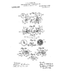
In the drawings in which 'the saxnereference characters' referto the same mechanical. elemcntin all' ofthe figures, Figure lis a top plan-view of the device, some of the concealed partsbein shown in dotted outline;
I Fig; 2 is a side e evation of the parts. with the handle omitted,the casing being shown in fr..trasection Fig. 3 isa1 central vertical sere-n on the plane of the line '3f-3 iuF 1g.
' mechanism sup orting plate; 51s .an-enlarged detail o `the stop bars; F1g. 6 is a de# FigS is aplan View of the parts with the casing removed, `some of the parts being slim- ;n horlzontal sectlon; Flg. 9 is a top L. i View of the rear ends of the key lates 11i taken-directly 'beneath the numeral eels;
.to understand .the construction' "transverse sect-ion o n the 26-26 in'Fig. 27; Fig.- 271s a sidegelevation perspective view of osition When the handle- Fig. 10 is a rear elevation of the' parts shouf-n in Fig. 9; Fig. 11 is a perspective detail, anil Fig. 12 is a perspective detail of the l rc stt-'ni 5 restoring spring. Fig. 13 is adetail pew spective of the multiple non-printing tlc-tent; Fi'g. 14 is aside elevation of theright hand supporting plate and the parts carried ,there-1 on; Fig. 15 is` an enlarged top plan vieu' Vof:
the printing actuating mechanism; Fig. 1Gl
Vis a. lfront elevation.of thel parts shown in Fig. '15; Fig. 17 is a top plan viewl of aracl; and type plate; Fig. 18 1s a transverse. scc.
tion of a 'rack and type plate guide .posten- 'the plane of the line 18-18 inFigv- 22;,Fig.
19 is a detail perspective of a type; Fig-.20.
is a top plan view of the rack and type plate February g4; 190s, serial No. 417,352.1 Divided and this application flied Jaim, l
guide post; Fig. 21 is a side elevation of the upp'er part of the rack and'typc plate guide post; Fig. 22 is a side elevation of the rack and type plate guide post.; Fig. 23 is a side elevation o-f a rack and type plate; Fig
G.- 24 isla rear elevation of the saine; Fig. is an en" larged transverse section ofn .the plane ofthe line 25`25 1n Fig. 23; F1g.'2.6 v1s an enlarged lane ofthe line of the upper part Vof a-rack and type plate,
and Fig. 28 isa front elerationof the parts' shown in Fig. 27 ';"Fig. 29 is a perspective des tail of a type actuator; Fig. 30 is a detail ing mechanism; Fig. 32 `is a rear View ofthe prior to the reversing movement; Fig; is
31 andv32'-; Fig. 36 `is a side elevation of the the numeral' wheel4 lever.; Fig. 31 is a top plan view-of the -ribbonfeed-- 'parts shownin F ig. 31; Fig. 33 a .plan 'View of theribbon feed reversing lever; F ig. 5. '34s isa horizontal central section and partiat top plan'view of the ribbonspoolsand types tro ' a side elevation' of the partsshown in- Figs..
'parte n) :he right. of uw. linges-s6 Ain 31; Fig.;37 isa sideelevation ofthe parts. t0.' the right of theline 37 37 in`Fig'.-31; Figi-i 38 is anenlarged plan. viewn of one'of theff,
paper. platen and'its connected parts; Fig. 39 isa d etailedside. elevation of the bracket .1 213; Fig. 10 is a detail of-thexell o\v '.100;,
Figs. Hand 4:2 are details of the restoring bar elbows; Fig. i3 is a side elevation of the.
, 1153er )late lof the machine andFif. 44 is a front elevation thereof; Fig- 45 is a detailZ of the multiple detent cross sha-ft';Fig46 if.
keyloeking device, and Fig. 48. is'a detail of' 'f 'mounted upon .and within` the 'frainework"v Y eomprising'a base fplatej2 andan outer' up:`
- llfP'Wardlyfv projeti'ng, plates. 4Q adapted to sei-ve.- 'as supports .--for the' keysystem and Avit-lrtwobther sim-ilarplates- 5 and 6to sup-` port otherpartsg` ashereinafter descr-ibedf aperture and also v'tlufol'igh apertures in' theplates registering `-therew ith' and 'a l nu`t 1502 2 engaging Athe end ofthe bolt holds the plates *tions 503 adapted' to engage with' .suitable slotsin the key plates-4 hereinafter-referred to.' Each plate 'Lt'at its. rear' end is rovidedl SO'f-'with transverse guide plate having' right. angled. apertures 8 to perr'n'itoif the passage of the s 'top ,bers 95 hereinaftermentioned;-
- ofi-recessesl to receive thekeystein'sherei j upper key plate '14 'through-which fit passes and; by its 'recess 10, the Bot-torn 'oi this recess d'5 ser-vin' lto limit its-'.'d'own'ward movement'.
At organes-Ch stem 13 isqhmged-ioone -A of alielbow lever `15 pivoted at 16 to the ;-plate 4, the l other endV of VWhieh ".lever is hinged to aA horizontal sto-p bar"9, the rear end of whichpasses through the aperture 8 provided -for that purpose finlthe guide. plate.
duced in cross section ati. the rear of--ashouli der l'and a retracting spring 18 (seej Fig.
"12) is placed' around the end of th'bar .and
between this shoulder 17and thetransverse guide plate' 7,- 'Eachzb'a'r isprovi'dedon'its' uppe edge with-two adjacent notches 19 and 20, on each side of 'a summit 21 bommento vertically susplended in areeess in' the'plateel' arms, an upper arm23 and t on twopara hinged at 28 to a Suitable'bracketg`29-projectf' 111516 adapted toreciproatefili one-of "the U iO o f the plate' ilflmediately'jbe- L neaithit 'andV guided -fby' jan aperture in th-e 'fits stud' 32 on thesarnelatehbar22f When a lower arm 24, pivotedj to At-he plate -4' (seef 'j Fig. 4)L Arearvvard -eirtensiori 26 of` thearm --23 i's hinged to; anupwardlyfprojeeting'j t.'
release-bar 26 pivotedi tofa release leveri27j'-- j ingxf-rom a plate 30 mounted under' 4the up?.- per. partl of the easing. The lever .f2'(^"liasi al y nger piece 3l' jvvithfw'hioh has aSl-Qttd conneetion.
notches l19=Jand 20in the stop: basSand alsof-...2l i with `a retracting spring-33 tending-5to' move.
with; *a tip 41. Hinged et -42 "plate L)His a lever 431 adapte that `the operator begins-. pulling thefmaiiisome other key of the s'aineseries.; -He-,then depress'essuch otherkeyand its stop bart! 7' is moved forward and its'notch 20 engages'f L thesummit 21 is reachedthe s topbar 9 off@ @the-former key, under the influencent" its spring 1 8, isx at once retraetedi vtolitsoriginal *1 position anditslnotoh 19 aA inienga 4es vvitli z e. 4 its stud32f In other worfffanyj-eyfin 115 denominational 'series has -l'eenj depressed; j i .dPIeSSing any otherkeyjjin the sanfieseries, '-1, 35 snot only positions thestop bar'of theseeondkeyin its proper`l` plae'ef but-autoinaticilly and merelyras an in `sidentof:seiddepressiona restores the key first depressed to its original posit-ion. .If an: temhasibeen'enurnerted by the depression of a tnuinbe'r; ff keys'in different series and lit is .t O restore thekey in anyseries, or all the-keys in "thel- -serie's'i'n whieh they-havebeendepressed; tog their original'fpositions andthusetaeef the item, the release leven2Zzinfa-nyseriesjjdei 'sired 'is fshled by 'its ":Iingee piece 31.-' This` moves downwardly-itherod 13o '26 which lifts` the arm 23 ot' the latch bar 22 so that the stud 32 on the latch har which l gaged therefrom and the key is restored to i its original position. Before any numeral key is depressed the parts are in the position shown in Fig. 3. When the' key is depressed, as the engagement of the stud 32 with the summit 21 of the bar 9 occurs, the latch bar 22 is lifted and this raises the stud pin 52 which moves upwardly and elevates the latch arm 49. As the latch arm is raised its notch is raised to permit the notch 38 of the arm 37 to slip under it. This permits the elbow lever 36 to swing on its pivot 35 under the influence of a spring secured to the arm 40 for that purpose. Such movement causes the tip 11 to impinge against the lever 43 and oscillates it on its pivot 42 moving the hook 46 out of the path of a projection on the rack and type plate 81, hereinafter referred to, permitting the latter to rise until such projection contacts with the end of the bar 9, which has been moved rearwardly by the depression of the key referred to.
The accumulating mechanism consists of the numeral wheels and their connections. The numeral wheels are arranged at the rear 1 of-the key system and in the upper part of the casing. Each wheel is provided with a disk 67 having peripheral recesses, a pinion 61, and a cam plate 62, each made integral therewith, or-secured thereto in any suitable manner. 1t is centrally apertured and loosely mounted to revolve on a shaft 63 secured to and projecting laterally from an arm 64 which 1n turn is mounted on a pivot 65 projecting laterally from a sup porting plate 66. Each arm 64 has a tail 53, and at its rear end, is provided with a laterally projecting catch 68 made by bending to one side a portion of the arm itself. A spring 69 exerts a constant inward iension on the arm. Each numeral wheel is arranged Ato display on its periphery the numbers xfrom 1 to 0 in regular order in the manner usual to the art, and it is obvious that there one numeral wheel forv each denominational series of keys.
The supporting plates 66 are arranged 1n Ytransierse series across the machine, each plate having a right angled aperture adapted to receive a bar 71 common to all of the plates and which holds them together and compels them to move in unison. The plates 66 are spaced apart by means of su lementary hars 72 secured to the bars 1 y screws 73. Each plate is apertured to receive a shaft 75 mounted transversely across the machine and terminating in the plates 5 and G. The several plates 66 constitte in etlect a multiple frame supporting the numeral wheel system There are two other plates 70, one mounted al each side of this multiple frame and which are each provided with a square aperture 1o receive the bar T1 and a round aperture to receive the shaft T5. These plates are provided with projecting pins 711, so that when these pins are moved the numeral wheel system is moved as an entirety and oscillates on the shaft 75. The rotation of the numeral wheels is secured by the engagement ot' their pinions 61 with Inova-ble racks 80 provided for that purpose, and the extent of the movement of which in turn is governed by the keys which have been depressed. VThe racks 80 are'cut in the upper front edges of ver-,tical rack and type plates 81, each provided With a Wing 82 which is adapted to carry the types (see Figs. 17, 21 and 23). These wings extend rearwardly and are arN ranged to converge toward each other so that at the printing zone the spaces between them will correspond to that which usually obtains between successive figures of the font to which the types belong. Vertical rods 83 are arranged to serve as guides and supports for the plates 81, each rod resting in a recess formed in a transverse rib 81 at the base of the machine and at its upper end engagingr with the transverse plate 3U. Each plate 81 is provided with two guides 85 serving to cretain the plate in engagement with its rod. The rods 83 are hollow and each contain a spring 85, the lower end of which is secured to a pin 88 passingthrough the guide 86 and plate 81 and the upper end of which is secured in a slit 89 by a pin 90. A vertical slot 58 in the rod permits the movement of the pin 88. Each plate 81 is provided at the lower part of its front edge with a projection 91. and at the lower part of its rear edge with another projection 92, the latter being adapted to engage with the restoring -bar 103 hereinafter described. The spring 86 normally tends lo raise the plate 81 against the force of gravity. The racks 80 consist of teeth ot proper size and shape to engage the pinions 61 of the nu- -meral wheels 60.
95 is the main shaft of the machine mounted in suitable bearings in the base 2 and adapted to be escillated in any suitable nian ner, but preferably' by a handle 96 terminat ingin a gripping member 97 he movement of the mechanism thus far described is accomplished from the main shaft in a manner fully described in -my prior application before referred to. Suitable aprings 122 secured to a rod 123 support from the base of the machineand suitable connections 124 to the main shaft from such springs serve to retract the parts to their initial positions after actuation.
The adding, carrying', totaliziug and resetting operations of the accumulating mechanisin being fully described in my prior application, and forming no part of this invention, will not be specifically described herein.
The printing or recording mechanism will now be described.
Each wing 82 of the rack and type plates 81 serves as a type carrier. Each wing is bent inwardly at 180 and downwardly at 181 see Figs. 24 to 28) and is provided with a removable partition 183 forming a housing for the type. The internal member 180 is .provided with a series of ten round open- -ings 184 to permit of thevpassavepf the type, and the partition 183 is provided with a similar series of ten oblong openings 185 for the same purpose, the two series of openings registering with each other horizontally.
The types 188 each comprise 'a round body 189 which is rovided with grooves 190, a attened shan191 anda head` 192, the latter carrying the fi ure to be printed, (see Fig. 19.) A coile spring 193, one end of which enga es in the groove 190, and the other end o which impinges against the inner side'of the member 180 and surrounds the type body, serves to retract the latter to position after actuation. The openings 185 are made with substantially straight vertical sides and the shanks 191 are flattened to correspond therewith in order to prevent the type from turning.
anged in the rear of and below the` type actuators are a series of triggers 210 loosely mounted on. a transverse shaft 211 and spaced 'apart by collars. Each trigger is provided with a spring 212 the other end of which is secured to a cross rod 199 mounted between brackets 213. Each trigger has an upwardly extending arm 214 terminating in -a roller 215l adapted, t9 engage withv the under surfaceof the corr nding rack and type plate 81, a downward y extending arm 216 terminating in a hook 217 adapted to engage with the catch 205 on the type actuator 200,' andl a projection 218 adaptedy t0 strike against a #ross rod 219 suitably mounted between two supplementary plates 220 and 221 mounted cn and supported from the vshafts 101 and 226. The shaft 211 is mounted between the two arms 102. By this' construction the triggers 210 can cach turn on the shaft 211 but the entire series of: triggers and the shaft 211 are ada ted to oscillate on the shaft-101 as a who Arranged in front of and below the parte justdescribed are energizing elbow` levers 225 each loosely mounted on a cross shaft 226 supported in brackets 227 from the base of the machine andn spaced apart by suitable collars 228. The upper arm 229 of each lever 225 Iis provided with Aa roller 230 adapt- Supposing an item to have been enumerated by the depression of appropriate keys and the stop bars 9 to have been positioned thereby, the main shaft 95 is then oscillated by means of the handle 96 and the restoring bar 103 is lifted in the manner previousl;
described. This allows the appropriate rac and type plates 81 to rise under the inuence of their respective springs and brings into position at the point of print the types corresponding to the keys which have been depressed'. o All of the remaining plates 81, whose keys have not been depressed, rise a slight distance to bring their respective 0 types to the point of print. Each plate; 81 is y similarly positioned at the 0 point whenever the main shaft is actuated. In 'the meantime, as each plate 81 rises Vits trigger 210 follows under the influence of its `spr1 212, its roller 215 remaining in contact witthe loweredge of the plate 81 until the hook 217 engages with the catch 205, when the trigger 210 ceasesto rotate on its shaft 211, and the whole series of such triggers are rotated together on the shaft 101' which movement in turn causesthe actuators 200 to 4swing on their shafts 202 and their recesses 204 to move against the rollers 230 and thus swing the levers 225' against the tension of their springs 232 thereby stretching the latter. As the rotation of each trigger 210 around the shaft 211 continues its projection 218 finally strikes the rod .219 and causes the trigger 210 to swing on its shaft 211 and disengages the hook 217l from the catch 205, whereupon the energizing elbow lever 225 smartly propels the hook 206 of the actuator 200 against the shank 191 of the ty e immediately in front of it.
The ingin mechanism comprises an inkin lribbon w ich is carried upon spools and 'is rought into position in front of the line of print so that the types when propelled forward hstrike. he ribbent.and movbit againstt e recor in paper strip carrie y the platen, as hereignafter described. The
ribbon has a. step by ste -movement from one spool to the other w `xcli movement is reversed automaticaly at the proper time and it has a vertical movement whereby it is i elevated to the and depressed when not so uired.
y, Mpenv'enient places-near, v`- e; nar of the pointof print when required,
machine and` on either side of the printing turned edges sect ion are two ribbon spool spindles 240 and 241 'vertically placed and-loosely mounted in suitable bearings in the base 2, and upper plate 30. Eachnspindle is reduced in cross section at a convenient point to form a liange 242 on which rests a' ribbon spool 243 of usual form. A. tension spring 244 is iuterposedbetween the top of each spool and the plate 30. Near the lower end of each spindle is secured a ratchet disk 245 actuated by a pawl 246, which disk is keyed to the spindle and moves with it. The pawl,
' when reciprocated, rotates the spindle inter# mittently agg-.minst the tension of the spring 244. Centrally placed and rigidly mounted on the shaft 101 is a downwardly projecting arm 248 at the extremity of' which is loosely pivoted a reversing bar 249, provided at each end with a fork 250 (see Figs. 32 and Loosely mounted on the shaft 101 on each side of the arm 248 are two crank arms 251, each prevented from lateral displacement by a pin 252 on the shaft engaging with a slot 253 on each arm. Each crank arm is provided with an inwardly projecting foot 254 having al downwardly projecting pin 255 adapted to engage with the fork 250 of the bar 249. 0n each crank arm 251 is a lateral projecting small shaft 257 on which is loosely mounted the pawl 246 between two inwardly curved bearings 259 permitting a slight lateral movement of the pawl (see Figs. 32, 35 and 36). The pawl 246 is preferably made of a piece of flat metal twisted to bring its outer extremity into a horizon- `tal position and provided with a downwardly projecting tooth 258 adapted to engage with the teeth of the ratchet disk 245, the pawl 246 resting upon and being supported by this disk. A flat spring 256 is secured to the crank arm 251 and is adapted to engage the side of the pawl 264 to holdthe same in engagement with the ratchet disk 245 (see Figs. 31, 35 and 36h). Loosely mounted on one of the small shafts 257, in the machine shown in the drawings the one nearest the spindle 241 is a roller 250 adapted to engage in notches 261 formed in the edge of an arm 262 pivoted to a bracket 263 projecting` from the shaft 101 (See Fig. 37).
A spring 264 secured to the arm 262 and the brackets 263 holds the former under a proper tension. The two pawls 264 are coupled t0- gethcr by a link 265.
v Means are provided for raising the ribbon 54 to bring it to the point of print at thel proper time. On each side of the arm .248 and benvcen it and the cranks 251 are the two brackets 213, previously referred t0,'and
both rigidly secured to the shaft 101,. Pivoicd to and arranged between these brackets is a lifting frame 268 provided at its upper edge. with two ways 269 with outwardly 56 adapted to embrace and guide the ribbon 54 which is wound upon the spools 243. A downward extension 5T of the plate 30 serves as a lateral guide for the rack and type plates 81, and another extension 5t) of the same plate serves as a guide for the upper end of the lifting fra-me 268.
lVhen the main shaft 05 is oscillatcd. a shaft 101 is also oscillated in the manner previously described, and all ot' the parts secured to it of course move with it. Referring to Fig. 31 it will be noted that one of the pawls 246 is in an engaging position with the disk 245 on the spindle 241 while the other pawl 246 is not. engaged with the disk on the spindle 240 because its tooth 258 projects beyond the periphery of' that. disk. Therefore when the shaft 25 is oscillated and the shaft 101 is also oseillated an intermittent movement is given to the disk 245 on the spindle 241 through its pawl and the spool on that spindle is consequently rotated to wind up the ribbon 54 thereon as shown in Fig. 34. The spring 256 keeps the pawl in engagement with its disk. When the ribbon has been fully wound on its spool, the
further rotation of the disk 245 by its pawl 246 is prevented, due to the tensiion of the tightened ribbon. The disk 245 therefore holds the pawl at. the end of one of the forward strokes of the latter and instead of the disk turning as theretofore, the pawl itself does not move at the next backward oscillation of the shaft 101, but remains stationary While the shaft itself turns. When this takes place, the crank 251 carrying the small shaft 257 also remains stationary and the roller 260 on the end of this shaft is disengaged from one of the notches 261 and moves to the other. This moves the crank 251 to its second position with respect to the shaft 101, and through the pin 255 engaging with the fork 250 moves the reversing lever 249 on its pivot. e movement of the crank 251 relative to the shaft 101 has also moved the spring 256 out of Contact with its pawl 246 and no longer tends to hold the tooth of the pawl in engagement with its disk. The oscillation of the reversing lever 249 has, however, moved the other pawl 246 engaging with the disk on the spindle 240 rearwardly to bring its tooth into engagement with said disk and its spring 256 to assistv and maintain said engagement. The further oscillation of the shaft therefore moves the disk on the spindle 240 and winds up the ribbon on the spool on that spindle. The link 265 Vserves to maintain the pawls in vtheir relative positions and to keep one in alternate engagement with its disk.
The purpose of the lifter is to position the ribbon at the point of print each time an item is to be recorded and to remove it out of the way at other times. As above men tioned, the lifter is pivoted to the brackets 213 and is raised and lowered by the shaft 101 at each actuation of the main shaft. The parts are so arranged that the lifter is raised so as to bring the ribbon to the point of print at the eXtreme end of the forward stroke of the handle and after the actuators 200 have been moved forwardly to be in position to strike, so that the types are propelled forward at the instant when the ribbon is in position. As the rearward stroke of' the handle begins the lifter is lowered and the ribbon is thereafter out. of the way until t ic main shaft is again actuated.
The paper carriage is mounted at the rear of the machine on the casing 3 and is provided -with suitable actuating mechanism as fully described in my prior application. The machine is also provided with a repeat key, means for absorbing the shock due to the return movement of the operating handle, means for canceling an item enumerated on theN key board, a non-adding key, means for automatically counting the number of items accumulated. limiting the items to a predetermined number, interrupting such enumeration and automatically locking the numeral wheels when the last item has been enumerated, means for preventing the actuation of the operating handle when the total key is partially depressed and the numeral wheels out of engagement with the racks or preventing the reversal of the handle after it has been partially moved in the proper direction, but these form no part of the present invention and will not be particularly described herein.
The non-printing key comprises a key stem 410 having a finger piece 411 and a notch 412 (see Fig. 14). It is hinged at its lower extremity to one end 0f an elbow 413, the other end of which is pivoted to a lever 414 extending longitudinally of the machine and pivoted -to a cross shaft 415 which is adapted to oscillate a multiple detent 416 mounted between the two brackets 213. This y detent comprises a series of hooks 417 which are so positionedas t9 engage pins 418'pro; jecting laterally from the arms 216 of the triggers 210. It is obvious that when the key 410 is depressed the hooks 417 are oscillated into the paths ofthe pins 418 so as to intercept the triggers and detain them against movement (see Fig. 7). When they ane so prevented from moving, the type actuators are not moved or energized and no printing operation can take place. The function of the printing mechanism is interrupted so long as the key 410 remains` depressed. ll'hen the key 410 is released 1a spring 419 serves to retract it to its original position.
The non-numeral keys, namely the repeat key, the non-adding key, and the non-printing key is each provided with a depending stem having a notch adapted to engage with the edge of the plate 14 for the purpose of holding such keys in position after depression. It is not, however,
always desirable to hold them,
or any of them, depressed during more than one oscillation of the main shaft and it sometimes happens than the operator will inadvertently cause the engagement of the key stem by such notch moving under the plate 14 and thus use the key more than once when actually he desires to use it but oncen In order to avoid this accidental repeated use of such a key,`means are. provided whereby the key cannot be accidentally locked in a depressed position, but must be consciously moved by the operator to 'be so locked and after being so locked must be positively and manually released in order to be restored to its original position. The device referred to is illustrated'in Fig. 47, the repeat key being used for that purpose. In this figure, the key stem is designated 410 and the finger piece 411. There is pivoted` however, to the plate 5 a latch 235 comprising a finger piece 236 and provided with ahook 237 adapted to engage a pin 238 projecting laterally from the key stem. There is also a retracting pin 239. The key stem is slotted at 234 to allow it to pass the pivot 233 of the latch. Vhen the key is depressed its stem 410 is moved downward until it reaches the end of its stroke. If nothing further is done, as soon as the downward pressure, due to the finger of the operator, urally rise under the influence of its retracting spring. If it is to be retained in its depressed position the operator must move the latch 235 so that its hook v237- will engage `with the pin 238. ythe tension of the spring 239 and cannot ac- Y This movement is 'against cidentally take place. 'Vhen it has -taken place the key will be held until it isl manually released. This is accomplished by tapping the finger piece 411 lightly downward, because as soon asthe pin 238 is moved below the plane of the beak of the hook 237, the spring Q39 will pull the hook out of the path ofthe pin 238 and the key will be retracted upwardly by its spring.
It has been explained how at eachactuw# tion of the main shaft the restoring bar 103 is lifted and the rack and type plates 81,001#- lresponding to the denominations in which no key has been depressed, are raised to bring their O types opposite the point of print because the parts are so proportioned that the beak of the hook 46 engages the pro'ection 91 to bring the O`type at the ot er end of the same plate 81 to the properpoint."
It has not ben explained, however, how the zeros are automatically printed. This will now be done.
lower order (provided the latter has not been already engaged by its own trigger 210) and bodily moves the latter to retract its energizer and be propelled toward its type when the trigger -210 of the tirst named actuator is released. Thus the rack and type. plate 8l in each denomination where no key is depressed is automatically moved to bring its 0" type to the point of print and its actuator is automatically energized and propelled forward to print such type. In a similar manner any other actuator of lower order, the rack and type plates of which has been moved to the 0 printing point is actuated by the adjacentactuator of higher order, whether such adjacent actuator lhas been brought to the 0 point or4 to a point to print an integer.
It is to be noted that in the above described fnechanism, the parts are free from complication in construction and mode of operation; their movement is direct and positive and usually in straight lines; they can largely be made of standard material and without elaborate finishing processes;
their operation requires little power, thev key touch is light and the handle action does not induce undue fatigue. There is accomplished in this device everything accomplished in much more complicated machines, and in a more economical way, and the cost of its manufacture and use'is necessarily less.
The carriage mechanism, the paper feed mechanism, the Slidable brackets adapted to support the paper roll and the ribbon feed mechanism above described are, by a` requirement of the Patent Oiiice, removed from this application and will be made the subject of other applications for Letters Patent. ot' the United States.
lVhat l claim as new is:-
1. A. rack and type plate provided with a projectionat a distance from the rack and in substantially the same plane therewith and a second projection on the opposite edge of the rack and substantially in the same plane therewith and a tiange adapted to carry types in a different plane.
-2. In a machine of the character decribed, a. series of type actuators, a corresponding series of energizing levers, springs therefor, one for each lever. means for moving the actuators against the levers to charge their springs, a trigger between the moving means and each actuator regulating such movement ard means for moving the trigger to engage the actuator, comprising a type carrier.
3. In a machine of the character dcscribed, a series of type actuators, a corresponding series oi energizing levers, springs therefor. one for each lever, means tor moving the actuators against the levers to moving means andeach actuator and means for moving the trigger to engage the actu a-x `a type carrier, and means for moving the trigger to discngage it from the actuator, comprising a permanent stop interposed in its path.
5. In a. machine of the character described, a series of type actuators, a corre-v sponding ,series of energizing levers, springs therefor, one for each lever, means for mov ing the actuators aga-inst the levers to charge their springs and a series of triggers moving with said moving means and adapted to engage with and be. disengaged from the type actuators as the moving means move.
G. In a. machine of the character described, type carriersarranged in denominational series, each carrying rcciprating types, means for moving the carriers tobring any type carried thereby to a point of print, type actuators adapted to propel the types after they have been brought tothe point of print and triggers controlling the actuation of the type actuators adapted lo be moved to an actuating position such 1nove ment being controlled b v the type carriers.
7. A series of type carriers. a series of type actuators one for each carrier, means for moving each actuator to energize it. means for releasing it after such energization and devices, one carried by each actuator, adapted when its actuator is moved to move the adjacent. actuator to the right and to hold it until its actuator is released.
8. Two type actuators, one of higher and the other of lower order in denominational relation, each provided with an eaagizing Spring, means for moving the actuator of higher order against the tension of its energizing spring and a device carried bythe actuator of higher order for similarly and automatically moving the actuator otalower order against its spring when it has not otherwise been so moved.
9. Two type actuators, one of higher and the other of lower order in denominational relation, each provided with an energizing spring; means for moving the actuator of higher order against the tension of its energizi 11g spring and a device carried by the actuator of higher order for similarly and automatically moving the actuator of lower charge then-springs, a trigger between thc order against. its` spring when it has not 4p mechanism adapted to print a plurality otherwise been so moved, comprising an army i characters side by side, of a. paper carriage,
on the actuator of higher order projecting over into the plane of the actuator of lower order.
l0. A series of vertically slidable type carriers, a series of pivoted type-actuators, one for each carrier, a series of pivoted triggers, one for each actuator, bearing yieldingly against the under edge of its corresponding normally out of engagement with its actuator, and means normally tending to produce such engagement automatically when an actuator is moved to engagement with i type carrier, means for holding the trigger its corresponding carrier.
11. A series of type actuators arranged in denominational order, means for' moving each one of them independently, an arm on each actuator extending into the plane Aof movement. of its neighboring actuator of vlower order, whereby when any actuator is moved. all of the actuators of lower order are bodily moved.
12.` .i series of type carriers, a series of type actuators, means for n'ioving all of the carriers automatically to a Zero print-ing position and means for moving any otl them to numeral printing position, means for automatically moving the ,type actuator of an carrier moved to a numeral printing position, an arm on each type actuator extending toward the right into the plane of movement of its adjacent actuator whereby when any type carrier is moved beyond a zero printing position the arm on its actuator 'bodily moves all of the type actuators to the right thereof to cooperate with the type carriers at a zero printing position.
13. rlhe combination with the printing oi characters side' by side, of a paper carriage, ,manually movable predetermined distances laterally of the machine but longitudinally of the cairiage` devices for intermittently and automatically moving the carriage and means for intermittently moving the inking ribbon t0 position between the printing mechanism and the carriage in unison with the actuation of both of them.
14. The combination With the printing mechanism adapted to print a plurality oi l l l i l l manually movable predetermined distances laterally of the machine I of the carriage, devices tor intermittently and automatically moving the carriage and means for intermitteiitly moving the inking ribbon to position between the printing mechanism and the carriage in unison with the actuation of both of them and simultaneously movil-.g the ribbon in the direction of its own length.
but longitudinally 15. The combination with the )rintiney 16'. The con'ibination with the printing mechanism adapted to print a'plirralitybi' characters sideby side, of a paper carriage; manually movable predetermined distances laterally of the machine but longitudinally of the carriage, devices for intermittently and automatically moving the carriage and means for intermittently moving the inking ribbon to 'position between the printing' mechanism and the carriage in unison with thtl actuation of both of them, comprising an oscillating shaft, a crank, a lifting trame, and a lateral guide to position the traine when lifted.
1T. A series of type actuators, a series of triggers one for each actuator. means t'oil movingl each trigger separately, vmeans for moving all of the triggers together as a series, a key on a keyboard and means for preventing their movement, including a multiple detent operated by the key. ,y
Titness my hand this 19th day ot' June 1903, at New York. N. Y. l
JASON C. LOT'TE HINI). Vitnesses:
VILLIAM R. BAERD, MAY HUGUES.
Copies of this patent may be obtained for five cents each, by addressing the Commissioner ot Patents.
Priority Applications (1)
| Application Number | Priority Date | Filing Date | Title |
|---|---|---|---|
| US440399A US1069152A (en) | 1908-02-24 | 1908-06-25 | Printing mechanism for adding-machines. |
Applications Claiming Priority (2)
| Application Number | Priority Date | Filing Date | Title |
|---|---|---|---|
| US1908417352A | 1908-02-24 | 1908-02-24 | |
| US440399A US1069152A (en) | 1908-02-24 | 1908-06-25 | Printing mechanism for adding-machines. |
Publications (1)
| Publication Number | Publication Date |
|---|---|
| US1069152A true US1069152A (en) | 1913-08-05 |
Family
ID=3137390
Family Applications (1)
| Application Number | Title | Priority Date | Filing Date |
|---|---|---|---|
| US440399A Expired - Lifetime US1069152A (en) | 1908-02-24 | 1908-06-25 | Printing mechanism for adding-machines. |
Country Status (1)
| Country | Link |
|---|---|
| US (1) | US1069152A (en) |
-
1908
- 1908-06-25 US US440399A patent/US1069152A/en not_active Expired - Lifetime
Similar Documents
| Publication | Publication Date | Title |
|---|---|---|
| US1069152A (en) | Printing mechanism for adding-machines. | |
| US1899444A (en) | Adding and listing machine | |
| US1352070A (en) | Listing-machine | |
| US2677498A (en) | Indexing and escapement mechanism | |
| US267367A (en) | Assig-noe to the hammond type | |
| US559345A (en) | Type writing machine | |
| USRE14185E (en) | Best available cop | |
| US2119003A (en) | Calculating machine | |
| US924066A (en) | Calculating-machine. | |
| US605619A (en) | wentscher | |
| US578303A (en) | wolfe | |
| US1054154A (en) | Adding-machine. | |
| US968674A (en) | Recording calculating-machine. | |
| US1329028A (en) | Listing and adding machine | |
| US1249124A (en) | Adding and recording machine. | |
| US1066455A (en) | Type-writing and computing machine. | |
| US611146A (en) | quentell | |
| US913306A (en) | Key mechanism for typographic machines. | |
| US1396215A (en) | Clear-signal-printing mechanism for listing-machines and the like | |
| US940709A (en) | Adding-machine. | |
| US1203836A (en) | Type-writing machine. | |
| US622470A (en) | hollerith | |
| US1349880A (en) | Check-writer | |
| US524290A (en) | Island | |
| US463859A (en) | Type writing machine |