US1069150A - Sign. - Google Patents
Sign. Download PDFInfo
- Publication number
- US1069150A US1069150A US70300812A US1912703008A US1069150A US 1069150 A US1069150 A US 1069150A US 70300812 A US70300812 A US 70300812A US 1912703008 A US1912703008 A US 1912703008A US 1069150 A US1069150 A US 1069150A
- Authority
- US
- United States
- Prior art keywords
- lamps
- sign
- disk
- segments
- casing
- Prior art date
- Legal status (The legal status is an assumption and is not a legal conclusion. Google has not performed a legal analysis and makes no representation as to the accuracy of the status listed.)
- Expired - Lifetime
Links
Images

Classifications
-
- G—PHYSICS
- G09—EDUCATION; CRYPTOGRAPHY; DISPLAY; ADVERTISING; SEALS
- G09F—DISPLAYING; ADVERTISING; SIGNS; LABELS OR NAME-PLATES; SEALS
- G09F11/00—Indicating arrangements for variable information in which the complete information is permanently attached to a movable support which brings it to the display position
- G09F11/02—Indicating arrangements for variable information in which the complete information is permanently attached to a movable support which brings it to the display position the display elements being secured to rotating members, e.g. drums, spindles
-
- Y—GENERAL TAGGING OF NEW TECHNOLOGICAL DEVELOPMENTS; GENERAL TAGGING OF CROSS-SECTIONAL TECHNOLOGIES SPANNING OVER SEVERAL SECTIONS OF THE IPC; TECHNICAL SUBJECTS COVERED BY FORMER USPC CROSS-REFERENCE ART COLLECTIONS [XRACs] AND DIGESTS
- Y10—TECHNICAL SUBJECTS COVERED BY FORMER USPC
- Y10S—TECHNICAL SUBJECTS COVERED BY FORMER USPC CROSS-REFERENCE ART COLLECTIONS [XRACs] AND DIGESTS
- Y10S362/00—Illumination
- Y10S362/812—Signs
Definitions
- This invention relates to illuminated signs which are rotatable, an electric motor being employed for effecting the rotation of the sign, and the illuminant being a-series of electric lamps.
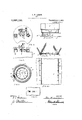
- Figure 1 is a plan view of the sign, partly in section.
- Fig. 2 is an elevation, partly broken away.
- Fig. 3 is a plan view, and
- Fig. 4 is a side elevation of the motor and drive gear.
- Fig. 5 is an elevation, and Fig.
- Fig. 7 is a sectional detail
- Fig. 8 an elevation showing the method of securing the sign panels at the sides.
- Fig. 9 is a plan view of one of the controller segments.
- Fig. 10 is a sectional detail and elevation showing the method of securing the sign panels at the bottom.
- Fig. 11 is an elevation of a fragment of the sign.
- Fig. 12 is a detail view showing one of the brushes of the controller.
- a vertical casing comprising a bottom I on Whichare mounted vertical partition walls A which radiate from a central cylinder B. which is also mounted on the bottom I.
- the casing is provided with a peaked roof or cover E.
- the bottcm I is mounted on a cylindrical case'H resting on a base J.
- To the bottom I is made fast a vertical shaft S which is supported at its lower end in a step-bearing s on the base J, on which latter is also mounted an electric motor K which is connected to the shaft S by a suitable train of reducing gears 7:: as shown in Figs. 3 and 4,
- the case H incloses the motor and drive gears.
- L denotes a disk of insulation which is carried by the under side of the casing bottom I.
- the disk has a central opening Z through which the shaft S loosely passes, said disk being located concentrically with respect to the shaft.
- a collector'ring m which is connected by wires U to the lamps in the respective sections of the casing formed by the partitions A.
- six collector segments M Arranged concentric-ally with respect to the collector ring, on the outside thereof, are six collector segments M which are also connected to the lamps by wires V in the same manner as the ring m.
- the brushes may be made of a piece of clock spring which is fastened at its ends to the plate a, from which latter it extends in the shape of a bow as shown in Fig. 12, the
- single conductor 2 connects the brushes w and m with one side of the current source, and a conductor 3 connects the brush y with the other side of said source.
- the segments M have two portions which are different distances from the center or axis of rotation of the disk L, the two parts being joined by a lateral portion so that their continuity is not interrupted.
- the arrangement of the segments on the disk L is such that each one laps substantially one-half of two adjacent ones, the portion nearest the center lapping the portion of the adjacent segment which is farthest from the center.
- the short lateral parts of the seg ment is between the ends of the two adjacent segments, said ends being spaced therefrom.
- the segments form two. concentric rings having gaps at regular intervals, and each segment extends through an arc of substantially 120.
- the signs, proper, lows An outside pane in the casing. Next to the pane is a sheet of opaque paper or sheet metal which is perforated to form the letters of the sign, as indicated at a". Back of this is placed a sheet cl of any colored paper or glass that is trans parent, and last another pane R of glass is placed in the frame. This last pane of glass is omitted if glass is used in place of paper. The light from the lamps C will shine through the transparent paper or glass and make the letters formed by the perforations 1" in the opaque sheet plainly visible at night, and this combination also produces a very showy effect in the daytime.
- he outer edges of the walls A are rabbeted as indicated at a in Fig. 7 in which rabbets the vertical edges of the sign panels seat and are held by strips 0 fastened to the edges of the walls A by screws P and overlapping the panels a sufiicient distance to hold the same in place.
- the bottom I also has..rabbets forming seats for the bottom are constructed as fol- Q of glass is placed edge of the sign panels and carries retainingstrips T as shown in Fig. 10.
- a'rotatable casing having compartmentasign panels on each compartment, electric lamps mounted in the compartments, means for rotating the casing, and a currentcontroller comprising a disk of insulation mounted on the bottom of the casing, a collector ring carried by the disk and connected to the lamps of the respective compartments, collector segments on the disk connected to the lamps, said, seg ments extending concentrically with respect to the collector ring and having portions which are different distances from the center of the disk, the innermost one of said portions lapping the outer portion of one adjacent segment and the outer portion lapping the innermost portion of another adjacent segment, and brushes in contact with the segments and the collector ring.
- a rotatable casing having compartments, sign panels on each compartment, electric lamps mounted in the compartments, means for rotating the casing, a disk of insulation mounted on the bottom of the casing, a collector ring carried by the disk and connected to the lamps of the respective compartments, collector segments on the disk connected to the lamps, said segments extending concentrically with respect to the collector ring and having portions which are different distances from the center and a current controller comprising of the disk, the innermost one of said por-
Description
J- W. LARSON.
SIGN. APPLICATION FILED JUNE 11 1912.
1,069,150. Patented Aug. 5, 1913.
Z SHEETSBHEET 1.
FOR SFILE.
W C l) flGr/z- H IM H ,1
,f/G-Zr WITNESSES wvswon' .II I don Awe/key.
J. W. LARSON.
SIGN.
' APPLIGATION FILED JUNE 11, 1912. 7 1 069 1 50 Patented Aug. 5, 1913 J 2 SHEETS-SHEET 2.
F/Grfir FIFE SELE F/G./I.- 7A A ZZ':
PATENT- OFFICE.
JOHN W. LARSON, OF GRAND ISLAND, NEBRASKA.
SIG-N.
Specification of Letters Patent.
Patented Aug. 5, 1913.
Application filed June 11,1912. Serial No. 703,008.
To all whom it may concern:
Be it known that I, JOHN W. LARSON, a citizen of the United States, residing at Grand Island, in the county of Hall and State of Nebraska, have invented certain new and useful Improvements in Signs, of which the following is a specification.
This invention relates to illuminated signs which are rotatable, an electric motor being employed for effecting the rotation of the sign, and the illuminant being a-series of electric lamps.
It is the object of the present invention to provide a sign of the kind stated embodying certain novel and improved structural details to be hereinafter described and claimed, and also to provide an improved controller for distributing the electric current to the lamps.
In order that the invention may be better understood, reference is had to the accompanying drawings in which Figure 1 is a plan view of the sign, partly in section. Fig. 2 is an elevation, partly broken away. Fig. 3 is a plan view, and Fig. 4 is a side elevation of the motor and drive gear. Fig. 5 is an elevation, and Fig.
6 a plan view of the current controller. Fig.
7 is a sectional detail, and Fig. 8 an elevation showing the method of securing the sign panels at the sides. Fig. 9 is a plan view of one of the controller segments. Fig. 10 is a sectional detail and elevation showing the method of securing the sign panels at the bottom. Fig. 11 is an elevation of a fragment of the sign. Fig. 12 is a detail view showing one of the brushes of the controller.
The general construction of the apparatus is hexagonal in shape. A vertical casing is shown comprising a bottom I on Whichare mounted vertical partition walls A which radiate from a central cylinder B. which is also mounted on the bottom I. The casing is provided with a peaked roof or cover E. The bottcm I is mounted on a cylindrical case'H resting on a base J. To the bottom I is made fast a vertical shaft S which is supported at its lower end in a step-bearing s on the base J, on which latter is also mounted an electric motor K which is connected to the shaft S by a suitable train of reducing gears 7:: as shown in Figs. 3 and 4,
portion connectingthe two whereby the casing which carries the sign panels is rotated very slowly. The case H incloses the motor and drive gears.
On the cylinder B are mounted incandescent lamps C which are controlled by the device shown in Figs. 5 and 6. Referring specifically to these views, L denotes a disk of insulation which is carried by the under side of the casing bottom I. The disk has a central opening Z through which the shaft S loosely passes, said disk being located concentrically with respect to the shaft. On the bottom of the disk is a collector'ring m which is connected by wires U to the lamps in the respective sections of the casing formed by the partitions A. Arranged concentric-ally with respect to the collector ring, on the outside thereof, are six collector segments M which are also connected to the lamps by wires V in the same manner as the ring m. On the base J are stands W carrying a plate of insulating material ito which are secured brushes w, w and y, the first two being arranged to contact with the segments M and the other one with the ring m. The brushes may be made of a piece of clock spring which is fastened at its ends to the plate a, from which latter it extends in the shape of a bow as shown in Fig. 12, the
bowed portion making the contact. A'
As will be seen in Fig. 6, the segments M have two portions which are different distances from the center or axis of rotation of the disk L, the two parts being joined by a lateral portion so that their continuity is not interrupted. The arrangement of the segments on the disk L is such that each one laps substantially one-half of two adjacent ones, the portion nearest the center lapping the portion of the adjacent segment which is farthest from the center. The short lateral parts of the seg ment is between the ends of the two adjacent segments, said ends being spaced therefrom. By this arrangement the segments form two. concentric rings having gaps at regular intervals, and each segment extends through an arc of substantially 120. As the brushes w and w are in contact with both of the rings formedby the segments, it will be evident that the circuit of the lamps of the respective compartments is closed during one-third of each revolution of the casing carrying the lamps andsigns. The circuit is first closed by the engagement of the brush m with the inner portion of the segment, and before the brush 00 passes off the same, the brush w comes in contact with the outer portion of said segment. The brush a: now passes over to the inner portion of the next segment and closes the circuit of the next set of lamps. The circuit is not broken as the brush w passes to the outer portion of the first segment, this taking place before the brush w leaves the inner portion thereof, in view of which the current is not broken and lamps-therefore burn steady. The circuit is from the conductor 2 through the brushes w and m to the segments M and by the wires 1; to the lamps, and thence by the wires U to the ring at an through the brush y and conductor 3 back to the current source.
The signs, proper, lows: An outside pane in the casing. Next to the pane is a sheet of opaque paper or sheet metal which is perforated to form the letters of the sign, as indicated at a". Back of this is placed a sheet cl of any colored paper or glass that is trans parent, and last another pane R of glass is placed in the frame. This last pane of glass is omitted if glass is used in place of paper. The light from the lamps C will shine through the transparent paper or glass and make the letters formed by the perforations 1" in the opaque sheet plainly visible at night, and this combination also produces a very showy effect in the daytime.
he outer edges of the walls A are rabbeted as indicated at a in Fig. 7 in which rabbets the vertical edges of the sign panels seat and are held by strips 0 fastened to the edges of the walls A by screws P and overlapping the panels a sufiicient distance to hold the same in place. The bottom I also has..rabbets forming seats for the bottom are constructed as fol- Q of glass is placed edge of the sign panels and carries retainingstrips T as shown in Fig. 10.
oeawo Behind the lamps C are reflectorsl) to throw the light onto the sign panels.
I claim:
1. In an illuminated sign, a'rotatable casing having compartmentasign panels on each compartment, electric lamps mounted in the compartments, means for rotating the casing, and a currentcontroller comprising a disk of insulation mounted on the bottom of the casing, a collector ring carried by the disk and connected to the lamps of the respective compartments, collector segments on the disk connected to the lamps, said, seg ments extending concentrically with respect to the collector ring and having portions which are different distances from the center of the disk, the innermost one of said portions lapping the outer portion of one adjacent segment and the outer portion lapping the innermost portion of another adjacent segment, and brushes in contact with the segments and the collector ring.
2. In an illuminated sign, a rotatable casing having compartments, sign panels on each compartment, electric lamps mounted in the compartments, means for rotating the casing, a disk of insulation mounted on the bottom of the casing, a collector ring carried by the disk and connected to the lamps of the respective compartments, collector segments on the disk connected to the lamps, said segments extending concentrically with respect to the collector ring and having portions which are different distances from the center and a current controller comprising of the disk, the innermost one of said por-
Priority Applications (1)
| Application Number | Priority Date | Filing Date | Title |
|---|---|---|---|
| US70300812A US1069150A (en) | 1912-06-11 | 1912-06-11 | Sign. |
Applications Claiming Priority (1)
| Application Number | Priority Date | Filing Date | Title |
|---|---|---|---|
| US70300812A US1069150A (en) | 1912-06-11 | 1912-06-11 | Sign. |
Publications (1)
| Publication Number | Publication Date |
|---|---|
| US1069150A true US1069150A (en) | 1913-08-05 |
Family
ID=3137388
Family Applications (1)
| Application Number | Title | Priority Date | Filing Date |
|---|---|---|---|
| US70300812A Expired - Lifetime US1069150A (en) | 1912-06-11 | 1912-06-11 | Sign. |
Country Status (1)
| Country | Link |
|---|---|
| US (1) | US1069150A (en) |
-
1912
- 1912-06-11 US US70300812A patent/US1069150A/en not_active Expired - Lifetime
Similar Documents
| Publication | Publication Date | Title |
|---|---|---|
| US3408623A (en) | Safety traffic signal light | |
| US1069150A (en) | Sign. | |
| US2082612A (en) | Advertising clock | |
| US1058545A (en) | Annunciator system. | |
| US1719518A (en) | Advertising device | |
| US569764A (en) | Charles l | |
| US1864566A (en) | Multiple recording unit | |
| US1569080A (en) | Lundj | |
| US2223605A (en) | Globe clock | |
| US1124215A (en) | Illuminating and sounding sign or indicator. | |
| US2481780A (en) | Multiple position electrically operated display indicator | |
| US838586A (en) | Electric-car sign and signal. | |
| US1362542A (en) | rogers | |
| US2021954A (en) | Traffic signal | |
| US1987459A (en) | Vehicle signal | |
| US2508680A (en) | Electric sign | |
| US1777110A (en) | Sign advertising apparatus | |
| US1061520A (en) | Advertising and like apparatus. | |
| US1444339A (en) | Automatic illuminated changeable sign | |
| US1054098A (en) | Changeable exhibitor. | |
| US1250143A (en) | Electric sign. | |
| US2071255A (en) | Wind screen | |
| US1988429A (en) | Automotive electric equipment | |
| US1823075A (en) | Advertising apparatus | |
| US1814943A (en) | Controller for electrical signs |