US1069104A - Calculating-machine. - Google Patents
Calculating-machine. Download PDFInfo
- Publication number
- US1069104A US1069104A US64764611A US1911647646A US1069104A US 1069104 A US1069104 A US 1069104A US 64764611 A US64764611 A US 64764611A US 1911647646 A US1911647646 A US 1911647646A US 1069104 A US1069104 A US 1069104A
- Authority
- US
- United States
- Prior art keywords
- detents
- counters
- restoring
- wheels
- lever
- Prior art date
- Legal status (The legal status is an assumption and is not a legal conclusion. Google has not performed a legal analysis and makes no representation as to the accuracy of the status listed.)
- Expired - Lifetime
Links
Images


Classifications
-
- G—PHYSICS
- G06—COMPUTING OR CALCULATING; COUNTING
- G06C—DIGITAL COMPUTERS IN WHICH ALL THE COMPUTATION IS EFFECTED MECHANICALLY
- G06C7/00—Input mechanisms
- G06C7/02—Keyboards
- G06C7/06—Keyboards with one set of keys for each denomination
Definitions
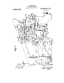
- This invention relates to calculating machines. alul'more particularly. to improve- 1. merits in means to'prevent the over-rotation of the registeisthereof.
- the adding operation is stops in the paths of register driving devices.
- the initial stroke of the main shaft releases. the resigt er-d riving devices which are automatically propelled against said stops.
- the stopsflhe registers ornumeral wheels and driving means are connected, and upon the return or reverse stroke of theshaft-,-restoring means contact with the' 'rcgiste'r-f driving devices toreturnthem'to initial p'o-' siticn.
- Over -'rotation preventing devices have generally taken the form of detents engaging ratchets, or their equivalents,
- One objectof the present invention is to enable the- Over-rotation .preventers to act more quickly both in releasing the adding wheels and in rengaging therewith.
- Another object of the invention is toenable the over-rotation-preventing detcnts in be more-speedily ⁇ vithd rawn from thewheels 1'6 when a total is to be taken toobviate any; possibility of contact when the wheels are in motion.
- Figure-1 is a side view of one embodiment-of the in- 'vention applied".
- the device' being inmor- 8Q finial or idle-position; with parts brokenah ay.
- Fig.2 is a similar-ii view showing the parts in 'the positions occupied when ther'manr shaft "is .at the end of ts initial stroke, an
- Fig. .3 is a View similar to Fig. 1, but-with the total or clearing keydepressedr "Fig. 4 shows the position of the parts. when showing the positions ofjthe trigger rolls 10f) when supporting therocking levers, and" when tripped.
- Fig. 7 is'adetail of the overrOt-atiOn-preventing detents and their carrier.
- Fig 9 is a detail of one transfer mechanism, showing it tripped and about to turn the numeral wheel. Fig. 9-shows the transferunechanism at, thecompletion of the carrying Operation prior tobeing reset.
- machines of the fkey-set type include. generally, a key-section, and a reg v istcr-sawrtmn.
- the key-section comprises s'cvcral laws-arranged inrows or banks't'o form a selective. key board. Depression of any of the keys, as 1,- rocks a lever 2 to pro-' ject. a stop 3. Fig. 5.)
- the register mechanism includes :rack
- Said rack bars are pivoted on front and rear arms 5 and 6 and are driven againstthe stops by springs 7 connected respectively to the rear arms 6- andto a. rod or bail 8,
- the numeral wheels" turn'on ⁇ an-axle 20 (Fig. 2) mounted'i'n arms 21 piyoted-at 22 t0 -the side frames 10, and'a're'normally'held out of engagementwith .the racks by lifting props 23-pivoted to the arms-21 at- 24, said props being slotted as -at 23", andresting on a rod (Figs. 1 and5) carried by swinging arms; 26 .turning on a shaft-27 journaled in the side frames. Links 28- join the-rod preferably to-cranks 29 on the main shaft.
- the main shaft L1 is preferably etfected by a'retunringspring 35; (F connected by a crank 36 to said shaft.
- the bail 8 On such returnst'roke, the bail 8,,- oontrolling the. rack-"bars, first swings to res to re thejattento initialosition.
- sprmgs37 may. beemployed to draw them into' alinementwit-h their-rests 32.- In prac- .tio'e,- a-sl'ight'elear'ance is left between said.
- efleet a carry -f rom--one to another :of tli'fwheels preferably comprisesa. rocker 38 (Figs. 6, 8, and 9) f0r each wheel, said rockers being,
- Said lei-'ers are connected by a resettin bar 54'playing in slots- 55 in resetting lin pivoted to the rear arms of the rockers 38.
- the rear arms 6 supporting the racks 4 maybe connected to a printing section (not shown) and when it is desired to take a total. if such printing section is present, and to clear the machine, a total key 60 isdepressed (Fig. 3) to rock a bent or setting lerertil fast on the rock shaft 27, on oneside of the machine. Through said rock shaft a similar bent or setting lever ,61 on the opposite side of the machine is op erated. Arms 62, 62 on said setting levers jareconnectedby links 63 to the legs or supports 30 of the numeral wheels, said links having slots ti t therein fitting over pins 65 in said supports topermit the latter locks the a are :being lifted to.
- the setting levers carry restoring studs operation of the total key, prior to turning vthe main shaft, said studs clear latches (v8 piv'oted at 69 to angular or restoring levers 70 pivoted to the side frames, at 71.
- Said latches are normally held idle'by rests 72- on the props 23, but the easing down of the props during the initial stroke of the main shaft in taking a total or clearing the machine permits the latches to swing into alinement with the studs 67.
- the total key in the pres -at instance, instead of being released is held in its operated position during: the return stroke of the main shaft, thereby prerentu'ig the release of the numeral wheels from their driving means.
- to'their engagement with terference may be sufiicient toadvance or revc se them one or more steps, Alsoowing ment of the dtivinge-means and wheels, if not prior thereto. This is especially de sirable wherever the wheels move relatively to the drivingmeans to prevcntiover-rotai pivoted at'86 toene of thep inent by the SpringSO;
- tents 76 mounted on a carrier or plate Nextending across the machin'ein front of the numeral wheels 18, t -he"teeth;78 of-which detents el-igage the ratchetornotehed wheels 80 -11 to arrest the latter and their respeotive numeral wheels.
- whiolr srrest occurs before the drive shaft has completed its initiah stroke, and after such arrest,j;the end of the. arm 84 t-rar'elsidly in the slot 83- to permit the. completion of: saidj i nitiil" stroke.
- the carrierin 'shiftirigjdi'xiatitiye position contacts a. restoringlever 88 ;lying in its path of movenientand-pivoted atiSt), and presses itidly forward.
- the adjusting plate 94 is. pressed against the. tappet'and yields to permit the restoring lever 38 to rock out'o'i the Said lei-er may There cussed, as at. 93, opposite the tappet, which i'Ht'SS is normally closed to the 'tap'petby saitladjusting plattglbn't which fits over the tappet when the leveris rocked to idle posi- 'tion'.
- the link and its arm 84' are mm'vd forwardly by the prop and the spring 30 withdraws the detenlsfroni ouga jt-nu-nt with the rogistersarul swings the carrier against the stop S7 without obstruction by the restoring lever.
- the selting'loror fit is returned toward normal position by its spring 73, thereby trillnlrmving the dog J from engagen'unt with the restoring lever as to enable said lever to be operated by the the aunt of-which car-' justing plate94r pivoted'at- 9a'itothfe le erected bevona the edge'oftlie stop 97.:irrests'the tappet uring the return stroke of the desirable, however, that the detents be retively to the. do until thede'tents have been turned to effective position prior to the restoration of the register to' idle position, just as inthe accumulating operation.
- the restoring lever must be released from the dog prior to the comple: tion of the return stroke of the 'main shaft.
- the :detents are quickly disengaged from the wheels, so as not to be struck thereb avhen; the latter drop into' engagementwit the racks, 4, ,as in the totaling or clearing operation.
- The'arm 84 is'providedwith a releasing link -98 preferably riding ona guide 99'and having a cam slot carried by the dog 90.
- the releasing link 98 is drawn forwardly by the arm84, the'cam slot moving idl'yrela- 100 in whichkfits a roll or projection 101.
- na calculating'machine the combina--. .tion with countersdnv ng means therefor, mechanism to effect the engagement and (llS- engagement of the counters and their driving means, and a rockingdrive shaft, of detents for said counters, mca-nstending to shift 'said-fdetents to idle position,restoring;v means to return said detents,:nid means in-? dependent thej restoring means to look said detents in nornial effective position on th? ireturn stroke-of the driveshafti 3.
- the .rombination with counters, and'drlving i'ncans therefor, of detents for said counters means to shift said detents to idle position.
- a lock to hold said detents effective means to ⁇ cleanse the lock,restoring' means to return the detents to effective position, and means to silence said restoring-means prior to the shifting of the detentsto'idle position.
- restoring -means to' return the detents means to shift the restoring mean's to andTh-olditin' lposition prior tothe operation 'off thefina l e; and inan's to release the restoring-means for operation;
- a shit-table carrier several iletents connected therewith, to hold tlnetounters arm-inst turning', a spring normally tendingit'a shift the carrier to withdraw the detents'f'rom eli'eetive position relatively to the counters.
- the wheels an their driving means, of a shift-able oarrier, detents loosely mounted on said carrier. for independent movement relativelythereto, and normally holding the counters against over-rotation; means a) shift the carrier to .move the detentsiuto and out of effective position; a. lock to'main- "tain the detents effective; and vibratory.
- detents to arrest the ,counters means tending to release the detents from the counters, a lock normally maintaining thedetents etl'ective,.means to free the detents froin 'the lock, and a restoring lever, operated by the drive-restoring mechanism to return the detents. 17.
- thecombination with counters, driving; racks-therefor, means to drive the racks in one direction, mechanism controllingthe engagement and disengagement of the counters and racks, rack-restoring mechanismfia key to influence the controlling mechanism through which the engagement, and disengagement ofthe'counters and racks is effected, when taking a total or sub-total, or 'when clearing j-the-machine; and shiftable, over-rotationjpreventing detents for the counters, of a loclc operable vby said control mechanism to normall y ,maintain the 'detents effective; 4 and a restoring device operated bythe rackrestoring mechanism,'to return the detents, and shiftable out of the path of the detents' by'the operation of said hey.
- a calculatingmachine 'the combi nation with counters,- driving means, mechanism to effect-the engagement and disengagement of'the counters and-their driving means, detents to prevent over-rotation of the counters, and means tending to shift said detents 'to inactive position, of a restoring device to return said detents, a driver. to opverate saiddevice, an adjusting plate on said device in the-path "(if the driver, a key-coir. trolled lever, and a dog-on said last-named lever to shift the restoring device 'to idle position, said adjusting-Mate arranged-to yield to enable the restoring device to clear the driver when shifted by the dog.
- the coinbi-. nation with counters; driving means there' for, movable from and toward -initial.position, and normally disen aged from the counters; mechanism toeh ect the engagement and disengagement of the counters and driving means; a key-controlled means connected; to said mechan sm, to vary thev time and duration of such engagement relativelyto the. initial and return strokes of the driving menas detents to lock thecounters against rotation; and means to shift the i detent-s to idle position, operating in' timed relation-to. the driving.
- key controlled lever having a dog to 'throw the 'restoring member to, and hold. it,in idle position; and meansncontrolled by said mechanism to release the dog and: free the restoring member.
- key-controlled lever having a dog to throw 'the restoring'member to, and-hold it in idle" ition; a projection on the dog, a releasing inl; operated by said first-named mechanism 7 and having a. slot therein entered by the projectiomand a cam on the wall of the slott contact the projection on the dog to release the restoring member.
- the combine tion with several individually rotatable counters means to turn the same; and car rying mechanism including rockers, to trans;
- lever 88 contaeting;said-carrier. to return the detents to -.effectiye ;position, a 'tappet 15 ,toqperate therrestorir grlever; a
- mechanism to free therestormg zlevert A calculating machine, having a vi: bratorymainshaft, counters rotated-by suitable driving. means,- theoyer-rotation of said counters being prevented by detents -nor nia-lly held in effective position. by a suitable lock .which, when the machine. isioperated is disabled, to permit, the detenf's-.-to be shifted vto ineffective ,position said rdetents being returned after the. add ng, operation is completed by arestoring lever which may .be
- Iiia calculatingmachine the combination with register members, drive-members therefor, file drive and register mem- .bers adapted for engagement and disen-' gageinent; a main dr1veshaft; and clearmg mechanism to vary .thetime of engage- .ment and disengagement .of the drive and r egist ermembers; of an over-rotation preventer .shi-ftable into and out of effective position relatively to the register -members a restoring:- lever normally lying in the pa.th of the over rotati'on preventer to return the latter to effective position; and .disablin'gemfihanism controlled by the clear- ;ingmechanism,- to displacel the restoring ,Ieveripriorto the operation of the main drive shaa.
- an over-rotation prevent-er shiftable into and out'of effective position relatively to the/register members"; a restoring lever-to return the over-rotationpreventer to effective position, and normally lying in the path Of said over-rotation prevente'r; disbers adapted for" engagement and disen”" abling'meanslcontrolled the suhQtotaling means prior" to the disengagement of the mechanism, to displ'aeeth'e restoring-lever drive and register members.
- gagement' gagement'; and sub-tots.
- ing'mechanismtoprevente'r is antomatically shifted to inef- Y vary the time of engagement and disen--- ect-ive os1tion-,assoonasal0ck, which norgagement of the drive and register mem+ 'm'ally 'oids it efifective, is released, said bers'; of an over 'rotation preventer shiftover-rotation-preventer being retnrned-to ef-' ablegintofand out of effective .positio'nf fective position by a "restoring member 4 0 relatively to theregister members; a lock operable prior to the lock, and normally to holdasiaid over-rotation preventer eflec lying in the path oftheovefirotationprey engagement of the drive and registervmemdisplaced when the caleula'tingimechanism hers; a restoring
Landscapes
- Engineering & Computer Science (AREA)
- Physics & Mathematics (AREA)
- Computer Hardware Design (AREA)
- Computing Systems (AREA)
- General Physics & Mathematics (AREA)
- Theoretical Computer Science (AREA)
- Transmission Devices (AREA)
Description
F. .H. BIGKPORU. CALCULATING MACHINE. APPLICATION FILED SEPT.5, 1911.
Patented Aug. 5, 1913.
7 SHEET$SHBET 1 IN l/EIV TOR F. H. BIGKFORD. CALCULATING MACHINE. APPLICATION FILED SEPT. 5, 1911.
Patented Aug. 5, 1913.
'7 SHEETS-SHEET 2.
m 8 w w W F. H. BIGKFORD. -CALCULATING MACHINE.
APPLICATION FILED SEPT. 5, 1911.
Patented Aug. 5, 1913.
7 SHEETS'SHEET 3.
4 TTORNEY F. H. BICKFORD.
- CALCULATING MACHINE. APPLICATION FILED SEPT. 5, 1911.
Patnted Aug. 5, 1913.
'7 SHBETSSHEET 4.
KMJKMM WITNESSES.-
I. HfBICKFORD. CALCULATING MACHINE; APPLICATION FILED SEPT.5, 1911.
Patented Aug. 5, 1913. I
7 SHEETS-SHEET 5.
WITNESSES: INVENTOR F. H. BICKFORD.
CALCULATING MACHINE.
APPLICATION FILED SEPT. 5, 1911.
Patented Aug. 5, 1913.
WITNESSES:
'Arro EV F. H. BIGKFORD.
CALCULATING MACHINE. APPLICATION 1111111) SEP'I.5, 1911.v
Patented Aug. 5,1913.
7 SHEETS-SHEET 7.
WITNESSES:
"U N lTED STATES PATENT OFFICE.
rnaN n. mcxronn, OF MUNCIE, INDIANA, AssIGNoe TO THE amuseii/mounts COMPANY. OF WILKES-BARBIE, PENNSYLVANIA. A CORPORATION OF PENNSYL- VANIA.
CALCUL ATING-MAQHINE.
Specification of Letters Patent.
Patented Alt 5, 1913.
Application tiled September 5. 1911. Serial No. 641 646.
'1 all 110/mm if m 111 concern lc it known that I. FRANK a citizen of the United States. residing at Mum-iv. Delaware county, Indiana, have in- 5 vented new and useful Improvements in (alculathie-Machines, of which the .followin is a specification. l
This invention relates to calculating machines. alul'more particularly. to improve- 1. merits in means to'prevent the over-rotation of the registeisthereof.
In the well-known \Vales calciilatiugauachine. ineonnection with which this invention is illustrated, the adding operation is stops in the paths of register driving devices. The initial stroke of the main shaft releases. the resigt er-d riving devices which are automatically propelled against said stops. After the arrest. of theregister-d riving devices by said stopsflhe registers ornumeral wheels and driving meansare connected, and upon the return or reverse stroke of theshaft-,-restoring means contact with the' 'rcgiste'r-f driving devices toreturnthem'to initial p'o-' siticn. During such return; said devices-rotate-the wheels to cause the lattertoregister:
the amount indicated by the values of the depressed keys, after which the wheels and tlfeir driving means are disconnected. Car vying mechanisms to transfer from one wheel to another are also provided, the carvying action taking place after the addin'g or registering operation.
vent over-rotationof the numeral wheels, (due to acquired momentum), at the time of disengagementof the driving devices there-;
'from. such wheel-arresting means being especially desirable when the machine is operated rapidly. Over -'rotation preventing devices have generally taken the form of detents engaging ratchets, or their equivalents,
said ratchets being fixed to turn witlrthe" numeral wheels. p
One objectof the present invention is to enable the- Over-rotation .preventers to act more quickly both in releasing the adding wheels and in rengaging therewith.
'To take a total .of the amount registered on the Tales: machine, or toclear the ma- 1 jchine, a. key controlling the time of conuec tion and disconnection of the numeralwheels or counters and their driving means, is opcrated to effect such c nnection prior to the H; Bun: Font),
started by depressing keys which interpose- 'It is customary to provide means to pre-- propulsion of the driving means, and at the beginning of the initial stroke of 'thcma-in shaft, so that, when the driving means are released, they will turn the wheelsiintil the latter are arrested by the contact o'f' stops 50 thereon with checks shiftable-intdthe path of the stopsby the operation-of the key.
The wheelsand their drivingrmeans are dis engaged at the beginning of the returnstroke of the-mam shaft. after which the 65... driving means are restored to initialqposl-= tion', leaving the register clcared, or-at :mro:
Another object of the invention is toenable the over-rotation-preventing detcnts in be more-speedily \vithd rawn from thewheels 1'6 when a total is to be taken toobviate any; possibility of contact when the wheels are in motion. Other objects and advantages will'hereinafter appear and be more fully-pointed out 5- in the claims.
In the accompanying, drawings Figure-1 is a side view of one embodiment-of the in- 'vention applied". to the well-known Yales y .l l calculating machine, the device'being inmor- 8Q finial or idle-position; with parts brokenah ay.
Fig.2 is a similar-ii view showing the parts in 'the positions occupied when ther'manr shaft "is .at the end of ts initial stroke, an
'the-:ordim iry accumulating or adding-opcr- 35 ation. Fig. .3 is a View similar to Fig. 1, but-with the total or clearing keydepressedr "Fig. 4 shows the position of the parts. when showing the positions ofjthe trigger rolls 10f) when supporting therocking levers, and" when tripped. Fig. 7 is'adetail of the overrOt-atiOn-preventing detents and their carrier. Fig 9 is a detail of one transfer mechanism, showing it tripped and about to turn the numeral wheel. Fig. 9-shows the transferunechanism at, thecompletion of the carrying Operation prior tobeing reset.
Although the invention is shown in'conuection with a Wales calculating machine,
its use is not confined thereto or even to key-set machines Adding machines of the fkey-set type .include. generally, a key-section, and a reg v istcr-sawrtmn. The key-section comprises s'cvcral laws-arranged inrows or banks't'o form a selective. key board. Depression of any of the keys, as 1,- rocks a lever 2 to pro-' ject. a stop 3. Fig. 5.) There: are as many stops 3 as. there are keys, the stops' controlled by. each bank or series of-keys, being ar- 1a nged in.a row, one stop only being shown.
.The register mechanism includes :rack
. l ns 4 to cooperate with each row of stops.
Said rack bars are pivoted on front and rear arms 5 and 6 and are driven againstthe stops by springs 7 connected respectively to the rear arms 6- andto a. rod or bail 8,
carried by a rock shaft 9-journaled in the side frames 10 of theanachine; Said rod 8 lies in the paths of theforward arms 5 to normally restrain" the latter and-therack bars against the action of the springs: An
- oscillatory main driversliaft' 11 turns the the springs a-nd on its return stroke, presses, 'said rod..-against the arms t0 return the shaft'may rock shaft -9;' by an arm ing a ro'lll3ufitting in a cam slot 14. formed in a crank 15 fixed to the rock shaft. Said:
main shaft onQits initial stroke, withdraws said bailtofree the ban. 4E-to the action of bars to rest. The main-drive tiirn'ed by a handle 16. I
- Racks 17 (Fig. 5. on i sane -t,-turn' A numeral wheels '18 or flcounters'tl'irough pin.-
up on thekey-board, and toreturn said wheels to zero when the ma'chine is cleared.
The numeral wheels" turn'on {an-axle 20 (Fig. 2) mounted'i'n arms 21 piyoted-at 22 t0 -the side frames 10, and'a're'normally'held out of engagementwith .the racks by lifting props 23-pivoted to the arms-21 at- 24, said props being slotted as -at 23", andresting on a rod (Figs. 1 and5) carried by swinging arms; 26 .turning on a shaft-27 journaled in the side frames. Links 28- join the-rod preferably to-cranks 29 on the main shaft. I 1 a In the adding operation, the desired keys having been operated to .set the correspond-- ing stops 3,, the' main drive shaft is turned on itsinitizil stroke and immediately draws the rod 25 fdrwhrdlyalong a descending are. therebyswinging the props 93 -to lower the numeral wheels to ctfect the en gement of the pi'nions with the racks; S11 engagement, howeyer,.is .deferred .by legs or sup,- ports 30 pivbtally connected to the axle 20 and seating on rests 321m the'side frames. lVhile the props are being drawn forwardly from their supporting positions the arm 12 turning with the drive shaft is idly travers- .been projccted. During the advance of the racks,-t-he rod 25 continues to swing said -props 23, andas' the main shaft neais the g L 12 (Figs. land 2)- fixed to turn-{withthe drive shaft and have sure the return of the supports 30.
ing the cam slot 14- in the crank" 15. but when the main shaft has part-inllycumpicied its stroke, the arm 12 contacts the cam su rface 14 of the slot to turnrock shaft 5) and withdraw the rack-'reslm-ining rod 3 from the'front arms 55 whgreupop the rack-bais 4 are propelled by the springs 7 against said stops 3. Suitable means, not shown; arrestthose racks into whose paths no stops. have limit offits initial stroke after the rack-ba is have beeniarmsted by-their stops, said ro'd contacts the outer ends of.slots 33in tripping links connected to the respective legs or supports30 topull the latter off their rests 32, (Fig.2),whereupon the arms 21 and the numeral wheels drop toengage the pin"- ions 19 with the racks 17, which have been positioned .by the' stops 3.'
'TheuIet u'rn stroke-10f the main shaft L1 is preferably etfected by a'retunringspring 35; (F connected by a crank 36 to said shaft. On such returnst'roke, the bail 8,,- oontrolling the. rack-"bars, first swings to res to re thejattento initialosition. Dnr-f =ing= such restoration the rac turnfthe nu:
meral wheels to caizse them to displaythe correct amount at the completion ofthe operation. j w During the-return of the racks, the trip. rod 25 is being -restored,"and-after said racks have reached theirpositions of. rest,.the nod,
contacts the. Kipper end of the 'slots-23 10f *thepropsto lifti-the wheels and with them the numeral wheels, to disenga e the latter from the racks '(Fig; 1). Tie :nuineral.
wheel supports 30 are likewise lifted, and
sprmgs37 may. beemployed to draw them into' alinementwit-h their-rests 32.- In prac- .tio'e,- a-sl'ight'elear'ance is left between said.
supportsand their rests when the parts are idle, to avoid niceties of adjustment and in- The transferring mechanism. to efleet a carry -f rom--one to another :of tli'fwheels, preferably comprisesa. rocker 38 (Figs. 6, 8, and 9) f0r each wheel, said rockers being,
.mounted on a 0mm bar ilfiexteiiding. be-
tween the side frames- A carrying pawl 40, pivoted "on the rear armrof each rocker;
engages a ratchet 41 fast with the numeral wheel to turn the latter. ,A-sprin}; 42 tends .to tilt the rocker to effect said-engagement,
hand whee is turned past the point at which the figure 9 is displayed, a cam 4:8, turning; with said wheel,
' triggeragainst the tensionof its spring to force the rest from beneath the catch (Fig.- -8)i"-3 This frees thespring 42, \VllKll therebrings the carrying'pawl 40 into en-v (Fig. 9) on the rocker which engages the ratchet when the carrying pawl has turned its wheel one step. This carrying operation occurs as the wheels idle position after disengagement from the racks, the adding operation having been comp'letedl The carrying; mechan sm is faces 51 into seats :38
reset on the next initial stroke of the main shaft by the swinging 'rod 25 (Figs; 2 and 5) or by antifriction rolls =50'thereon, riding over cam faces 51 formed on"-rocki ng levers pivoted on cross bar 53- in the frame.
Said lei-'ers are connected by a resettin bar 54'playing in slots- 55 in resetting lin pivoted to the rear arms of the rockers 38.
The downward swing of the rod 25 (Fi 2) depresses said roe-king levers against t e tension of springs 57, to press the resetting 'rod 54 against the'lower ends of'thegslots links, thereby tilting the 55 in the resetting tripped rockers 38 rearwardly against) the tension of the springs 42 and raising thein forward ends, so'thatthe catches 43 clear the rests 44. The triggers are thereupon restored by springs 47 tointerpose the rests 44 beneath the catcheson -the forward'arms -of rockers 38 and upon the completion of a full forward and rearward stroke of the main shafh'the =rolls 50 ride off the cam (Figs. 2 and 4) in the resetting levers 52 to relieve the tension on the springs 57 which raisethe resetting levers to free the links 56;. The carrying springs catches 0t the-rockers against their rests 44; A stop =39 arrests the trigger in reset position against the tension ofits resetting spring 4-7. p
'The rear arms 6 supporting the racks 4 maybe connected to a printing section (not shown) and when it is desired to take a total. if such printing section is present, and to clear the machine, a total key 60 isdepressed (Fig. 3) to rock a bent or setting lerertil fast on the rock shaft 27, on oneside of the machine. Through said rock shaft a similar bent or setting lever ,61 on the opposite side of the machine is op erated. Arms 62, 62 on said setting levers jareconnectedby links 63 to the legs or supports 30 of the numeral wheels, said links having slots ti t therein fitting over pins 65 in said supports topermit the latter locks the a are :being lifted to.
e7, (Fig. and
42 then press theforward arms orto swing relatively to the total key mochanism, in the ordinary accumulating operations just (lescribed. \Vhen the setting levers are rocked, they operate through-said links to displace the supports rela-ti\el to their rests 32 to. prevent delay in the engagement of the register wheels and their drivin means when the lifting props are trippe so that the numeral wheels drop into their racks' at the beginning of the. initial stroke of the main-shaft as the props 23 are eased downwardly, by the swinging rod 25, and by the time the free endof the arm 12 has traversed the idle portion of the cam slot 14',-the wheels have been engaged with their driving means in 'readiness to be turned when-the racks are released by the'rest I spring-pressed racks during their-forward movement-oir'the initial stroke of the 'main shaItIand-in adirection reverse to-the adding'o'r accumulating rotation of the wheels), untilyarrestedby -the contact of stops on wheels (which stops .maybe combined with'thecams 48 shown) withchec ks 66 5) swunginto the paths .of the stops by the operation ofthegtotal key through suitable vand 'well known Wales mechanism (not shown). At such time the wheels all display. zeros at the reading line.
To release the numeral wheels from their driving means at the completion ofthe totalng operation, so as to leave the machine clear, the setting levers carry restoring studs operation of the total key, prior to turning vthe main shaft, said studs clear latches (v8 piv'oted at 69 to angular or restoring levers 70 pivoted to the side frames, at 71. Said latches are normally held idle'by rests 72- on the props 23, but the easing down of the props during the initial stroke of the main shaft in taking a total or clearing the machine permits the latches to swing into alinement with the studs 67. When the main shaftreaches the end of its initial stroke, the total keys and their setting lovers are freed to Lthe action of springs 7 3, and at the outset of the return-stroke of the shaft, said setting levers 61,: 61' are rocked to press the restoring studs 67 against the latches 68 and thereby upwardly against pins 74: on the legs or suppcrts30 to numeral wheels from the driving means before said driving means is started on its I bail or, rod .8. The numeral wheelsare thus turned by the rock the angular levers 70 to cause their arms 71to press lift the latter and disengage the when rocked by-the initial return, by the'restoring bail or 2rod8. As
soon as the lower ends of the clear the rests 32, springs 37 snap the sup ports on to the rests which then ho ldt.he wheels in idle position until the tripping rod 25 returns the Drops 23.
In taking a-suh total, that is, printing an supports 30 -55 the driving means,-a slight contact or inamount disclosed by the register and retaining, said amount on the wheels, the total key, in the pres -at instance, instead of being released is held in its operated position during: the return stroke of the main shaft, thereby prerentu'ig the release of the numeral wheels from their driving means. As
. a 'resul t,'.tlie numeral wheels. remain in engagement "with their driving means during the .return "stroke of the .main "shaft, and
.after being; revelsely rotated, during the forwardly on the-return stroke of the main initial stroke of the main'sha ft, as explained in the operation of taking, a total, are turned shaft to again disclose, the amount registered at the beginning of the sub-totahng operation. As the main shaft approaches "the adding or accumulating operation, the
the end of its. return stroke, after-having l e'stored' the rack bars, the numeral wheels are released from said rack bars by the lip-- ward travel of the tripping rod -25, as in total-key being; restored to idle position at the end of's'uch return stroke.
wheels'l normally hold' the numeral wheels.
' jpartsno'w -tobe described.
Locking pawls' 75 engaging .the ratchet age; staccidentalfturning when the latter" are'in idle or raised. position. 1
1 The foregoing construction is old, and only. constitutes part of the, present inven .tion,-so far-as it is combined with the new 'hen the: naehine 1S- rapidly operated through thefloseillatioii' of the main drive amounts.
shaft 11, either by; the handle or by .a motor,-
the numeral wheels are turned at -high-sped and acquire considerable momentu nfwhie'h tends'to carry thewheels' past theirproper positions when disengaged from their driV- ing means, and thus. register inaccurate:
' .To obviate this disadvantage,
lover-rotation'preventers in the form of de tents toengage the ratchet wheels ll-have commonly been 'provided.' It has been.
found,- -however,.tha tin order to accomin'o date the detents 'to the. varying operations I of theniime'ral wheels, the detent's must" be quickly released'from the ratchet wheels so as not to interfere with themovements of said wheels, either when the latter areshift- -*inginto engagement with their driving means or when turning. This is necess girybecause said .wheels are .veryeasily turned 4 to themomentum referred to, it is advisable that the detents engage the rat-chets not later than at the moment of thetdlsengagel on the axle and 'when freed from the locking pawls and prior. to'their engagement with terference may be sufiicient toadvance or revc se them one or more steps, Alsoowing ment of the dtivinge-means and wheels, if not prior thereto. This is especially de sirable wherever the wheels move relatively to the drivingmeans to prevcntiover-rotai pivoted at'86 toene of thep inent by the SpringSO;
through i t the carrier-T end its action of the spring. whioh sw'lngs the;
As one means to permitthe carrier'tobe shifted from and toward the numeral-wheels to. release the detents therefrom when}- the" 5 register-is to beoperatem or'to enghge-jthem-j therewith to preventoverfretatiomfsaid.caf-J hefip site sidefframesand shidfletht's. normally held aetiveagainistflthe .tension 'ggjfia590:
prising abar 'orcoujple L the ,ca'rrieria'nd eoriiiect g pin and slot 83- toi-anz rin p .rod' 257 id i s" i d z fil of the first parts-"operated q .:h'e imtia stroke of the drive strait; 1
Upon .stertin he- .forwar stroke of the dr1ve'fs'l 1;i ft'i 11 ,-1i. n th "ecufnju ope at ise-1 isidr n ie -l." wardly through itseonneotioi withtheprop 5 23, thereby-'freeing the. 'jlocliin ".gljer' 81i and-a deceit-t rmite carrier to release the .deten'ts from the wheels. The locking bar 81 is drawn forwardly by the spring 8Q until theearrieris arrested by a stop '87 Fig-. whiolr srrest occurs before the drive shaft has completed its initiah stroke, and after such arrest,j;the end of the. arm 84 t-rar'elsidly in the slot 83- to permit the. completion of: saidj i nitiil" stroke. The carrierin 'shiftirigjdi'xiatitiye position contacts a. restoringlever 88 ;lying in its path of movenientand-pivoted atiSt), and presses itidly forward.
As thedrive shaft approaches the'end-of its initial stroke,- the registering wheels end their drivingmeans are engaged es henetofore stated. Upon the return-stroke, said wheels are first turned byLthe contact ofr the restoring-bail 8 with the ra'oks 4 to the appropriate amount, and just prior to the disengagement of the'wheels and their 1 0 driving means,"a
tappet or drii'er 1.5 pmerably located on the; slotted crank operating' the rack-r head .88 thereof against the carrier 77 and thereby shift the carrier. back to effective po sition to ireengage the'detents 7G with the re'-' ter, and arrest the numeral wheels against over-rotation of the main s'haft,'th ro ugh the prop 23, also shifts. the link 85 back toward effective po- 84 must traverse sition,"but because the arm the coupler, the
the slot 83' before energizing operation of, the detents would he delayed o register 1S released from the driving means,-
' swinging the props back toward the vertical,-
until after the-release of the numeral wheels and their drive means, were itnot. for the restab'rim lever 88. The actual meshing'of the teeth 78 with the ratchet- 'wheels- 41 of the. register is timed to take place just: as the which occurs prior to the-completion-ofthe inain YdrrvdShaftand the props 23 to idle position; ThtkDlal-li drive shaft 1n completing its return' stroke,
mpliflqes i rs mi le s'a as heretofore explained,-1 such 'movement of one of said props causing the link agrecedeand'carry with itthc arm 84. \vhlch idly traverses the slot 8,3
- thereof, whereuponf itld'raws} the locking bar into mesh witli.fthe,,-:no t
81 backwardly to swing the detents farther such position; a Such '-'locl ing lever? whiclr-norniaily; renfiains'j in the positionv to which it jis iretiurned by the u per 15", "which holds the'leverinplace until the ly on tli e;nex topcrank 15 is swung forward eratioirof the machine,
'It will be understood that. n the usual -aop'eration of the machinelthe locking (if the idle position by 76 in active position follows so upon therestoration of the detents 88 to constitute,
detent s quickly, bv the leven single operation.
By the foregoing arrangement, it will be noticed that the-release of detents from the registering wheelsis'etfect ed at the outset of the operation of the machine prior to the-engagement. of the reg.-;-' isti'r and its driving means, v \Yhit'il are actuated early in the in tial stroke of the drive shaft (asthe registeriripping mechanism), a nd are r'eiingaged with the wheels prior to the return'of said register to other devices imei-atilig at the. proper time during the ram-n strokiof the drive shaft, and imlopi-ndentl of tinas the izn'k-restiwring locking l' uplt'l Bl. mechanisn'l.
in the operation of taking tutzil ur clearing the nnn'hine it will be remem ered that the numeral wheels are engaged with their L Y tonngbail 8, strikes the.- restoring lever 88 to'press said lever or the v shaft 11 and effect the removal The return stroke.
' with. To this end, the restoring lever which is normally held in the path of the barrier by the tappetlz'w,
'ntilfitreaches the endlever by a spring 96. plate in one directioin the tappt impinges the-'ad- 'justing against the carrier 77 to return -in effect, a
-path of the carrier. the over-rotation by devices driving means before the latter are trot-d b the restoring baii. 'lherefure, it is desirable to release the 'detents from said wheels at the outset of the initial stroke of the main of the do tents from the path-of the wheels to prevent.
-any liability of contact which might turn the wheels duringtheir movement. toward 1 the racks and before their engagement thereis disabled to permit the releasing sprmg 80 to shift the carrier and its detents to ineffective position as the register tripping mechanism is operated. \Vhilev it is true that the main drive shaft when-starting on its initial stroke, at once commences to lower thewheels into engagementwith their driving means, the are through which the props must swlngto.
effect this engagement is so much greater v than the distance through 'hieh',,the dctents must move to release the wheels, that such release is effected before the wheels have dropped any appreciable" distance.' The depression of thetota'l key 60 rocks the setting lever 61,
ries a dogQO pivoted at 91, to engagela shoulder 92 on the restoring .lever 88 and swing the latter to idle position, moving all obstruction in the path 0' carrier, and operz'iting' to silence the dct'entrestoring levenSS to be shifted out of -the a-th of'the detent carrier, ii
thereb re the restoring means. To enable the notwithstanding t e 'sitifon 2.0 of theltii'ppet l5,.said. lever earr es aii ad and "held pro] In. the 'accuinulat- 'ing operation,-
plate to pressithe restoring levcn sg the d'tents" -76, Fig. 1). \Vhen, however, the total key 60 is operated, the adjusting plate 94 is. pressed against the. tappet'and yields to permit the restoring lever 38 to rock out'o'i the Said lei-er may There cussed, as at. 93, opposite the tappet, which i'Ht'SS is normally closed to the 'tap'petby saitladjusting plattglbn't which fits over the tappet when the leveris rocked to idle posi- 'tion'.
'.=\t the outsotof the initial stroke 'Of the:
iuain drive shaft, the link and its arm 84' are mm'vd forwardly by the prop and the spring 30 withdraws the detenlsfroni ouga jt-nu-nt with the rogistersarul swings the carrier against the stop S7 without obstruction by the restoring lever. .-\tthe end of saitlinitial stroke, the selting'loror fit is returned toward normal position by its spring 73, thereby trillnlrmving the dog J from engagen'unt with the restoring lever as to enable said lever to be operated by the the aunt of-which car-' justing plate94r pivoted'at- 9a'itothfe le erected bevona the edge'oftlie stop 97.:irrests'the tappet uring the return stroke of the desirable, however, that the detents be retively to the. do until thede'tents have been turned to effective position prior to the restoration of the register to' idle position, just as inthe accumulating operation. To effect this operation, the restoring lever must be released from the dog prior to the comple: tion of the return stroke of the 'main shaft. Onthe initial stroke of the-main shaft 11;. the :detents are quickly disengaged from the wheels, so as not to be struck thereb avhen; the latter drop into' engagementwit the racks, 4, ,as in the totaling or clearing operation. :The'arm 84, however, is'providedwith a releasing link -98 preferably riding ona guide 99'and having a cam slot carried by the dog 90.
On-the ir'tial stroke of the main shaft, the releasing link 98 is drawn forwardly by the arm84, the'cam slot moving idl'yrela- 100 in whichkfits a roll or projection 101.
shifted to ine ective position as in the totaling operation and the registershave engaged their drive means, whereupon-the cam portion 102 of the slo'tcontacts the projection- 101 to free the .restoring. lever by releasing the dog therefrom, duringthe latter f {said initial-"stroke. The cam operhold the; dog inactive during-the first part of'the return stroke 0f-the=main shaft, until lever 38' to rock the latter to restore'the detents, such rockingalso operating to move theshoulder' 92 of the lever .past the point where itmay be engagedby the dog, (Fig. 4). The parts are then returned to normal position as usual.
It will be remembered that the carrying or transferring "from" one register wheel to the next, takes place-subsequently to the ac.-
cumulating or adding operation, and during the time when'the re "ster wheels are being restored to idle pos tion after disengagement from their drive mgepaz At such time, however, the detents are-engaged with and normally look the wheels. 'Hence it is desirable that provision .be made to disable the detents irrespective of the. lock 81 to permit the carrying operation. As' one means to effect this, the detents are loosely.
mounted on the carrier, as by pins 103 passing through slots 104 in the detents, the
after the tappe't 15. has impinged the lower ends 105 of said detents resting on the forward arms of the rocking or carrying-levers 38 along which they travel as the carrier is shifted and by which they are supported in position to lock the wheels. When a trigger 45 is tripped by its cam '48, as in Fig. 8, to release 'thecarryinglever 38 of the adjacent wheel of higher order, the
detent correspondin with the tripped leveris left unsupported and either falls by gravity or ispushed by the ratchet 41 to idle position (as the ratchet is turned by the carrying pawl; 40) so that its "tooth 78 is ineffective or silenced (see Figs. 8 and, 9, the
intermediate wheel in Fig. 6 and the intermediate detentin Fig. 7'). The resettingof;
the rocking: lever by the rod 54 and restoring link 56 raises or returns-thedetent tooth 78 to locking position.
It is evident that changes might be made in the form and arrangement of the several parts disclosed without departing from the spirit and scope-of the invention. --I'claim- 3' 1. In a. calculating machine, the combine-- tion with counters, driving means therefor-,,
and mechanism, to effect the-engagement and disengagement of the countersand driving means, of detents for said counters, locking; means to maintain the deteuts effective,
means tending to shift; the detcnts idle position, and means indepeiid ent ofthe locking neans to restore saiddetents. V
'2. na calculating'machine, the combina--. .tion with countersdnv ng means therefor, mechanism to effect the engagement and (llS- engagement of the counters and their driving means, and a rockingdrive shaft, of detents for said counters, mca-nstending to shift 'said-fdetents to idle position,restoring;v means to return said detents,:nid means in-? dependent thej restoring means to look said detents in nornial effective position on th? ireturn stroke-of the driveshafti 3. In a calculating machine, the .rombination with counters, and'drlving i'ncans therefor, of detents for said counters, means to shift said detents to idle position. a lock to hold said detents effective, means to {cleanse the lock,restoring' means to return the detents to effective position, and means to silence said restoring-means prior to the shifting of the detentsto'idle position. 1
4. In a calculating machine,-the combination with registers, drive means therefor, means to effect the engagement and discugagement of the registers and d rive means; and'a main drive shaft, of an over-rotation preventer for the registers, shift-able into and out of operative position relatively thereto; a restoring member to-shift thev over-rotation preventer into operative posi-' tion; and a lock to hold the over-rotation preventer effective.
5. In a calculating machine, the combina- ,tion ovith several counters, and means to drive or turn 7 said counters, of, deten'ts ,to
' the (letents, a.n(l
- and mcchanisnioto'e I V I rhsengagemen't of the counters and driving lock the counters against rotation, means normally tending to shiftjthedetents to -in active position, restoring mechanism to retnriif the detents, and means effective to silence the detent-restoring means, i
(3. 'In a calculating machine, the combination with several connters, means to dri\ -'e or turn said counters, and nicchanisnrto effect the-engagement and disengagement of the counters and their driving means, of detents to lock the counters aainst rotation, means uori'nally tending to shift thejdetents toj inactive position, restoring means to" return the detents, a lock to. insure the efiicie'ncyof restoring means. i v I 7. In a calculatingmachine, the combina" tion with counters, driving means L therefor,
ffect the engagement and means, of detlents tozprevent over-rotation of the counters, means tolshift the detents; to
idle position, restoring -means to' return the detents, means to shift the restoring mean's to andTh-olditin' lposition prior tothe operation 'off thefina l e; and inan's to release the restoring-means for operation;
8. In a calculating; machine, the combination with' cwnteris, driving" ineans' -therefor, restoring,mechanism for the driving means, and shiftable; detentsf toprevent 'oyer rotation of the counters,f. of a }lock""-ii dependentof; the. driving means @633 restoring mec h-.
ani'sm,-'-to normally:inaintamthe detents e 9. In: "a calculating nlachine, the, colmhinz'ition: \vitliiseveral counters, means to drive or turn said. counters, andmechanism to con-' of tlierounteis-aml their driving means, of
a shit-table carrier, several iletents connected therewith, to hold tlnetounters arm-inst turning', a spring normally tendingit'a shift the carrier to withdraw the detents'f'rom eli'eetive position relatively to the counters. a...
.lock to holdthe dotents in etle'rtire position. and a restoring lever toreturu tlie iletenls and carrier prior to the effective operation of theloc'k.
11. In a calculating machine, the comhinationwith several counters, means to drive on turn said counters, and mechanism to a li'eyto silence the detent effect the enga ement and-disengagement. of
the wheels an their driving means, of a shift-able oarrier, detents loosely mounted on said carrier. for independent movement relativelythereto, and normally holding the counters against over-rotation; means a) shift the carrier to .move the detentsiuto and out of effective position; a. lock to'main- "tain the detents effective; and vibratory.
transfer devices for the counters to efteet'a carry from one counter to another of a higher order, said detents resting upon their respective transfer devices to become inef' fective when a carry is being effected on their respective wheels, notwithstanding the" lock.
' 12. Inga calculating machine, the romhi- I nation .with counters, drive means therefor,
mechanism to' effect the engagement and disengagement of the countersand "their (h-ire to arrest the-counters against. over-rotation,
and shiftable toiiidle position, restoring mechanism to return the detent s, anda locla independent of the carrying and restoring mechanisms to mally. effective when at rest.
maintain saiddetent s n or-* "means, and carrying mech'al'iism, of detentsa i g.lIIiiChlnC the eomhination with counters, driving 'n'reans "therefor, and carrying mechanism to ett'ectja'- transfer from one to another ofsaid eoun ters, of a plate orcarrier extending'across 'theimachine-and pivota-lly supported atits ends, detent-s on-said carrier t( "norr \'\ally "prevent over-rotation of the counters, a spring tending. to swing v the carrier afnd its detents" to incflectivei posit on, anda restor ing lever contacting the carrier to return the detents against the spring teusioln r 14. In a calculating machine, the eomlnnation with counters, driving means there-- for, restoring" mechanism for the, drive .means, and carrying umha'msm to transfer-- from one to auother' of said counters, of a shiftable carrier. imlel wnilent of-thetransfer mechanism, ilctents thereon to prevent over-rotation of the counters, means to shift.
w counters, and a restoring lever operated liy the drive-restoring mechanism and contact:
ing the carrier to return the iletrntsi 15. lo a calculating marlnne. the romlnnation with. counters. during meausl'ierefol. restoring merhanislnfor the drive;
.means. and earr \'i| r5'mechanism to transfer from one to another of said counters, o-f'a shittahhcarrier independent of the transl'ermechanism. detents thereon to prereut. over-rotation of the counters; means to shift tho'carrier to' release the iletents from the counters. a tappet on the ilriviz-restoring mechanism,- and a restoringl'ererin the path of said tappet to contact the carrier and return the detents.
16, In a calculating machine, the comb:-
the carrier to release the ilet'ents vfrom the nation with counters, drivingmeans therefor, restoring mechanism for the drive -means, and carrying mechanism to transfer from one to another of said counters, of 5 shiftable. detents to arrest the ,counters, means tending to release the detents from the counters, a lock normally maintaining thedetents etl'ective,.means to free the detents froin 'the lock, and a restoring lever, operated by the drive-restoring mechanism to return the detents. 17. In a calculating machine, the combination with counters, driving racks therefor, mechanism controllingthe engagement and disengagement of the counters, and racks"; and rack-restoring mechanism, of shifta-ble detent's-to prevent over rotation ofthe counters; means tending to release the *detents from the counters, a lock controlled by the said mcchanismfthrough which is effected the engagement and di'sen ag'ement of the racks and counters, to n'orma lly maintain thedetents effective; and-a restoring lever. operated by the' rack-restoring mech-- anism,.to return the detents.
18. In a calculating machine, thecombination with counters, driving; racks-therefor, means to drive the racks in one direction, mechanism controllingthe engagement and disengagement of the counters and racks, rack-restoring mechanismfia key to influence the controlling mechanism through which the engagement, and disengagement ofthe'counters and racks is effected, when taking a total or sub-total, or 'when clearing j-the-machine; and shiftable, over-rotationjpreventing detents for the counters, of a loclc operable vby said control mechanism to normall y ,maintain the 'detents effective; 4 and a restoring device operated bythe rackrestoring mechanism,'to return the detents, and shiftable out of the path of the detents' by'the operation of said hey. v 19. In a calculatingmachine, 'the combi nation with counters,- driving means, mechanism to effect-the engagement and disengagement of'the counters and-their driving means, detents to prevent over-rotation of the counters, and means tending to shift said detents 'to inactive position, of a restoring device to return said detents, a driver. to opverate saiddevice, an adjusting plate on said device in the-path "(if the driver, a key-coir. trolled lever, and a dog-on said last-named lever to shift the restoring device 'to idle position, said adjusting-Mate arranged-to yield to enable the restoring device to clear the driver when shifted by the dog.
20. In a calculating machine, the combiso nation with counters, driving mcans,.'mech- ;anism to etfect the'cngagemcifit and disen-' gagement of the counters'and their driving means, detents to prevent over-rotation of' the counters, andmeans tending to shift 5 said detents to inactive position,..iif a restoring lever to return said detents, adriver to operate said lever, an adjusting plate on said lever in the path of the driver, a keycontrolled lever, and a dog on said last-v named lever to engage the restoring lever and shift .itto idle position, said adJuSting plate arranged to yield to en: t1l g the restor ing lever vtodclear,tlufili'iver when rocked by the dog, and means to release the dog to enable the-restoring lever to resume its func- J tions, I I 4 21. In a calculating machine, the coinbi-. nation with counters; driving means there' for, movable from and toward -initial.position, and normally disen aged from the counters; mechanism toeh ect the engagement and disengagement of the counters and driving means; a key-controlled means connected; to said mechan sm, to vary thev time and duration of such engagement relativelyto the. initial and return strokes of the driving menas detents to lock thecounters against rotation; and means to shift the i detent-s to idle position, operating in' timed relation-to. the driving. means; of a restoro ing-lever to return said-det ents, and a' dog "operated by the key-controlled I means to temporarily silence the restoring lever; 22. Ina calculating machine, thecombina'? tion with countersfdriving' meanstherefor, 5 movable. from and toward in'itial positionand normally disengaged'from the counters; j mechanism' to; effectthe engagement and dis: engagement of the coun'ters and driving means; a key-controlled means connected-t0 said mechanism, to vary the timeandduia -tion of such. engagement relatively t6 the initial and return strokes of the driving means; det'ents to lock the counters against rotation and means to shift the detents' to. idle position, operating in timed're'lation to the drivim means, of a restoring-leverto re turn said detents; a dog-to shifttherestering lever to and hold it in'idlc position; and
a release to disengage the dog to enable the i restoring lever to resume its functions.
In a calculating machine, the combination with counters; driving means there for, normally disengaged therefrom; and mechanism to effect the engagement anddis- 5 engagement of the counters and drive means; of detents to arrest the rotation of,- the individual counters, 'a'shiftable carrier on which the detents are mounted, an arm,
connected to said mechanism to be moved back and forth therewith, .and a linlc connecting the carrier with saidarmto'control the detents. 4 r 24. In a calculating machine, thecombination with counters; drive means no-r- 'mallydisengaged therefrom; mechanism to eti'ect the engagement and disengagement of thecou'nte rs and drive means; and detents to arrest the rotation of-the counters, of a 'shiftable carrier on which the detents are 139 mountedfmeans controlledby said mechathe counters; and a restoring member operatedflintimed relation with the fdisengagenism, to shift the carrier in the accumulatoperation to releasergthe detents from mentof thecounters and-driving nieans'to return the .detents.
25, In acalculating machine, the combination with a main shaft, counters, :drive meansinormally disengaged therefrom; andmechanism to effect the engagement and disengagement of the counters and their drive means, said mechanism connected to operate substantially synchronously with the shaft;
of detents to arrest the counters, means tending to shift the detents to idleposition, and
restraining jmeans to lock the detents in effect-ive position, said'restraining means controlled by said mechanism to effect-a speedy release of the detents. t
' 26. In a calculating 'machine, the combination with counters, driving means normally disengaged therefrom, mechanism, to
effect the engagementand disengagement of 'erable by means other than said mechanism, to return the 'detents prior to theefl'ective' operation of the .link;
I p 27.- In a calculatingmachine, the combination with vcounters, driving meansnor mally-disengaged therefrom, mechanism to efl'ectthe engagement and disengagement of the' lcoun ters and driving means, deten'ts' to prevent oveprotation of the counters, and
.ineans tending to shiftthe" 'd'etents to idle position, of a lock operated.}by said'mechanism to. maintain said .detnts; effective, a
,restoring memberlto return'said detents; a
key controlled lever having a dog to 'throw the 'restoring member to, and hold. it,in idle position; and meansncontrolled by said mechanism to release the dog and: free the restoring member.
, 28. In a calculating machine, the combination with counters, driving means normally' disengaged therefrom, mechanism to' effect the engagement and disengagement of the counters and drivin means, detents to pre- -vent over-rotation o the counters, andimeans tending to shift the-detents to idle position,
I of a. lock operated bysaidtirs't namedmech- 7 anism to maintain. said detentsjefiective, a
key-controlled lever having a dog to throw 'the restoring'member to, and-hold it in idle" ition; a projection on the dog, a releasing inl; operated by said first-named mechanism 7 and having a. slot therein entered by the projectiomand a cam on the wall of the slott contact the projection on the dog to release the restoring member.
29.. In a calculating machine, the combination'with a main .shaft, counters, driving means normally disconnected therefrom,-
mec hanism to effect the-connection anddisconnection of the counters and drive means;
and a total and sub-total key to control the.
time of'such connectionand disconnection relatively to the rotation of the main shaft and carrying devices; of detents to prevent over-rotation of the counters, means'tending to shift the detents to idle position; a lock "controlled by said first-named mechanism,
to hold the detents normally effective; a restoring meansto return the detents; and
mechanism controlled by the total and subtotal key to shift the restoring means to, and hold it in idle position prior to the release of the detents to permit the latter .to free the counters before they are connected-with the drivin" means. Y 30. n a calculating machine, thecomb nation w1th a main shaft, counters-driving means normally disconnected therefrom,
mechanism. to effect the, connection and disconnection of the counters and driving means; and a total and sub-total key to control thet-ime' of snoh connection and disconnection relatively to the rotation of the main shaft and carrying devices; of detents to prevent over-rotation ofthe counters,-
means tending to'shift the detents to idle position, a lock controlled by said. firstnamed mechanism, to hold the detents normally efiective,'a. restoring means to return the 'detents; mechanism controlled by the total and sub-total key to shift the restoring means to and hold it in idle position prior to .t-he'release of the'detents to permit the latter to free the counters before they are con nect ed withthedriving-means; and means also controlled by said first-named mecha- Ii'ism to release the restoring means foroperation prior to thedisconne'otion of the counters and driving means when taking a-total or sub-total. e I
31. In a calculatingmaohin'e, the combina tion with counters, driving'racks normally disengaged therefrom, mechanism .to effect the" engagement and disengagement of the racks and counters; a key controlling the vtime of such engagement and disengagement totake a sub-total or. to clear the 'ma'chine; and carrying mechanism, of detents to preivent over-rotation of the counters, means tending to shift the detents to idle position; restoring member to return said detents; a'
a restoring member to return the detents, a
tappet operatedfron'i the main shaftto actuate such restoring member, mechanism a 85 connected withthe said'fiis n med mech ing to permit the restoring member to. clear said tappet when disabled, and means to re- .lease the restoring. member from said key- -controlled mechanism prior-'to thedisem gagement of. the racks andfcolmters when taking a Tsiib-total.
32. In acalculating machine, the combine tion with several individually rotatable counters, means to turn the same; and car rying mechanism including rockers, to trans;
fer from one to another. of said counters; of" shiftable detents to prevent over-rotation of the counters, a carrier on which the detents are loosely mounted, and means to operate said carrier whereby-the detents are sin} 1- taneou'sly shifted from and toward the counters, said detents resting-onthe carrying rockers to independentlyrelease the. v tive counters with -which-.' ey cooperate dlir ing the carrying operatic r In a calculating machine; the-combina-. tion with counters 18, racks 4; lnors ma'llydisengaged therefrom, and mechanism comprising a,. .trip rod 25, a-prop 23, a su porting legfio, and-adinlr B4,.vto control t e engagement and disengagement of= the-oonnters andracks, .ota shiftable carrier Z,Q;de. tents 76 loosely mounted thereon, to prevent over-rotation of the counters, a -spring tending to the /carrier to-render the detents ineffective; a lockeomprising a link;
anism-and having an arm 84, a loclting bar betweenthearm andthe carrier ;-Va.re
storing lever 88 contaeting;said-carrier. to return the detents to -.effectiye ;position, a 'tappet 15 ,toqperate therrestorir grlever; a
90 to engage.- and .r ock,the restoring lever z to. idle positiongan -adjustjin l ate 9 4 "orrn'ally:
- contacted byIs'aid .tappet ran" when the restoringrleverisrocked to idle;;position to enable the-latter to clear tbetagpet and a releasing cam ';1 02reontrolled by said: first-.-
named mechanism to free therestormg zlevert A calculating machine, having a vi: bratorymainshaft, counters rotated-by suitable driving. means,- theoyer-rotation of said counters being prevented by detents -nor nia-lly held in effective position. by a suitable lock .which, when the machine. isioperated is disabled, to permit, the detenf's-.-to be shifted vto ineffective ,position said rdetents being returned after the. add ng, operation is completed by arestoring lever which may .be
temporarily disabled by..-.the operation of a total and sub-totalkey througha dog which rocks the restoring lever out of the way, to
permit the"detents to free the mun em .a
the commencement of the initial stroke of the' main'shaft, saiddog being released or tripped to enable the restoring lever to. operate to retilrn the detents as the counters are released from their driving means.
35, In a calculating machine, the combinationwith register members,- drive memhere therefor, the drive and register mem--.- ers adapted fol-engagement and disengage?? merit; anda main drive shaft; of an overrotation preventer forsaid register members,
a lock to hold said. over-rotation p'reventer lef i'eotive; means to the ovr rotatiori pi 'eventer to. idle position, upon the release of the loekprior to the engagement of the .drive and is'ter members g'zand a restoring lever to shi t'said overrotation preventer to effective position, substantially .at the time of disengagement of the drive andregister-memhers.
,36. Iiia calculatingmachine, the combination with register members, drive-members therefor, file drive and register mem- .bers adapted for engagement and disen-' gageinent; a main dr1veshaft; and clearmg mechanism to vary .thetime of engage- .ment and disengagement .of the drive and r egist ermembers; of an over-rotation preventer .shi-ftable into and out of effective position relatively to the register -members a restoring:- lever normally lying in the pa.th of the over rotati'on preventer to return the latter to effective position; and .disablin'gemfihanism controlled by the clear- ;ingmechanism,- to displacel the restoring ,Ieveripriorto the operation of the main drive shaa. V v i 37. In a calculatingflmachine; the combination-with registerjmemhers drive mejm .bers ptherefor, the 'drive and register memvjbers adapted for engagement and disen-- gagement; a main drive shaft; and clearing meehani'sm .to vary the time of engagement and disengagement of v.the-;.driveand register ofuan over-rotation preven'ter "shifta'ble :intoand out of operative'melation to thevregister members; a lock to hold said ovierotation preventer effective; means vto release theflockjprior to the engagement of j the drive and register members; a restoring gage'ment; and sub '-tot-ali ng mechanism to :vary the time ofengagementland disengagement of the drive and register members; ,of
an over-rotation prevent-er shiftable into and out'of effective position relatively to the/register members"; a restoring lever-to return the over-rotationpreventer to effective position, and normally lying in the path Of said over-rotation prevente'r; disbers adapted for" engagement and disen"" abling'meanslcontrolled the suhQtotaling means prior" to the disengagement of the mechanism, to displ'aeeth'e restoring-lever drive and register members.-
operation-of the restoringglever,
ber's therefor, t
and hold it inoperative; and means to trip 40. An over-rotation prev'enter for v .theldisabli-ngmeans to permit the effective counters of a' calculating machine, adapted so V to release the connters priorv to their 39.. Ina calculating machine, the comb connection .with their driving-meang and'to I nation with register members; drive mem speedily engage said counters ufionthedisv e g e drive and register mem- Qconnection of'the latter-from t eir driving bers adapted for enga ement and disenmeans i ite which ends, said over-rotation, 35
gagement'; and sub-tots. ing'mechanismtoprevente'r is antomatically shifted to inef- Y vary the time of engagement and disen--- ect-ive os1tion-,assoonasal0ck, which norgagement of the drive and register mem+ 'm'ally 'oids it efifective, is released, said bers'; of an over 'rotation preventer shiftover-rotation-preventer being retnrned-to ef-' ablegintofand out of effective .positio'nf fective position by a "restoring member 4 0 relatively to theregister members; a lock operable prior to the lock, and normally to holdasiaid over-rotation preventer eflec lying in the path oftheovefirotationprey engagement of the drive and registervmemdisplaced when the caleula'tingimechanism hers; a restoring lever normally lying in the is set -for certain operations, such dis'plac-r path ofv the ever-rotation preve'nter, and nag mechanism being releasable to permit adapted to return the "latter .to effective the functioning of "the restoring 'I'nember position; disabling means-operated vby'the. in certain other operations of theme-chine. sub-totaling mechanism to displacethe re- '7 e V FRANK H. BICKFORD; storing lever prior to theengagement-of In the presence 'of-' tive; means to releas'e the lock prior to the vent/er,.js a'id restoring me beif-adaptedto be the-drive and register members, and to-hold' Damian C. SPENCER;-
vit displaced; and means to trip the disabling HARnY Nnwon.
r, Goplei of this patent may be obtained for five cents each, by addresslng the Commissioner of Patentl,
. Washington, D. O.
Priority Applications (1)
| Application Number | Priority Date | Filing Date | Title |
|---|---|---|---|
| US64764611A US1069104A (en) | 1911-09-05 | 1911-09-05 | Calculating-machine. |
Applications Claiming Priority (1)
| Application Number | Priority Date | Filing Date | Title |
|---|---|---|---|
| US64764611A US1069104A (en) | 1911-09-05 | 1911-09-05 | Calculating-machine. |
Publications (1)
| Publication Number | Publication Date |
|---|---|
| US1069104A true US1069104A (en) | 1913-08-05 |
Family
ID=3137342
Family Applications (1)
| Application Number | Title | Priority Date | Filing Date |
|---|---|---|---|
| US64764611A Expired - Lifetime US1069104A (en) | 1911-09-05 | 1911-09-05 | Calculating-machine. |
Country Status (1)
| Country | Link |
|---|---|
| US (1) | US1069104A (en) |
-
1911
- 1911-09-05 US US64764611A patent/US1069104A/en not_active Expired - Lifetime
Similar Documents
| Publication | Publication Date | Title |
|---|---|---|
| US2324438A (en) | Statistical machine | |
| US1069104A (en) | Calculating-machine. | |
| US2754052A (en) | Capellaro | |
| US1708189A (en) | Cash register | |
| US2756926A (en) | Dodsworth | |
| US1330278A (en) | Calculating-machine | |
| US1189289A (en) | Calculating-machine. | |
| US1238809A (en) | Calculating-machine. | |
| US1833467A (en) | Calgujlatihg mageiitb | |
| US3081938A (en) | Wai thfr c-tai | |
| US998716A (en) | Adding and listing machine. | |
| US2177817A (en) | Accounting machine | |
| US2280920A (en) | Computing machine | |
| US1167332A (en) | Calculating-machine. | |
| US1685685A (en) | Bookkeeping machine | |
| US1318641A (en) | A corpora | |
| US1313231A (en) | Assiqnob to sydney | |
| US1233492A (en) | Cash-register. | |
| US1622916A (en) | Computer | |
| US3061183A (en) | Special counter mechanism for cash registers | |
| US1923685A (en) | Checkwriter | |
| US1136016A (en) | Item-indicator. | |
| US977509A (en) | Cash-register. | |
| US2077180A (en) | Calculating machine | |
| US1742531A (en) | Eliminating mechanism fob |