US1069090A - A corpo - Google Patents
A corpo Download PDFInfo
- Publication number
- US1069090A US1069090A US1069090DA US1069090A US 1069090 A US1069090 A US 1069090A US 1069090D A US1069090D A US 1069090DA US 1069090 A US1069090 A US 1069090A
- Authority
- US
- United States
- Prior art keywords
- tool
- work
- machine
- engagement
- impression
- Prior art date
- Legal status (The legal status is an assumption and is not a legal conclusion. Google has not performed a legal analysis and makes no representation as to the accuracy of the status listed.)
- Expired - Lifetime
Links
- 230000033001 locomotion Effects 0.000 description 52
- 238000005498 polishing Methods 0.000 description 15
- 238000007373 indentation Methods 0.000 description 13
- 230000009471 action Effects 0.000 description 3
- 230000007246 mechanism Effects 0.000 description 3
- 230000000295 complement effect Effects 0.000 description 2
- 238000010276 construction Methods 0.000 description 2
- 230000000994 depressogenic effect Effects 0.000 description 2
- 230000002093 peripheral effect Effects 0.000 description 2
- 230000001105 regulatory effect Effects 0.000 description 2
- 101710083262 Ectin Proteins 0.000 description 1
- 241001087269 Hispa Species 0.000 description 1
- 241001446467 Mama Species 0.000 description 1
- 230000004075 alteration Effects 0.000 description 1
- 230000008901 benefit Effects 0.000 description 1
- 238000010586 diagram Methods 0.000 description 1
- 230000000694 effects Effects 0.000 description 1
Images


Classifications
-
- A—HUMAN NECESSITIES
- A43—FOOTWEAR
- A43D—MACHINES, TOOLS, EQUIPMENT OR METHODS FOR MANUFACTURING OR REPAIRING FOOTWEAR
- A43D93/00—Edge-indenting machines
Definitions
- Patented J 1113- 29, 1913 Patented J 1113- 29, 1913.
- This invention relates to machines fori operating upon the projecting edges of the j soles of boots and shoes and is herein shown 5 embodied in a machine which is intended to burnish the stitch impressions that are commonly formed upon said edges. It will be understood however that certain features of the invention are not limited for use with a machine for burnishing stitch potons but may be employed with advantage in machines for forming stitch impressions upon the edges of shoe soles or in machines which initially form the impressions and thereafter burnish the impressions so formed.
- the primary object of .the present invention is to provide a machine of the above type which is adapted to produce work of a superior quality and which may be operated with a minimum amount of etfort on the part of the operator.
- Another object of the invention is to improve generally the construction of machines of the above type. 'ith these objects in view a feature of the present invention consists in the provision in a machine for operating upon the edges of shoe soles of a non-rotatable tool havingan acting edge formed com lementary to the bossons to beform imparting an tool while its the work.
- the present invention also contemplates the provision in a machine of this character of means for creating a holding pressure between the tool and the work and means for shifting said tool laterally to feed the work.
- means for relieving the holding pressure prior to the operating movement of the tooL a comgtrttively slight pressure being reserved eentheactmgedgeofthet and the or burnished and means for :perating movement to the ge 1s m engagement with 1 surface of the work during the finishing or Be it known that I. LOUIS G. Fnrx'r, i a subject of Great Britain, residing at Rochester. in the county of Monroe and i my present invention. State of Xew York. have invented certain new and useful Improvements in Machines 5 for Burnishing Stitch Impressions, of which the following is a specification, reference; being had therein to the accompanying 10 drawing.
- the embodiment of the invention above noted which I have selected as a fitting disclosure of the invention, embraces a tool which notonly performs its desired function of finishing and burnishing the imitation stitch impressions but acts also to feed the work to carry the last burnished platformon away from operative relation with the tool. and to pre sent the next adjoining nnburnished impression mto position to be enga bv said tool, the movement of the too in this instance being first to descend under relatively heavy or maximum pressure into engagement with the unburm'shed platformon, thence laterally to feed the work a distance ual to the width of space intermediate a joining peons.
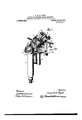
- Figure 1 is a perspective view of my machine, showing the same however as detached from its support or column;
- Fig. 2 is a side elevation, parts being broken away to better show some of the interior mechanism;
- Fig. 3 is a transverse section on the line .r-r of Fig 4;;
- Fig. 3' is a detail view of the cam plate;
- Fig. at is a top plan view, )arts being shown in section:
- Fig. 5 is a retail perspective view of the stationary crease gage for holdin" the work between the same and the tablea l igs. 1;
- T and S are respectively a side elevation, an edge view. and a bottom view of the finishing burnishing and feeding tool;
- Fig. 9 is an elevation of a series of different iuterehaugeable tables;
- Fig. 10 is :1 diagram illustrative of the various movements of the tool 'in a cycle of its operation.
- A designates a base plate or frame upon which the moving parts of the mechamsm are mounted. said plate bein angular as shown to provide a downwar v extending flange a at one end thereof for supportin a tubular guide or casing C for the adjusta le shank D of a work table E.
- the bottom of this casing is open for the passage of an adjusting screw 0 for regulating the tension of its usual outwardly-thrustin spring J, a cable or link being connect to said shank and running to any convenient operating device such as a treadle (not shown), and a bolt F loosely engaging an ear on the shank of the table and threaded into the base plate A affording a means for limiting the outward movement thereof under the pressure of its spring.
- the work table just referred to is of the radially tapering or beveled disk type.
- the special manner of removably supporting the table upon its shank or support enables the provision of a series of interchangeable tables such as illustrated in Fig. 9, all of the tables a like portion formed complementary to and adapted to rotatably interfit with the support or shank.
- Rigidly mounted upon the base A is an angle bracket G having a vertical portion 9 and a right angle portion 9 arranged in substantially a horizontal lane and offset at its end to project forw y, said forwardly projecting pert-ion being bifurcated to form separated fingers g overhanging the work table to constitute a crease gage between which and the table the work is frictionally held owing to the upward pressure of the table under the influence of its spring.
- the tool holder I is so mounted and operatively associated with the other parts of the working mechanism that the same may be given its desired vertical, lateral and reeiprccatory movements to accomplish the effect desired on the sole, as will presently appear.
- the rotation of the shaft carries the raised portion of the cam just referred to away from the roller M of the tool holder and permits the holder and tool carried thereby to drop under the influence of a spring N arranged between the bottom face of the base A and an adjustable nut n on the lower end of a rod 1 passing loosely through an aperture in said base and connected at its upper end to the tool holder I, it being understood that the tool holder is pivoted at its rear end, as at o to the upper end of a pivoted bell crank lever 0 mounted on the base.
- V is an adjustable stop having a threaded sleeve W engaging the arm r for regulating the tension of the laterally shifting spring R.
- Xuts Y, Z threaded on the rod R are arranged to abut the end of the sleeve W to limit the lateral movement of the holder and tool under the influence of the spring R.
- a rigidly mounted burnishing tool formed to engage stitch printedons on the edges of shoe soles. and means for rapidly reciproeating the same while in uninterrupted surface contact with the same impressions.
- a rigidly mounted burnishing tool formed to engage stitch imprexions on the edges of shoe soles, and means whereby the same may be rapidly reciprocated in a direction substantially in line with an im rcmicn and without withdrawing the tool engagement with such im ression.
- a bnrnishing tool having but a single burnishing edge formed to engage stitch impressions on the edges of shoe soles, and means for rapidly reciprocating the same while in engagement with an impression whereby each impression may be burnished independently of the others.
- A. bnrnishing tool having but a single bnrnisbing edge, said edge be formed to engage stitch impressions on t e edges of shoe soles, and means for rapidly recipro- --ca the same in a direction substantially in i ith said 6.
- a tool comprising a pivotally mounted reciprocal arm having a burnishmg edge formed integral therewith and shaped to engage stitch impressions on the edges of shoe soles. and means for impart-- mg a rapid reciprocating polishing move mentto said tool substantially in line with said impressions.
- a burnishing tool formed to engage stitch impressions on the edges of shoe soles, means for clamping the work, means for initially operating the tool to cause the same to can gage an impression, and means for subsequently imparting a rapid reciprocating movementto said tool while in engagement with said impression.
- a burnishing tool formed to engage stitch impressions on the edges of shoe soles, means for clamping the work, means for initially operating the tool to cause the same to engage an impression and to release the work from the clamping action means for shifting the tool to feed the work, and means for imparting a rapid reciprocating move ment to said tool while in engagementwith said impression to burnish the same.
- a burnishing tool formed to engage stitch impressions on the edfi of shoe soles, means for clamping the work, and instrumentalities for operating the tool to shift the work and to impart rapid reciprocating movements thereto while in engagement with an impression to burnish the same.
- a burnishing tool formed to engage stitch markedons on the edges of shoe soles, means for clamping the work, and instrumentalities for actuating the same whereby 105 during a cycle of operations the tool will engage an elevationon and laterally to feed the work. and also reciprocate rapidly while in engagement with the printedon to finish and burnish the same.
- a burnishing tool formed to engage stitch laminateons on the edges of shoe soles, means for clamping the work, means for causing the tool to engage an imtpresslon under maximum pressure to release e work a from the clamp, means for shifting the tool laterally to feed the work, means for relieving the maximum prasnre between the tool and the work to permit the clamp to engage 120 the work. and means for imparting a rapid reciprocating movement to said tool while in engagement with said trophyon.
- 11 ol formed to engage 125 stitch impressions on the edges of shoe soles, means for causing the tool to engage an impression under maximum pressure to feed the work, means for the tool laterally to cause it to feed the work, means ior 13 relieving the maximum pressure between the tool and the work, and means for imparting a rapid reciprocating movement to said tool while in engagement with said impression.
- a burnishing tool formed to engage stitch impressions on the edges of shoe soles.
- a burnishing tool formed to engage stitch impressions on the edges of shoe soles, a supportfor the work, means for causing the tool to engage an impression and for shifting the same laterally to feed the work, means for imparting a rapid reciprocating movement to said tool while in engagement with said impression, and means for return ing the tool to its starting position.
- a burnishing tool formed to engage stitch impressions on the edges of shoe soles, a holder for the work, means for causing the tool to engage an im ression and for shifting the same to f the work, means for imparting rapid polishing movements to said tool while in engagement with said impression, and means for returning the tool to its st ition.
- a burnishing tool formed to engage stitch printedons on the edges of shoe soles, a holder for the work, means for causing the tool to engage an impression and for the same to feed the work, means for imparting a rapid reciprocating move ment to said tool substantially in line with said impression to polish the latter, and means for returning the tool to its starting position.
- a tool havingla burnishing edge formed to engage stit with said tool.
- a tool in a machine of the character described, a tool, a support for the work, means for initially operating the tool to indent the work, means for imparting rapid reciprocating movements to the tool while in engagementwith the indentation to burnish the same, and means for actuating the tool whereby it will feed the work.
- a burnishing tool formed to engage indentations, a support for the work, means for imparting rapid reciprocating move ments to said tool while in engagement with an indentation, and means for actuating the tool to feed the work.
- an ornamenting tool constructed to hold said tool and having a vertical, reciprocating motion, a lateral feed motion, and a back and forth polishing motion, and means for operating said tool holder.
- an ornamenting tool having an inclined working edge, an oscillating tool holder constructed to hold the said ornamenting tool and to impart to it an up and down motion, a lateral feed motion and to admit the lower or working end of the said tool to glide over and polish the ornament made by the previous action of the said tool, and means for operating the said tool holder.
- an ornamenting tool having an inclined workin edge and means for giving it an up and down motion. a lateral feed movement, and a gliding polishing movement.
- an ornamenting tool mounted to have a lateral feed motion and a back and forth polishing motion, and instrumentalities for imparting the back and forth polishing motion to the tool while in engagement with the work.
- an ornamenting tool mounted to be raised and lowered and to have a back and forth polishing movement while the tool is in continuous engagement with the work, and means acting automatically to eliect all of said movements of the tool.
- an ornamenting tool In a. machine of the character described, an ornamenting tool, a work support, means for clamping the work to said support, and instrumentalitis for imparting a feed motion to the tool, and a back and 18.
- an ornamenting tool, a work supedges of shoe'soles, and means for imparting 3 port means for clamping the work to said rapid polishing movements to said tool 1 work support, and inst-rumentalities for im- 55 while in engagement with an impression, in i parting a. feed motion to the tool, and a back 130 g'agementwith the work and forth polishing inotion thereto while in engagement with the work, said instrumentalities including means acting automatically to raise and lower the tool.
- an ornamenting tool mounted to hate :1 feed motion and repeated polishing motions, and means for effecting the re peated polishing motions of the tool while in engagement with the work.
- an ornamenting' tool mounted to have a feed motion and repeated polishing motions, and instrumentalitis for efi'ectin the feed motion of the tool, and the repeated polishing motions thereof while in engage ment with the work, said instrumentalitles includedin means acting automatically to raise and lower the tool.
- a stitchdmpresion machine com prising co'ii ting work-supporting memhers engagmg the upper and lower surfaces of the work and operating to restrict the vertical movements therepf, a tool, and toolactuating means operating to vibrate the tool into and out of agement with the surface of the work to cm stitch impressions and longitudinally with respect to the impressions when in contact therewith to banish the estimatedons'.
- an impression tool, and tool actuating means operated by the machine to move the tool into and out of engagement with the work and to rapidly reciprocate the tool substantially in line with the impression when in engagement with the work.
- an impression tool, and tool actuating means operating to advance the tool toward the work to indent the work, then relier'e the pressure of the tool slightly and then rapidly reciprocate the tool lengthwise theimpression while its pressure is relieved.
- a burnishing tool formed to engage stitch markedons on the edges of shoe soles, automatic means for initially operating the tool to cause it to engage an impression, and means for subsequently imparting a rapid reciprocating movement to said tool while in engagement with said impression.
- a machine of the character described having in combination, a work support, an impression tool for engaging a stitch impreszion, a cam for redprocating the tool engthwise the imprmsion to burnish it, and a second cam to more the tool toward and from the work into and out of engagement with the imprssion before and after the burnishing movement.
Landscapes
- Finish Polishing, Edge Sharpening, And Grinding By Specific Grinding Devices (AREA)
Description
L. W. G. PLYNT.
HAUHIKE FOR BUB-FISHING STITCH IMPBESSIONS.
nruonml rlLzn JULY 31, 1905. xnnwnn low. 9, 1911.
Patented July 29, 1913.
4 SHEETS-SHEET 1.
Iauis H4 6. 71 m:
L. W. G. PLYNT.
I CHINE FOB BUBRISHHIG STITCH IMPRESSIONS.
4121.101110] nun 1113131, 1905. xnnnn 10?. n. 1911.
1,069,090, Patented m 29, 1913.
M: E Jazz is "f 6'. 7272111,
L. w. G. FLYNT.
momma roa BUBNISHING s'mcn mrnnssmns.
PPLIGLTIOI FILED JULY 31, 1905. EEIEWED IOY. 9 1911. 1,069,090.
Patented July 29, 1913.
& suns-sum a.
, L. W. G. PLYNT.
HACHINE POE BUBNISHIHG STITCH IMPRESSIONS.
nummmx nun 1111-131. 1905. xmmwzn 10v. 9. 1911.
1,069,090. Patented July 29, 1913.
4 SHEETS-BEBE! 4.
2 m Jonas ma. m
UNITED STA'lllilS OFFICE.
LOUIS W. G. I'LYNT, OF BOCHBTEB, NEW YORK, ASSIGNOB, BY HESNE ASSIGNMENTS,
TO UNITED SHOE HAOHH'EBY COMPANY, OF PATEBSON, NEW JERSEY, A CORPO- RATION OF NEW JERSEY.
Specification of Letters Patent.
Patented J 1113- 29, 1913.
Application filed July 31, 1905, Serial Ho. 272,061. Renewed November 9, 1911. Serial No. 659,444..
T 0 all whom it may concern:
This invention relates to machines fori operating upon the projecting edges of the j soles of boots and shoes and is herein shown 5 embodied in a machine which is intended to burnish the stitch impressions that are commonly formed upon said edges. It will be understood however that certain features of the invention are not limited for use with a machine for burnishing stitch impresions but may be employed with advantage in machines for forming stitch impressions upon the edges of shoe soles or in machines which initially form the impressions and thereafter burnish the impressions so formed.
The primary object of .the present invention is to provide a machine of the above type which is adapted to produce work of a superior quality and which may be operated with a minimum amount of etfort on the part of the operator.
Another object of the invention is to improve generally the construction of machines of the above type. 'ith these objects in view a feature of the present invention consists in the provision in a machine for operating upon the edges of shoe soles of a non-rotatable tool havingan acting edge formed com lementary to the impresions to beform imparting an tool while its the work.
The present invention also contemplates the provision in a machine of this character of means for creating a holding pressure between the tool and the work and means for shifting said tool laterally to feed the work. Preferably there is provided means for relieving the holding pressure prior to the operating movement of the tooL a comgtrttively slight pressure being reserved eentheactmgedgeofthet and the or burnished and means for :perating movement to the ge 1s m engagement with 1 surface of the work during the finishing or Be it known that I. LOUIS G. Fnrx'r, i a subject of Great Britain, residing at Rochester. in the county of Monroe and i my present invention. State of Xew York. have invented certain new and useful Improvements in Machines 5 for Burnishing Stitch Impressions, of which the following is a specification, reference; being had therein to the accompanying 10 drawing.
polishing movement of the former.
The oregoing characteristic features of as also other novel features in -the construction and arrangement of l (parts of a practical machine made in acco ance with the invention, will be more fully understood from the detailed description hereinafter contained when read g in connection with the accompanying drawings forming part hereof and wherein a convenient embodiment of said invention is illustrated.
As will be duly appreciated the embodiment of the invention above noted which I have selected as a fitting disclosure of the invention, embraces a tool which notonly performs its desired function of finishing and burnishing the imitation stitch impressions but acts also to feed the work to carry the last burnished impresion away from operative relation with the tool. and to pre sent the next adjoining nnburnished impression mto position to be enga bv said tool, the movement of the too in this instance being first to descend under relatively heavy or maximum pressure into engagement with the unburm'shed impresion, thence laterally to feed the work a distance ual to the width of space intermediate a joining impresions. thence vertically to a comparatively slight extent to relieve the presure between the e im ression and the edge of the tool while at t same time maintaining surface en gement therebetween under relatively 'ght presnre, thence back and forth in a horizontal direction whereby to reciprocate in a line lengthwise of the impression.--and incidentally lengthwise of the edge of the tool.to polish of any rough of the impression or indentation as initially formed and to straighten and hnrnish the some, thence still farther vertically away from engagement with the work, and finally back in a reverse lateral direction to the starting point of its operation, that is. in a position to again descend into engagement with the next adommg impression.
In the drawings, Figure 1 is a perspective view of my machine, showing the same however as detached from its support or column; Fig. 2 is a side elevation, parts being broken away to better show some of the interior mechanism; Fig. 3 is a transverse section on the line .r-r of Fig 4;; Fig. 3' is a detail view of the cam plate; Fig. at is a top plan view, )arts being shown in section: Fig. 5 is a retail perspective view of the stationary crease gage for holdin" the work between the same and the tablea l igs. 1;. T and S are respectively a side elevation, an edge view. and a bottom view of the finishing burnishing and feeding tool; Fig. 9 is an elevation of a series of different iuterehaugeable tables; and Fig. 10 is :1 diagram illustrative of the various movements of the tool 'in a cycle of its operation.
Referring more specifically to the drawings. wherein like reference characters refer to tan-responding parts in the several news, A designates a base plate or frame upon which the moving parts of the mechamsm are mounted. said plate bein angular as shown to provide a downwar v extending flange a at one end thereof for supportin a tubular guide or casing C for the adjusta le shank D of a work table E. The bottom of this casing is open for the passage of an adjusting screw 0 for regulating the tension of its usual outwardly-thrustin spring J, a cable or link being connect to said shank and running to any convenient operating device such as a treadle (not shown), and a bolt F loosely engaging an ear on the shank of the table and threaded into the base plate A affording a means for limiting the outward movement thereof under the pressure of its spring. The work table just referred to is of the radially tapering or beveled disk type. but in the present instance contains additional merit in that the same has a rec& c in its lower surface adapted to removably receive a stub pintle e on the head of the shank D, the upper surface of said head being arranged at an incline so that the tapering surface of the table when in operating position thereon is approximately parallel with the lane of reciprocation of the tool H to be ereinafter further defined. The peripheral portion of the table at the point of greatest strain thereon, that is directly beneath the tool, is supported upon a large anti-friction roller d di at a right angle to the under surface of the table and in peripheral engagement therewith. The special manner of removably supporting the table upon its shank or support enables the provision of a series of interchangeable tables such as illustrated in Fig. 9, all of the tables a like portion formed complementary to and adapted to rotatably interfit with the support or shank. Rigidly mounted upon the base A is an angle bracket G having a vertical portion 9 and a right angle portion 9 arranged in substantially a horizontal lane and offset at its end to project forw y, said forwardly projecting pert-ion being bifurcated to form separated fingers g overhanging the work table to constitute a crease gage between which and the table the work is frictionally held owing to the upward pressure of the table under the influence of its spring.
,Arranged to work in the s ace intermediate the fingers g" is the finis ing and burnishing implement H, the same comprising a flat non r'otatable shank fixedly secured in a vieldable arm a of a holder I, and a single substantially horizontally disposed finishing and burnishing edge h of a shape complementary to the shape of the indentations to be treated. the only difl'erence between the shape of said indentations and said burnishing edge residing in the fact that the walls of the latter are disposed at a somewhat greater angle with respect to each other than the correspondin relation of the side walls or surfaces of the former, the purpose of this being to insure a suflicient surface contact between the burnishing edge of the tool and the side surfaces of the indentations while preventing any perceptible engagement of said edge with the base of the in dentations which would tend to deepen the indentations as initially formed, and which in many instances is not desirable.
The tool holder I is so mounted and operatively associated with the other parts of the working mechanism that the same may be given its desired vertical, lateral and reeiprccatory movements to accomplish the effect desired on the sole, as will presently appear.
J is an operating shaft mounted to rotate in suitable bearings formed in uprights J at opposite sides of the frame A, said shaft being adapted to be rotated through the medium of any convenient driving mechanism, that shown including a grooved wheel or pulley K for engagement by a belt in communication with any suitable source of war. to the shaft J is a cam plate havin a raised portion 1 on its riphery arrang to enga e a roller M carried by the tool holder I at the top thereof whereby the tool is in its initial or starting position ele vated to its highest position, or that indi cated as Starting position Fig. 10. The rotation of the shaft carries the raised portion of the cam just referred to away from the roller M of the tool holder and permits the holder and tool carried thereby to drop under the influence of a spring N arranged between the bottom face of the base A and an adjustable nut n on the lower end of a rod 1 passing loosely through an aperture in said base and connected at its upper end to the tool holder I, it being understood that the tool holder is pivoted at its rear end, as at o to the upper end of a pivoted bell crank lever 0 mounted on the base. the function of which latter will be soon pointed out, it be ing sufiic-ient to note at this oint that the second peripherally raised portion t on the opposite end of the bell crank ever carries a rod 0 under tension of another adjustable spring 0" similar to the one previously defined In connection with the holder. The up and down or vertical movement of the tool I 5 E t holder does not aifect the bell crank lever and its spring the latter during such move- 5 ment serving as a pivot only for the tool holder.
between the work table and the crease gage 1 and clamped therebetween prior to the dopressing of the implement as lastabove decam plate L engaging the overhanging or uppermost roller M on the tool hdlder to somewhat relieve the pressure of the tool on the surface of the indentation, it being noted that as soon as the cam t engages the holder, its spring X can no longer pull said holder and tool In a downward direction as before. This relieving of the ressure on the tool of course permits the tab e and work Of course the indented sole is interposed scribed, and when this is remembered it will be apparent that as the impression tool de- SCElll'lS it forcibly engages one of the indentattons of the sole, and owing to the comparatively greater strength of the spring X 5 the sole and work table are also depressed against the spring of the work table ta: free the work from engagement with the crease gage preparatory to the second movement of the tool which is to feed the work and which may now be followed. The rotation of the shaft continuing in the same direction as before carries the raised or thicker pon'ion of a side cam ring Q on the plate L away from a second roller P mounted upon a horizontal bracket on the tool holder,- which engagement as up to this stage of the operation held the tool and its holder from lateral movement,whereupon a horizontally disposed outwardly s rmg pressed rod R connected to the too holder and mounted to loosel play within an arm a on the nearest upri t J of the frame A will shift the tool holder and tool carried thereby laterally to the position marked "Third position (Fig. 10) which is for a distance equal to the desired length between adjoiningimpressions, and inasmuch as the tool remains in engagement with the impression enga ed by it in the first instance, the work is fed step by step with this lateral shifting of the tool to successively present the unburnished indentations in position to be burnished.
As soon as the implement reaches its third or burnishing position a peripherally corrugated portion S of the cam plate L comes into engagement with a third roller T near the pivotal point of the tool holder with the bell crank lever O and rapidly reciprocates the tool and holder in line with the burnishing edge of the tool, as also in line with the indentation being treated, to finish and burnish said indentation, the bell crank lever rocking on its pivot in short forward and reverse directions, alternately, and in rapid succession under the force of the corrugations just referred to and the spring 0". Previous to this burni a movement. however, the tool holder, an incidentally the tool; is elevated through the medium of a.
to raise sufiiciently to be again clamped between the table and crease gage.
F or the better class of work it 1s necessary to have a relatively slight degree of ressure between the burnishm edge an theis pivoted as at u to the rear portion of the main body of the holder I and arches over the 0 rating shaft, whence it extends forwar y to a pointnear the crease ga Said main body portion of the holder has a laterally extending lug or flange 11 through which loosely passes a screw U. the latter engaging at its inner end with the forward portion of the arm 1 and atits outer end carrying an adjustable nut u" interposed between which and the bottom of the lug is a relatively light sprin coiled upon the screw. Thus the arm I is constantly yieldably premed downwardly.
When the indentation is properly finished and burnished the raised portion I of the cam engages the roller 11 to elevate the tool holder and tool. and the cam ring Q again engages the roller Q to shift them laterally in a reverse direction back to the starting point, thereby completing a cycle of operation.
V is an adjustable stop having a threaded sleeve W engaging the arm r for regulating the tension of the laterally shifting spring R. Xuts Y, Z threaded on the rod R are arranged to abut the end of the sleeve W to limit the lateral movement of the holder and tool under the influence of the spring R.
'hen the work table E and work thereon is depressed away from the fingers g!" of the crease gage to permit the feeding movement of the work. it will be apparent that the relatively heavy spring X pulls the lever I bodily downward on its pivot 0. and the working edge of the burnishing tool H carried by the aun'liary lever i pivoted at it being resisted by the work with which said edge engages, the tendency of the downward movement of the lever I is to compress the light spring upon the rod U so that the spring X not only acts to draw downwardly the main lever I but also therewith the auxiliary lever which enablesi the depres ion of the work table and work against the action of the table supporting spring at as herein previously set forth.
It is to be understood that many changes and alterations may he made in the struc ture herein disclosed without departing from the spirit of the invention, and also that the invention is susceptible of other embodiments than that described.
The burnishing machine herein disclosed so far as the broader aspect of the invention is concerned. is covered by claims in my Patent No. 845.939. granted March 5, 1907. on a copending application. Serial No. 231.133. filed November 2. 190;. Therefore such claims are not included herein.
In some of the claims herein, I will dc fine the bnrnishing tool as being rigidly mounted. meaning thereby that the tool is held relative to its support or carrier against rotation in a lateral direction in contradistinction to the rotatable tool shown in my above stated application.
What I claim as my invention and des re to secure by Letters Patent is 1. In a machine of the character described. a rigidly mounted burnishing tool formed to engage stitch impressions on the edges of shoe soles, and means for rapidly reciproeating the same substantially in line with said impresions.
2. In a machine of the character described. a rigidly mounted burnishing tool formed to engage stitch impresions on the edges of shoe soles. and means for rapidly reciproeating the same while in uninterrupted surface contact with the same impressions.
3- In a machine of the character described. a rigidly mounted burnishing tool formed to engage stitch imprexions on the edges of shoe soles, and means whereby the same may be rapidly reciprocated in a direction substantially in line with an im rcmicn and without withdrawing the tool engagement with such im ression.
4. In a machine the character described, a bnrnishing tool having but a single burnishing edge formed to engage stitch impressions on the edges of shoe soles, and means for rapidly reciprocating the same while in engagement with an impression whereby each impression may be burnished independently of the others.
5. A. bnrnishing tool having but a single bnrnisbing edge, said edge be formed to engage stitch impressions on t e edges of shoe soles, and means for rapidly recipro- --ca the same in a direction substantially in i ith said 6. In a machine o the character described,
as a tool comprising a pivotally mounted reciprocal arm having a burnishmg edge formed integral therewith and shaped to engage stitch impressions on the edges of shoe soles. and means for impart-- mg a rapid reciprocating polishing move mentto said tool substantially in line with said impressions.
T. In a machine of the character described, a burnishing tool formed to engage stitch impressions on the edges of shoe soles, means for clamping the work, means for initially operating the tool to cause the same to can gage an impression, and means for subsequently imparting a rapid reciprocating movementto said tool while in engagement with said impression.
8. In a machine of the character described, a burnishing tool formed to engage stitch impressions on the edges of shoe soles, means for clamping the work, means for initially operating the tool to cause the same to engage an impression and to release the work from the clamping action means for shifting the tool to feed the work, and means for imparting a rapid reciprocating move ment to said tool while in engagementwith said impression to burnish the same.
9. In a machine of the character described, a burnishing tool formed to engage stitch impressions on the edfi of shoe soles, means for clamping the work, and instrumentalities for operating the tool to shift the work and to impart rapid reciprocating movements thereto while in engagement with an impression to burnish the same.
10. In a machine of the character described, a burnishing tool formed to engage stitch impresions on the edges of shoe soles, means for clamping the work, and instrumentalities for actuating the same whereby 105 during a cycle of operations the tool will engage an impresion and laterally to feed the work. and also reciprocate rapidly while in engagement with the impresion to finish and burnish the same.
11. In a machine of the character de- 119 scribed, a burnishing tool formed to engage stitch impresions on the edges of shoe soles, means for clamping the work, means for causing the tool to engage an imtpresslon under maximum pressure to release e work a from the clamp, means for shifting the tool laterally to feed the work, means for relieving the maximum prasnre between the tool and the work to permit the clamp to engage 120 the work. and means for imparting a rapid reciprocating movement to said tool while in engagement with said impresion.
In a machine of the character described, 11 ol formed to engage 125 stitch impressions on the edges of shoe soles, means for causing the tool to engage an impression under maximum pressure to feed the work, means for the tool laterally to cause it to feed the work, means ior 13 relieving the maximum pressure between the tool and the work, and means for imparting a rapid reciprocating movement to said tool while in engagement with said impression.
13. In a machine of the character described. a burnishing tool formed to engage stitch impressions on the edges of shoe soles. means for causing the tool to engage an impression under maximum pressure, means for subsequently shifting the tool laterally to cause it to feed the work, means for relieving the maximum presure between the tool and the work, and means for imparting a rapid reciprocating movement to said tool while in engagement with said impression, in combination with auxiliary means for maintaining a relatively light pressure between the tool and the work during the reciprccating movement of the former.
H. In a machine of the character de scribed, a burnishing tool formed to engage stitch impressions on the edges of shoe soles, a supportfor the work, means for causing the tool to engage an impression and for shifting the same laterally to feed the work, means for imparting a rapid reciprocating movement to said tool while in engagement with said impression, and means for return ing the tool to its starting position.
15. In a machine of the character described, a burnishing tool formed to engage stitch impressions on the edges of shoe soles, a holder for the work, means for causing the tool to engage an im ression and for shifting the same to f the work, means for imparting rapid polishing movements to said tool while in engagement with said impression, and means for returning the tool to its st ition.
16. ln a hia t iliine of the character described, a burnishing tool formed to engage stitch impresions on the edges of shoe soles, a holder for the work, means for causing the tool to engage an impression and for the same to feed the work, means for imparting a rapid reciprocating move ment to said tool substantially in line with said impression to polish the latter, and means for returning the tool to its starting position.
17. In a machine of the character de scribed, a tool havingla burnishing edge formed to engage stit with said tool.
impressions on the edges of shoe soles, and means for rapidly reciprocat' the same substantially in line e, in combination with means for clamping the work independently of the forth polishing motion thereto while in encombinat-ion with means for clamping the work independently of the tool.
19. In a machine of the character described, a tool, a support for the work, means for initially operating the tool to indent the work, means for imparting rapid reciprocating movements to the tool while in engagementwith the indentation to burnish the same, and means for actuating the tool whereby it will feed the work.
20. In a machine of the character described, a burnishing tool formed to engage indentations, a support for the work, means for imparting rapid reciprocating move ments to said tool while in engagement with an indentation, and means for actuating the tool to feed the work.
:21. In a machine of this class, an ornamenting tool, an oscillating tool-holder constructed to hold said tool and having a vertical, reciprocating motion, a lateral feed motion, and a back and forth polishing motion, and means for operating said tool holder.
22. In a machine of this class, an ornamenting tool having an inclined working edge, an oscillating tool holder constructed to hold the said ornamenting tool and to impart to it an up and down motion, a lateral feed motion and to admit the lower or working end of the said tool to glide over and polish the ornament made by the previous action of the said tool, and means for operating the said tool holder.
In a machine of this clam, an ornamenting tool having an inclined workin edge and means for giving it an up and down motion. a lateral feed movement, and a gliding polishing movement.
24. In a machine of the character described, an ornamenting tool mounted to have a lateral feed motion and a back and forth polishing motion, and instrumentalities for imparting the back and forth polishing motion to the tool while in engagement with the work.
25. In a machine of the character described, an ornamenting tool mounted to be raised and lowered and to have a back and forth polishing movement while the tool is in continuous engagement with the work, and means acting automatically to eliect all of said movements of the tool.
26. In a. machine of the character described, an ornamenting tool, a work support, means for clamping the work to said support, and instrumentalitis for imparting a feed motion to the tool, and a back and 18. In a machine of the character de- 125 scribed, a tool havingla burnishmg edge? 27. In a machine of the character deformed to engage stitc impresions on the scribed, an ornamenting tool, a work supedges of shoe'soles, and means for imparting 3 port, means for clamping the work to said rapid polishing movements to said tool 1 work support, and inst-rumentalities for im- 55 while in engagement with an impression, in i parting a. feed motion to the tool, and a back 130 g'agementwith the work and forth polishing inotion thereto while in engagement with the work, said instrumentalities including means acting automatically to raise and lower the tool.
28. In a machine of the character described, an ornamenting tool mounted to hate :1 feed motion and repeated polishing motions, and means for effecting the re peated polishing motions of the tool while in engagement with the work.
29. In a machine of the character described, an ornamenting' tool mounted to have a feed motion and repeated polishing motions, and instrumentalitis for efi'ectin the feed motion of the tool, and the repeated polishing motions thereof while in engage ment with the work, said instrumentalitles includin means acting automatically to raise and lower the tool.
30. A stitchdmpresion machine com prising co'ii ting work-supporting memhers engagmg the upper and lower surfaces of the work and operating to restrict the vertical movements therepf, a tool, and toolactuating means operating to vibrate the tool into and out of agement with the surface of the work to cm stitch impressions and longitudinally with respect to the impressions when in contact therewith to banish the impresions'.
31. In a machine of the character described, an impression tool, and tool actuating means operated by the machine to move the tool into and out of engagement with the work and to rapidly reciprocate the tool substantially in line with the impression when in engagement with the work.
32. In a machine of the character described, an impression tool, and tool actuating means operating to advance the tool toward the work to indent the work, then relier'e the pressure of the tool slightly and then rapidly reciprocate the tool lengthwise theimpression while its pressure is relieved.
33. In a machine for burnishing stitch impi'essions, a burnishing tool formed to engage stitch impresions on the edges of shoe soles, automatic means for initially operating the tool to cause it to engage an impression, and means for subsequently imparting a rapid reciprocating movement to said tool while in engagement with said impression.
3%. A machine of the character described having in combination, a work support, an impression tool for engaging a stitch impreszion, a cam for redprocating the tool engthwise the imprmsion to burnish it, and a second cam to more the tool toward and from the work into and out of engagement with the imprssion before and after the burnishing movement.
In testimony whereof I afiix my signature in presence of two witueses.
LOUIS W. G. FLYKT.
Qcxamw. Boom.
mott'hispa'ieni'naiie mama m I" cents each, ti was; we Colilmiisiofia! Patents. wmnc:
Publications (1)
| Publication Number | Publication Date |
|---|---|
| US1069090A true US1069090A (en) | 1913-07-29 |
Family
ID=3137328
Family Applications (1)
| Application Number | Title | Priority Date | Filing Date |
|---|---|---|---|
| US1069090D Expired - Lifetime US1069090A (en) | A corpo |
Country Status (1)
| Country | Link |
|---|---|
| US (1) | US1069090A (en) |
-
0
- US US1069090D patent/US1069090A/en not_active Expired - Lifetime
Similar Documents
| Publication | Publication Date | Title |
|---|---|---|
| US1144340A (en) | Embossing-machine. | |
| US1595674A (en) | Heel-blank-sawing machine | |
| US3000024A (en) | Shoe machine | |
| US1197439A (en) | Upper-forming machine. | |
| US860377A (en) | Stitch-impression finishing-machine. | |
| US1932818A (en) | Heel shaping machine | |
| US1645515A (en) | Innersole-forming machine | |
| US1011737A (en) | Seam-rubbing machine. | |
| US845939A (en) | Burnishing-machine for imitation-stitch impressions or indentations. | |
| US855401A (en) | Impression-stitch machine. | |
| US1195965A (en) | Machine for molding toe portions oe shoe-uppers | |
| US1098266A (en) | Ironing-machine. | |
| US939105A (en) | Machine for pressing and shaping the backs of shoes. | |
| US874504A (en) | Automatic boot and shoe leveling machine. | |
| US872578A (en) | Machine for producing sewing-ribs on the soles of boots and shoes. | |
| US958026A (en) | Shoe-sole-edge setter. | |
| US1161058A (en) | Machine for operating on heels. | |
| US2377377A (en) | Indenting machine | |
| US225228A (en) | Burnishing-machine for boot and shoe soles | |
| US1001078A (en) | Machine for operating on shoes. | |
| US1462457A (en) | Metal-basket-corrugating machine | |
| US2198456A (en) | Machine for turning and binding the edges of leather | |
| US2358787A (en) | Indenting machine | |
| US662416A (en) | Stitch-separator. | |
| US1034851A (en) | Edge-setting machine. |