US10690905B2 - Imaging module, endoscope, and method of manufacturing imaging module - Google Patents
Imaging module, endoscope, and method of manufacturing imaging module Download PDFInfo
- Publication number
- US10690905B2 US10690905B2 US15/434,302 US201715434302A US10690905B2 US 10690905 B2 US10690905 B2 US 10690905B2 US 201715434302 A US201715434302 A US 201715434302A US 10690905 B2 US10690905 B2 US 10690905B2
- Authority
- US
- United States
- Prior art keywords
- image
- sensing device
- lens
- positioning hole
- optical axis
- Prior art date
- Legal status (The legal status is an assumption and is not a legal conclusion. Google has not performed a legal analysis and makes no representation as to the accuracy of the status listed.)
- Expired - Fee Related, expires
Links
- 238000003384 imaging method Methods 0.000 title claims abstract description 92
- 238000004519 manufacturing process Methods 0.000 title claims description 21
- 238000003780 insertion Methods 0.000 claims abstract description 65
- 230000037431 insertion Effects 0.000 claims abstract description 65
- 230000003287 optical effect Effects 0.000 claims abstract description 45
- 238000013459 approach Methods 0.000 claims abstract description 6
- 239000000758 substrate Substances 0.000 claims description 19
- 229910052751 metal Inorganic materials 0.000 claims description 4
- 239000002184 metal Substances 0.000 claims description 4
- 239000000853 adhesive Substances 0.000 description 16
- 230000001070 adhesive effect Effects 0.000 description 16
- 230000007613 environmental effect Effects 0.000 description 4
- 230000015556 catabolic process Effects 0.000 description 3
- 239000004020 conductor Substances 0.000 description 3
- 238000006731 degradation reaction Methods 0.000 description 3
- 238000013461 design Methods 0.000 description 3
- 230000006866 deterioration Effects 0.000 description 3
- 238000006073 displacement reaction Methods 0.000 description 3
- 230000002411 adverse Effects 0.000 description 2
- 230000002093 peripheral effect Effects 0.000 description 2
- 229910000679 solder Inorganic materials 0.000 description 2
- 229910000838 Al alloy Inorganic materials 0.000 description 1
- 238000007792 addition Methods 0.000 description 1
- 230000000295 complement effect Effects 0.000 description 1
- 230000007423 decrease Effects 0.000 description 1
- 230000007547 defect Effects 0.000 description 1
- 230000000694 effects Effects 0.000 description 1
- 238000010292 electrical insulation Methods 0.000 description 1
- 238000003754 machining Methods 0.000 description 1
- 239000000463 material Substances 0.000 description 1
- 229910044991 metal oxide Inorganic materials 0.000 description 1
- 150000004706 metal oxides Chemical class 0.000 description 1
- 238000000034 method Methods 0.000 description 1
- 238000012986 modification Methods 0.000 description 1
- 230000004048 modification Effects 0.000 description 1
- 229920005989 resin Polymers 0.000 description 1
- 239000011347 resin Substances 0.000 description 1
- 239000004065 semiconductor Substances 0.000 description 1
- 229920002050 silicone resin Polymers 0.000 description 1
- 238000004088 simulation Methods 0.000 description 1
- 239000010935 stainless steel Substances 0.000 description 1
- 229910001220 stainless steel Inorganic materials 0.000 description 1
- 238000006467 substitution reaction Methods 0.000 description 1
Images


Classifications
-
- G—PHYSICS
- G02—OPTICS
- G02B—OPTICAL ELEMENTS, SYSTEMS OR APPARATUS
- G02B23/00—Telescopes, e.g. binoculars; Periscopes; Instruments for viewing the inside of hollow bodies; Viewfinders; Optical aiming or sighting devices
- G02B23/24—Instruments or systems for viewing the inside of hollow bodies, e.g. fibrescopes
- G02B23/2476—Non-optical details, e.g. housings, mountings, supports
- G02B23/2484—Arrangements in relation to a camera or imaging device
-
- A—HUMAN NECESSITIES
- A61—MEDICAL OR VETERINARY SCIENCE; HYGIENE
- A61B—DIAGNOSIS; SURGERY; IDENTIFICATION
- A61B1/00—Instruments for performing medical examinations of the interior of cavities or tubes of the body by visual or photographical inspection, e.g. endoscopes; Illuminating arrangements therefor
- A61B1/04—Instruments for performing medical examinations of the interior of cavities or tubes of the body by visual or photographical inspection, e.g. endoscopes; Illuminating arrangements therefor combined with photographic or television appliances
- A61B1/05—Instruments for performing medical examinations of the interior of cavities or tubes of the body by visual or photographical inspection, e.g. endoscopes; Illuminating arrangements therefor combined with photographic or television appliances characterised by the image sensor, e.g. camera, being in the distal end portion
- A61B1/051—Details of CCD assembly
-
- H—ELECTRICITY
- H04—ELECTRIC COMMUNICATION TECHNIQUE
- H04N—PICTORIAL COMMUNICATION, e.g. TELEVISION
- H04N23/00—Cameras or camera modules comprising electronic image sensors; Control thereof
- H04N23/50—Constructional details
- H04N23/55—Optical parts specially adapted for electronic image sensors; Mounting thereof
-
- H—ELECTRICITY
- H04—ELECTRIC COMMUNICATION TECHNIQUE
- H04N—PICTORIAL COMMUNICATION, e.g. TELEVISION
- H04N23/00—Cameras or camera modules comprising electronic image sensors; Control thereof
- H04N23/50—Constructional details
- H04N23/555—Constructional details for picking-up images in sites, inaccessible due to their dimensions or hazardous conditions, e.g. endoscopes or borescopes
-
- H04N5/2254—
-
- G—PHYSICS
- G02—OPTICS
- G02B—OPTICAL ELEMENTS, SYSTEMS OR APPARATUS
- G02B7/00—Mountings, adjusting means, or light-tight connections, for optical elements
- G02B7/02—Mountings, adjusting means, or light-tight connections, for optical elements for lenses
-
- H04N2005/2255—
Definitions
- the present invention relate to an imaging module, an endoscope, and a method of manufacturing an imaging module.
- An imaging module used in an endoscope or the like is provided with, for example, an image-sensing unit including an image-sensing device and a lens unit (lens) optically connected to the image-sensing device (for example, refer to Japanese Patent No. 5450704, and hereinbelow referred to as Patent Document 1).
- an image-sensing device (particularly, a cover that covers the surface of the image-sensing device) and a lens unit are fixed to each other via an adhesive.
- One aspect of the invention has an object thereof to provide an imaging module, an endoscope, and a method of manufacturing an imaging module, which can stably obtain excellent imaging performance.
- An imaging module includes: an image-sensing unit that includes an image-sensing device; a lens that has a front end and is optically connected to the image-sensing device; and a frame that is fixed in position with respect to the image-sensing device and includes a lens barrel having an insertion space, into which the front end is to be inserted in at least an optical axis direction.
- the insertion space is capable of receiving the lens in the direction such that the lens approaches the image-sensing device.
- the lens is fixed to the lens barrel at a position at which the lens is optically connected to the image-sensing device.
- the frame has: a first end at which an insertion opening is formed, the lens being to be inserted into the insertion opening; and a second end at which a positioning hole is formed, the positioning hole determining the position of the image-sensing device so that a light-receiving face is exposed to the insertion space.
- the positioning hole may be capable of limiting movement of the image-sensing device in a direction intersecting with the optical axis direction of the image-sensing device.
- the frame may include a movement limiter that limits the image-sensing device fixed in position by the positioning hole from moving into the insertion space.
- the lens barrel may have one or more slit-shaped cutouts formed in a direction from the first end to the second end.
- the frame may be made of a metal.
- An endoscope according to a second aspect of the invention includes the imaging module according to the aforementioned first aspect.
- a method of manufacturing an imaging module includes: preparing: an image-sensing unit comprising an image-sensing device; a lens having a front end; and a frame comprising a lens barrel having an insertion space into which the front end is to be inserted in at least an optical axis direction, the insertion space being capable of receiving the lens in a direction such that the lens approaches the image-sensing device in a state where movement of the lens in a direction intersecting with the optical axis direction is limited; positioning the image-sensing device of the image-sensing unit and the frame (first step); and inserting the lens into the insertion space and positioning the lens in the lens barrel at a position at which the lens is optically connected to the image-sensing device (second step).
- the imaging module since the imaging module includes the frame that can receive the lens in a state where movement of the lens in the direction intersecting with the optical axis is limited, it is possible to fix the position of the lens with a high level of accuracy at the position at which the lens is optically connected to the image-sensing device.
- FIG. 1A is a front view showing an imaging module according to the first embodiment.
- FIG. 1B is a cross-sectional side view showing the imaging module according to the first embodiment.
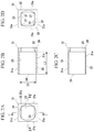
- FIG. 2A is a view showing a frame of the imaging module according to the first embodiment and is a front view showing a frame.
- FIG. 2B is a view showing the frame of the imaging module according to the first embodiment and is a cross-sectional view taken along the line I-I′ shown in FIG. 2A .
- FIG. 2C is a view showing the frame of the imaging module according to the first embodiment and is a cross-sectional view taken along the line II-II′ shown in FIG. 2A .
- FIG. 2D is a view showing the frame of the imaging module according to the first embodiment and is a rear view showing the frame.
- FIG. 3 is a cross-sectional view showing a front-end structure of an endoscope using the imaging module according to the first embodiment.
- FIG. 4A is an explanatory view showing a method of manufacturing the imaging module according to the first embodiment.
- FIG. 4B is an explanatory view showing the method of manufacturing the imaging module according to the first embodiment.
- FIG. 4C is an explanatory view showing the method of manufacturing the imaging module according to the first embodiment.
- FIG. 5A is an explanatory view showing the method of manufacturing the imaging module according to the first embodiment.
- FIG. 5B is an explanatory view showing the method of manufacturing the imaging module according to the first embodiment.
- FIG. 5C is an explanatory view showing the method of manufacturing the imaging module according to the first embodiment.
- FIG. 6A is an explanatory view showing the method of manufacturing the imaging module according to the first embodiment.
- FIG. 6B is an explanatory view showing the method of manufacturing the imaging module according to the first embodiment.
- FIG. 7A is a front view showing an imaging module according to a second embodiment and is a view showing a state where a lens unit is removed from the imaging module.
- FIG. 7B is a perspective view showing the imaging module according to the second embodiment and is a view showing a state where the lens unit is removed from the imaging module.
- FIG. 8 is a perspective view showing the imaging module according to the second embodiment and is a view showing a state where the lens unit is inserted into a frame.
- FIG. 9A is a view showing a modified example according to a frame and is a front view showing the frame.
- FIG. 9B is a view showing a modified example according to a frame and is a cross-sectional view III-III′ shown in FIG. 9A .
- FIG. 9C is a view showing a modified example according to a frame and is a cross-sectional view IV-IV′ shown in FIG. 9A .
- FIG. 9D is a view showing a modified example according to a frame and is a rear view showing the frame.
- FIG. 1A is a front view showing an imaging module 100 according to a first embodiment of the invention.
- FIG. 1B is a cross-sectional side view showing the imaging module 100 .
- the position at which an image-sensing device 4 is disposed on a flexible wiring substrate 10 is referred to as a front side
- the opposite side of the front side is referred to as a rear side.
- the XYZ orthogonal coordinate system may be adopted.
- the Z-direction is a front-back direction of the imaging module
- the X-direction is a direction orthogonal to the Z-direction and is perpendicular to a paperface in FIG. 1B .
- the Y-direction is a direction orthogonal to the X-direction and the Z-direction and is a vertical direction in FIG. 1B .
- the imaging module 100 includes an image-sensing unit 102 , a frame 31 , and a lens unit 20 (lens).
- the image-sensing unit 102 includes the flexible wiring substrate 10 (wiring part) and the image-sensing device 4 which is mounted on the flexible wiring substrate 10 .
- the flexible wiring substrate 10 includes: a device-mounted portion 11 ; and a pair of rear portions 12 and 13 (first rear portion 12 and second the rear portion 13 ) which are bent at both end portions of the device-mounted portion 11 , are directed in the thickness direction of the device-mounted portion, and extend toward the rear side.
- Wiring 14 is formed at least on an outer surface of the flexible wiring substrate 10 .
- the flexible wiring substrate 10 for example, a flexible wiring substrate having one surface on which wiring is formed can be used.
- the front surface (outer surface) of the device-mounted portion 11 is a mount surface 11 a on which the image-sensing device 4 is to be mounted.
- a conductor 2 is electrically connected via a conductive connector 15 made of solder or the like to the wiring 14 formed on the rear portion 13 of the flexible wiring substrate 10 .
- the conductor 2 is drawn from, for example, an electrical cable (not shown in the figure).
- the back (portion including the conductive connector 15 ) of the rear portions 12 and 13 of the flexible wiring substrate 10 is covered with an insulating tube 16 having, for example, electrical insulation.
- the insulating tube 16 is made of, for example, a resin material such as a silicone resin.
- the flexible wiring substrate 10 is an example of wiring part.
- CMOS complementary metal oxide semiconductor
- the image-sensing device 4 includes an image capturer 3 that is to be optically connected to the lens unit 20 .
- the image capturer 3 is provided on a front surface of the image-sensing device 4 .
- the shape of the image-sensing device 4 as seen in the front-back direction is, for example, a rectangular shape (for example, square).
- the image capturer 3 is electrically connected to the wiring 14 of the flexible wiring substrate 10 via an electrical circuit formed in the image-sensing device 4 .
- the direction of the optical axis A of the image capturer 3 coincides with, for example, the front-back direction.
- a light-receiving face 3 a of the image capturer 3 is the surface intersecting with the optical axis A 1 of the lens unit 20 .
- the light-receiving face 3 a of the image capturer 3 is the surface intersecting with the axis direction of the front end (forward end) of the conductor 2 .
- the light-receiving face 3 a is, for example, a surface along the XY plane.
- a bump 4 a that is electrically connected to an electrical circuit of the image-sensing device 4 is formed on the back surface of the image-sensing device 4 .
- the bump 4 a is, for example, a solder bump, a stud bump, a plated bump, or the like.
- the image-sensing device 4 is electrically connected to the mount surface 11 a of the device-mounted portion 11 of the flexible wiring substrate 10 via the bump 4 a by use of, for example, a flip-chip method.
- the lens unit 20 includes a cylindrical lens barrel 20 a ; and an object lens 23 that is incorporated into the inside of the lens barrel 20 a.
- the lens unit 20 is provided in the attitude in which the front end of the lens unit 20 in the direction of the optical axis A 1 (the front end 23 a of the object lens 23 in the direction of the optical axis A 1 ) is directed to the image-sensing device 4 .
- the optical axis A 1 of the lens unit 20 coincides with the optical axis A 2 of the image capturer 3 of the image-sensing device 4 .
- an outer diameter of the lens unit 20 be smaller than the maximum length of the external shape of the image-sensing device 4 (maximum length of the external shape in the XY plane).
- the length of the external shape of the imaging module 100 can be limited, it is possible to reduce the imaging module 100 in size.
- Light guided from the front side of the imaging module 100 through the object lens 23 can be imaged by the lens unit 20 on the light-receiving face 3 a of the image capturer 3 of the image-sensing device 4 .
- the lens unit 20 is an example of a lens.
- the front end (front end 23 a ) of the lens unit 20 in the direction of the optical axis A 1 be located at the front side of the light-receiving face 3 a of the image capturer 3 so as to be separated from the light-receiving face.
- a space between the front end 23 a and the light-receiving face 3 a is an air space 22 .
- the front end 23 a and the light-receiving face 3 a are not in contact with each other, and another member is not interposed between the front end 23 a and the light-receiving face 3 a.
- the frame 31 includes: a wall end 39 which is formed in a rectangular plate shape; and a lens barrel 32 which extends forward from the peripheral edge portion of the wall end 39 .
- the wall end 39 is formed at the rear end of the frame 31 (the other end, second end).
- the lens barrel 32 has an external appearance that is formed in a square tubular shape having four planar outer surfaces 31 a.
- An opening of the front end of the lens barrel 32 (one end, first end) is referred to as an insertion opening 34 .
- An internal space of the lens barrel 32 is an insertion space 33 into which the lens unit 20 is to be inserted.
- the insertion space 33 is formed in, for example, a cylindrical shape having the central axis extending in the front-back direction, and the cross-sectional shape of the insertion space is circular in shape.
- an internal diameter (length of the internal shape) of the insertion space 33 be substantially the same as the outer diameter (the length of the external shape) of the lens unit 20 or slightly larger than the outer diameter of the lens unit 20 .
- the direction intersecting with the direction of the optical axis A 1 is, for example, a direction orthogonal to the direction of the optical axis A 1 such as X-direction or Y-direction.
- the insertion space 33 can limit movement of the lens unit 20 in the direction intersecting with the direction of the optical axis A 1 , it is possible to limit the lens unit 20 from tilting.
- the direction of the optical axis A 1 of the lens unit 20 does not vary.
- the insertion space 33 is configured to receive the lens unit 20 in a state where the lens unit 20 can be movable in the direction such that it comes close to or approaches the image-sensing device 4 and can accommodate the portion including the front end (front end 23 a ) at least in the direction of the optical axis A 1 of the lens unit 20 .
- the length L 1 of the lens barrel 32 in the front-back direction can be determined to be, for example, 1.5 times or more of the internal diameter D 1 of the lens barrel 32 .
- the length L 1 can be determined to be, for example, three times or less of the internal diameter D 1 .
- the length L 1 be determined so that part of the lens unit 20 protrudes forward from the lens barrel 32 .
- the protruding length of the lens unit 20 from the lens barrel 32 can be determined to be, for example, one-third or more of the overall length of the lens unit 20 .
- the lens unit 20 that is inserted into the insertion space 33 is fixed to the lens barrel 32 at the position at which the lens unit is optically connected to the image-sensing device 4 .
- the lens unit 20 can be fixed to the lens barrel 32 by use of, for example, an adhesive 41 (described below) or the like.
- the center position of the image-sensing area of the light-receiving face 3 a of the image-sensing device 4 may be displaced from the center of the front surface (surface including the light-receiving face 3 a ) of the image-sensing device 4 (decentering position).
- the position at which the insertion space 33 is to be formed in the XY plane can be the decentering position which corresponds to the position of the image-sensing area of the image-sensing device 4 .
- the influence of the displacement due to decentering (for example, displacement in an optical axis position) on imaging performance is likely to be larger as compared with the case where the outer diameter of the lens unit 20 is larger.
- the frame 31 is used in the imaging module 100 , the aforementioned displacement does not occur, and even in cases where an outer diameter of the lens unit 20 is small, it is possible to optically connect the lens unit 20 and the image-sensing device 4 with a high degree of accuracy.
- a positioning hole 35 into which the image-sensing device 4 is to be inserted is formed on the wall end 39 .
- the positioning hole 35 is formed so as to be able to limit the image-sensing device 4 from moving in a direction intersecting with the front-back direction (i.e., a direction intersecting with the optical axis A 2 of the image-sensing device 4 ).
- the inner surface of the positioning hole 35 come into contact with or come close to the side surface of the image-sensing device 4 at least two points different from each other.
- the positioning hole 35 is formed in a rectangular shape (for example, square shape) as seen from rear (refer to FIG. 2D ).
- the image-sensing device 4 As long as the side surface of the image-sensing device 4 comes into contact with or comes close to the inner surfaces corresponding to the adjacent two sides of the four sides of the positioning hole 35 , it is possible to limit the image-sensing device 4 from moving in a plurality of different directions.
- the length of the internal shape (for example, the length of one side of the rectangular shape) of the positioning hole 35 be substantially the same as the length of the external shape of the image-sensing device 4 (for example, the length of one side of the rectangular shape) or slightly larger than the length of the external shape of the image-sensing device 4 .
- the positioning hole 35 penetrates through the wall end 39 , and the light-receiving face 3 a of the image-sensing device 4 that is inserted into the positioning hole 35 can be disposed at the position at which the light-receiving face 3 a is exposed to the insertion space 33 .
- the positioning hole 35 is formed so that the optical axis A 2 of the image-sensing device 4 coincides with the optical axis A 1 of the lens unit 20 provided in the insertion space 33 .
- the length of the diagonal line of the positioning hole 35 formed in a rectangular shape is longer than the length of the internal shape (internal diameter) of the insertion space 33 .
- a stepped portion due to a difference in length of the internal shape between the positioning hole 35 and the insertion space 33 is formed at the portion of the positioning hole 35 which includes four corners, and the back surface of the stepped portion is a movement limiter 37 that limits the image-sensing device 4 inserted into the positioning hole 35 from moving into the insertion space 33 .
- the movement limiter 37 is a contact face parallel to, for example, the XY plane.
- the movement limiter 37 is formed at each of the four corners of the positioning hole 35 , the image-sensing device 4 comes into contact with the movement limiter 37 at the four corner portions, and the movement limiter 37 is fixed in position with a high degree of accuracy.
- the frame 31 be made of a metal such as stainless steel or an aluminum alloy.
- the frame 31 made of a metal, since a degree of rigidity and a surface hardness of the frame 31 can be higher, it is possible to improve accuracy of positioning of the lens unit 20 with respect to the image-sensing device 4 .
- FIG. 3 is a cross-sectional view showing a front-end structure of an endoscope 101 using the imaging module 100 .
- the endoscope 101 has a front-end structure including the housing 50 and the imaging module 100 provided inside the attachment hole 51 of the housing 50 .
- the attachment hole 51 includes: the frame 31 ; a first insertion portion 51 a through which the image-sensing device 4 or the like is inserted; and a second insertion portion 51 b through which part of the lens unit 20 is inserted.
- the length of the internal shape of the first insertion portion 51 a is substantially the same as the length of the external shape of the frame 31 or is slightly larger than the length of the external shape of the frame 31 .
- the length of the internal shape (internal diameter) of the second insertion portion 51 b is substantially the same as the length of the external shape (outer diameter) of the lens unit 20 or is larger than the length of the external shape of the lens unit 20 .
- the first insertion portion 51 a may be filled with an adhesive 42 .
- the inner surface of the second insertion portion 51 b can be adhesively-fixed to the outer surface of the lens unit 20 by an adhesive (not shown in the figure).
- the accuracy of the length of the external shape of the frame 31 is sufficiently higher than that of the length of the internal shape of the first insertion portion 51 a , even where the accuracy of the lengths of other elements constituting the imaging module 100 is low, it is possible to accurately fix the position of the imaging module 100 with respect to the housing 50 .
- a high degree of accuracy is not required for the length of the second insertion portion 51 b , and even where a space is provided between the inner surface of the second insertion portion 51 b and the outer surface of the lens unit 20 , no problems occur.
- the manufacture of the imaging module 100 and the housing 50 becomes easy, and it is possible to improve the manufacturing yield thereof.
- the imaging module 100 uses the frame 31 , it is possible to design the frame 31 in accordance with the position or the like of the lens unit 20 which is required to correspond to the product specification of the endoscope 101 .
- the imaging module 100 since it is possible to form the frame 31 in shape corresponding to the housing 50 , it is possible to accurately dispose the lens unit 20 or the like at a required position.
- the image-sensing device 4 of the image-sensing unit 102 is inserted into the positioning hole 35 of the frame 31 from the back.
- the image-sensing device 4 moves forward until coming into contact with the movement limiter 37 (refer to FIG. 2D ).
- Movement of the image-sensing device 4 in the direction intersecting with the front-back direction is limited by the positioning hole 35 , and forward movement of the image-sensing device 4 is limited by the movement limiter 37 .
- the image-sensing device 4 is fixed in position so that the light-receiving face 3 a is exposed to the insertion space 33 .
- an adhesive 40 is applied over the region which is from part of the external surface of the wall end 39 including the peripheral edge portion of the positioning hole 35 to part of the external surface of the image-sensing device 4 .
- Part of the adhesive 40 may enter a gap between the external surface of the image-sensing device 4 and the inner surface of the positioning hole 35 .
- the image-sensing device 4 is fixed to the frame 31 .
- the adhesive 40 is applied onto the wall end 39 and the external surface of the image-sensing device 4 , the adhesive is less likely to reach the front surface of the image-sensing device 4 .
- the adhesive 40 does not adversely affect optical connection between the lens unit 20 and the image-sensing device 4 .
- the lens unit 20 passes through the insertion opening 34 , is inserted into the insertion space 33 from the front end 23 a in the direction of the optical axis A 1 , and moves rearward.
- the lens unit 20 is inserted into the insertion space 33 while the movement of the lens unit 20 in the direction intersecting with the direction of the optical axis A 1 (for example, in a direction perpendicular to the paperface and a vertical direction shown in FIGS. 5A and 5B ) is being limited.
- the optical axis A 1 of the lens unit 20 coincides with the optical axis A 2 of the image capturer 3 of the image-sensing device 4 .
- the lens unit 20 is fixed in position to the lens barrel 32 at the position at which the lens unit is optically connected to the image-sensing device 4 .
- the front end 23 a of the lens unit 20 be located separately from the light-receiving face 3 a of the image capturer 3 .
- the position of the lens unit 20 in the front-back direction can be determined in accordance with the resolution capability of the image obtained by the image-sensing device 4 .
- the lens unit 20 at the position at which the resolution capability of the image obtained by the image-sensing device 4 is substantially coincident with the preliminarily-obtained result by simulation.
- the adhesive 41 is applied over the region which is from the front-end portion 32 a of the lens barrel 32 of the frame 31 to part of the outer surface of the lens unit 20 .
- the lens unit 20 is fixed to the frame 31 .
- the image-sensing unit 102 is inserted from the rear side into the attachment hole 51 formed on the housing 50 .
- the frame 31 , the image-sensing device 4 , and the like are disposed inside the first insertion portion 51 a , and part of the lens unit 20 is disposed inside the second insertion portion 51 b.
- the first insertion portion 51 a can be filled with the adhesive 42 .
- the outer surface of the lens unit 20 can be adhesively-fixed to the inner surface of the second insertion portion 51 b by an adhesive (not shown in the figure).
- the imaging module 100 includes the frame 31 that can receive the lens unit 20 in a state where the movement of the lens unit 20 in the direction intersecting with the optical axis A 1 is limited, it is possible to fix the position of the lens unit 20 with a high level of accuracy at the position at which the lens unit 20 is optically connected to the image-sensing device 4 .
- the imaging module 100 since it is not necessary to provide another member interposed between the front end 23 a of the lens unit 20 and the image-sensing device 4 , degradation in imaging performance due to environmental conditions such as temperature or degree of humidity, aged deterioration, or the like is less likely to occur as compared with the structure in which a front end of a lens unit is fixed to an image-sensing device.
- the imaging module 100 it is possible to stably obtain excellent imaging performance.
- the positioning hole 35 that determines the position of the image-sensing device 4 is formed on the wall end 39 of the frame 31 so that the light-receiving face 3 a is exposed to the insertion space 33 , it is possible to fix the position of the image-sensing device 4 with respect to the lens unit 20 with a high degree of accuracy.
- the movement limiter 37 that limits movement of the image-sensing device 4 is formed on the frame 31 , it is possible to fix the position of the image-sensing device 4 with respect to the lens unit 20 with a high degree of accuracy.
- the image-sensing device 4 Since the image-sensing device 4 is only inserted into the positioning hole 35 , it is easy to dispose the image-sensing device 4 at the position that is to be in contact with the movement limiter 37 .
- the aforementioned method of manufacturing the imaging module 100 includes: the first step of positioning the image-sensing device 4 and the frame 31 ; and the second step of positioning the lens unit 20 and the frame 31 , it is possible to fix the position of the image-sensing device 4 with respect to the lens unit 20 with a high degree of accuracy.
- FIG. 7A is a front view showing an imaging module 100 A according to a second embodiment of the invention.
- the imaging module 100 A is in a state where the lens unit 20 is removed therefrom.
- FIG. 7B is a perspective view showing the imaging module 100 A in a state where the lens unit 20 is removed therefrom.
- FIG. 8 is a perspective view showing the imaging module 100 A in a state where the lens unit 20 is inserted into a frame 31 A.
- the imaging module 100 A is different from the imaging module 100 shown in FIGS. 1A, 1B , and the like in that the frame 31 A having a slit-shaped cutout 38 is used.
- the cutout 38 is formed to be directed rearward from the front-end portion 32 a in front-back direction.
- the cutout 38 may be formed in a shape having, for example, a fixed width.
- the cutout 38 is formed on one of four external surfaces 31 a of the lens barrel 32 and at the position corresponding to the center in the width direction thereof (in the horizontal direction shown in FIG. 7A ).
- the cutout 38 may be formed at one portion of the lens barrel 32 and may be formed at a plurality of portions of the lens barrel 32 .
- a second cutout having the same shape as that of the cutout 38 may be provided at the position opposite to the cutout 38 with the insertion space 33 interposed therebetween.
- the number of cutouts may be optionally selected such as two or more.
- the position of the end 38 a (rear end) of the cutout 38 is determined so that external light does not enter the inside of the frame 31 through the cutout 38 .
- the portion having the front-end portion 32 a of the lens barrel 32 is slightly and elastically deformable in a direction in which the width of the cutout 38 increases or decreases.
- the frame 31 A has the cutout 38 , when the lens unit 20 is inserted into the insertion space 33 , it is possible to remove air inside the insertion space 33 through the cutout 38 to the outside from the insertion space.
- the frame 61 is configured so that, the external surface 61 a that is one of four external surfaces of the lens barrel 32 is formed in a curved protrusion shape in cross section (arc shape) in accordance with a design limitation of a housing (not shown in the figure).
- an attachment hole (not shown in the figure) is formed on a housing and has an inner surface formed in a curved recessed shape
- the imaging module 100 A is prevented from being incorrectly positioned in a direction around light axis, and it is possible to incorporate the imaging module 100 A into the housing 50 at a right position.
- the lens barrel 32 of the frame 31 may have a length such that it is possible to accommodate the entire lens unit 20 therein.
- the second step of fixing the positions of the frame 31 and the lens unit 20 is carried out after the first step of fixing the positions of the image-sensing device 4 and the frame 31 ; however, the order of carrying out the first step and the second step is not particularly limited.
- the first step may be carried out after the second step, or the first step and the second step may be simultaneously carried out.
Landscapes
- Physics & Mathematics (AREA)
- Engineering & Computer Science (AREA)
- Multimedia (AREA)
- Optics & Photonics (AREA)
- Health & Medical Sciences (AREA)
- Life Sciences & Earth Sciences (AREA)
- Signal Processing (AREA)
- General Physics & Mathematics (AREA)
- Astronomy & Astrophysics (AREA)
- Surgery (AREA)
- Radiology & Medical Imaging (AREA)
- Molecular Biology (AREA)
- Nuclear Medicine, Radiotherapy & Molecular Imaging (AREA)
- Biophysics (AREA)
- Biomedical Technology (AREA)
- Heart & Thoracic Surgery (AREA)
- Medical Informatics (AREA)
- Pathology (AREA)
- Animal Behavior & Ethology (AREA)
- General Health & Medical Sciences (AREA)
- Public Health (AREA)
- Veterinary Medicine (AREA)
- Endoscopes (AREA)
- Instruments For Viewing The Inside Of Hollow Bodies (AREA)
- Studio Devices (AREA)
Abstract
Description
Claims (6)
Applications Claiming Priority (2)
| Application Number | Priority Date | Filing Date | Title |
|---|---|---|---|
| JP2016-052157 | 2016-03-16 | ||
| JP2016052157A JP6721366B2 (en) | 2016-03-16 | 2016-03-16 | Imaging module, endoscope, and method for manufacturing imaging module |
Publications (2)
| Publication Number | Publication Date |
|---|---|
| US20170269349A1 US20170269349A1 (en) | 2017-09-21 |
| US10690905B2 true US10690905B2 (en) | 2020-06-23 |
Family
ID=59751484
Family Applications (1)
| Application Number | Title | Priority Date | Filing Date |
|---|---|---|---|
| US15/434,302 Expired - Fee Related US10690905B2 (en) | 2016-03-16 | 2017-02-16 | Imaging module, endoscope, and method of manufacturing imaging module |
Country Status (3)
| Country | Link |
|---|---|
| US (1) | US10690905B2 (en) |
| JP (1) | JP6721366B2 (en) |
| DE (1) | DE102017104021A1 (en) |
Families Citing this family (2)
| Publication number | Priority date | Publication date | Assignee | Title |
|---|---|---|---|---|
| WO2018079077A1 (en) * | 2016-10-25 | 2018-05-03 | 富士フイルム株式会社 | Endoscope |
| CN116430574B (en) * | 2023-06-12 | 2023-08-29 | 之江实验室 | A lens image sensor CMOS installation adjustment device and method |
Citations (19)
| Publication number | Priority date | Publication date | Assignee | Title |
|---|---|---|---|---|
| US3951522A (en) * | 1972-05-15 | 1976-04-20 | Canon Kabushiki Kaisha | Lens structure having a movable portion |
| US4154510A (en) * | 1976-03-18 | 1979-05-15 | Sankyo Kogaku Kogyo Kabushiki Kaisha | Lens barrel |
| US5218479A (en) * | 1992-01-21 | 1993-06-08 | Industrial Technology Research Institute | Zoom lens fixing mechanism |
| JPH05293080A (en) | 1992-04-23 | 1993-11-09 | Asahi Optical Co Ltd | Structure of image receiving part of electronic endoscope |
| US20050182299A1 (en) * | 2002-10-18 | 2005-08-18 | D'amelio Frank | Removable optical assembly for a medical instrument |
| US20050265716A1 (en) * | 2004-05-26 | 2005-12-01 | Canon Kabushiki Kaisha | Lens barrel for camera |
| US20070115566A1 (en) * | 2005-11-22 | 2007-05-24 | Olympus Corporation | Lens barrel and lens barrel system |
| US20070154198A1 (en) * | 2003-12-19 | 2007-07-05 | Hysonic Co., Ltd. | Image photographing apparatus |
| US20100103540A1 (en) * | 2008-10-28 | 2010-04-29 | Samsung Electro-Mechanics Co., Ltd. | Camera module with double barrels |
| US20110001872A1 (en) * | 2009-07-06 | 2011-01-06 | Panasonic Corporation | Cam frame structure, lens barrel structure, shake compensation device and imaging element unit |
| US20130314517A1 (en) * | 2011-10-13 | 2013-11-28 | Olympus Medical Systems Corp. | Image pickup unit and endoscope |
| EP2680059A1 (en) | 2012-03-26 | 2014-01-01 | Fujikura Ltd. | Image pickup mechanism, endoscope, and method of manufacturing an image pickup mechanism |
| US20140210976A1 (en) * | 2011-08-05 | 2014-07-31 | Limit Optics Co., Ltd. | Endoscope with a t-shaped flexible circuit board |
| US20140309495A1 (en) * | 2009-06-18 | 2014-10-16 | Endochoice, Inc. | Multiple Viewing Elements Endoscope System With Modular Imaging Units |
| JP2014230638A (en) * | 2013-05-29 | 2014-12-11 | パナソニック株式会社 | Endoscope and endoscope system |
| WO2015174406A1 (en) | 2014-05-15 | 2015-11-19 | オリンパス株式会社 | Optical unit and endoscope provided with optical unit |
| US20160274350A1 (en) * | 2015-03-18 | 2016-09-22 | Endochoice, Inc. | Systems and Methods for Image Magnification Using Relative Movement Between An Image Sensor and A Lens Assembly |
| US20170155808A1 (en) * | 2014-06-23 | 2017-06-01 | Robert Bosch Gmbh | Camera, in particular usable in a vehicle, and a method for producing such a camera |
| US20180341166A1 (en) * | 2015-08-20 | 2018-11-29 | Nidec Copal Corporation | Lens unit, camera, and electronic device |
Family Cites Families (1)
| Publication number | Priority date | Publication date | Assignee | Title |
|---|---|---|---|---|
| JP6331886B2 (en) | 2014-08-29 | 2018-05-30 | 株式会社オートネットワーク技術研究所 | Protector and wire module |
-
2016
- 2016-03-16 JP JP2016052157A patent/JP6721366B2/en not_active Expired - Fee Related
-
2017
- 2017-02-16 US US15/434,302 patent/US10690905B2/en not_active Expired - Fee Related
- 2017-02-27 DE DE102017104021.8A patent/DE102017104021A1/en not_active Withdrawn
Patent Citations (20)
| Publication number | Priority date | Publication date | Assignee | Title |
|---|---|---|---|---|
| US3951522A (en) * | 1972-05-15 | 1976-04-20 | Canon Kabushiki Kaisha | Lens structure having a movable portion |
| US4154510A (en) * | 1976-03-18 | 1979-05-15 | Sankyo Kogaku Kogyo Kabushiki Kaisha | Lens barrel |
| US5218479A (en) * | 1992-01-21 | 1993-06-08 | Industrial Technology Research Institute | Zoom lens fixing mechanism |
| JPH05293080A (en) | 1992-04-23 | 1993-11-09 | Asahi Optical Co Ltd | Structure of image receiving part of electronic endoscope |
| US20050182299A1 (en) * | 2002-10-18 | 2005-08-18 | D'amelio Frank | Removable optical assembly for a medical instrument |
| US20070154198A1 (en) * | 2003-12-19 | 2007-07-05 | Hysonic Co., Ltd. | Image photographing apparatus |
| US20050265716A1 (en) * | 2004-05-26 | 2005-12-01 | Canon Kabushiki Kaisha | Lens barrel for camera |
| US20070115566A1 (en) * | 2005-11-22 | 2007-05-24 | Olympus Corporation | Lens barrel and lens barrel system |
| US20100103540A1 (en) * | 2008-10-28 | 2010-04-29 | Samsung Electro-Mechanics Co., Ltd. | Camera module with double barrels |
| US20140309495A1 (en) * | 2009-06-18 | 2014-10-16 | Endochoice, Inc. | Multiple Viewing Elements Endoscope System With Modular Imaging Units |
| US20110001872A1 (en) * | 2009-07-06 | 2011-01-06 | Panasonic Corporation | Cam frame structure, lens barrel structure, shake compensation device and imaging element unit |
| US20140210976A1 (en) * | 2011-08-05 | 2014-07-31 | Limit Optics Co., Ltd. | Endoscope with a t-shaped flexible circuit board |
| US20130314517A1 (en) * | 2011-10-13 | 2013-11-28 | Olympus Medical Systems Corp. | Image pickup unit and endoscope |
| JP5450704B2 (en) | 2012-03-26 | 2014-03-26 | 株式会社フジクラ | Electrical cable and imaging mechanism with external cylinder, endoscope, electrical cable and method of manufacturing imaging mechanism with external cylinder |
| EP2680059A1 (en) | 2012-03-26 | 2014-01-01 | Fujikura Ltd. | Image pickup mechanism, endoscope, and method of manufacturing an image pickup mechanism |
| JP2014230638A (en) * | 2013-05-29 | 2014-12-11 | パナソニック株式会社 | Endoscope and endoscope system |
| WO2015174406A1 (en) | 2014-05-15 | 2015-11-19 | オリンパス株式会社 | Optical unit and endoscope provided with optical unit |
| US20170155808A1 (en) * | 2014-06-23 | 2017-06-01 | Robert Bosch Gmbh | Camera, in particular usable in a vehicle, and a method for producing such a camera |
| US20160274350A1 (en) * | 2015-03-18 | 2016-09-22 | Endochoice, Inc. | Systems and Methods for Image Magnification Using Relative Movement Between An Image Sensor and A Lens Assembly |
| US20180341166A1 (en) * | 2015-08-20 | 2018-11-29 | Nidec Copal Corporation | Lens unit, camera, and electronic device |
Also Published As
| Publication number | Publication date |
|---|---|
| US20170269349A1 (en) | 2017-09-21 |
| JP2017164280A (en) | 2017-09-21 |
| JP6721366B2 (en) | 2020-07-15 |
| DE102017104021A1 (en) | 2017-09-21 |
Similar Documents
| Publication | Publication Date | Title |
|---|---|---|
| EP2881774B1 (en) | Lens attachment mechanism, lens attachment method and imaging device | |
| US11782287B2 (en) | Shape memory alloy actuator bearings | |
| TWI558200B (en) | Image capturing module and image capturing device | |
| TWI638220B (en) | Lens driving apparatus, photographing module and electronic device | |
| US8175453B2 (en) | Imaging apparatus | |
| US10193252B2 (en) | Electronic component and imaging device | |
| US11856296B2 (en) | Shake correction unit, optical unit, and smartphone | |
| US8672712B2 (en) | Shield and circuit board module having the same | |
| JP6533572B2 (en) | Imaging device | |
| US10645264B2 (en) | Image pickup apparatus and harness-side connector | |
| US10690905B2 (en) | Imaging module, endoscope, and method of manufacturing imaging module | |
| US20230063034A1 (en) | Electronic component | |
| JP2016024863A (en) | connector | |
| US20130215265A1 (en) | Surveillance camera | |
| US10793085B2 (en) | Imaging device | |
| JP6567852B2 (en) | Floating connector device | |
| US9967443B2 (en) | Imaging device comprising a first case, a substrate, and a second case | |
| US11228150B2 (en) | Connector and electronic device | |
| US20210120153A1 (en) | Optical Member Driving Device, Camera Device, and Electronic Apparatus | |
| JP4860997B2 (en) | Optical transmission module | |
| JPWO2018079070A1 (en) | Endoscope | |
| WO2024013969A1 (en) | Camera device including lens unit | |
| JP2010073888A (en) | Substrate and manufacturing method thereof |
Legal Events
| Date | Code | Title | Description |
|---|---|---|---|
| AS | Assignment |
Owner name: FUJIKURA LTD., JAPAN Free format text: ASSIGNMENT OF ASSIGNORS INTEREST;ASSIGNORS:USUDA, HIDEAKI;NAKATATE, KENICHI;REEL/FRAME:041276/0857 Effective date: 20170206 |
|
| STPP | Information on status: patent application and granting procedure in general |
Free format text: NON FINAL ACTION MAILED |
|
| STPP | Information on status: patent application and granting procedure in general |
Free format text: RESPONSE TO NON-FINAL OFFICE ACTION ENTERED AND FORWARDED TO EXAMINER |
|
| STPP | Information on status: patent application and granting procedure in general |
Free format text: FINAL REJECTION MAILED |
|
| STPP | Information on status: patent application and granting procedure in general |
Free format text: NON FINAL ACTION MAILED |
|
| STPP | Information on status: patent application and granting procedure in general |
Free format text: NOTICE OF ALLOWANCE MAILED -- APPLICATION RECEIVED IN OFFICE OF PUBLICATIONS |
|
| STPP | Information on status: patent application and granting procedure in general |
Free format text: PUBLICATIONS -- ISSUE FEE PAYMENT VERIFIED |
|
| STCF | Information on status: patent grant |
Free format text: PATENTED CASE |
|
| FEPP | Fee payment procedure |
Free format text: MAINTENANCE FEE REMINDER MAILED (ORIGINAL EVENT CODE: REM.); ENTITY STATUS OF PATENT OWNER: LARGE ENTITY |
|
| LAPS | Lapse for failure to pay maintenance fees |
Free format text: PATENT EXPIRED FOR FAILURE TO PAY MAINTENANCE FEES (ORIGINAL EVENT CODE: EXP.); ENTITY STATUS OF PATENT OWNER: LARGE ENTITY |
|
| STCH | Information on status: patent discontinuation |
Free format text: PATENT EXPIRED DUE TO NONPAYMENT OF MAINTENANCE FEES UNDER 37 CFR 1.362 |
|
| FP | Lapsed due to failure to pay maintenance fee |
Effective date: 20240623 |