US10690853B2 - Optoelectronics integration using semiconductor on insulator substrate - Google Patents
Optoelectronics integration using semiconductor on insulator substrate Download PDFInfo
- Publication number
- US10690853B2 US10690853B2 US16/016,653 US201816016653A US10690853B2 US 10690853 B2 US10690853 B2 US 10690853B2 US 201816016653 A US201816016653 A US 201816016653A US 10690853 B2 US10690853 B2 US 10690853B2
- Authority
- US
- United States
- Prior art keywords
- layer
- semiconductor
- region
- iii
- dielectric layer
- Prior art date
- Legal status (The legal status is an assumption and is not a legal conclusion. Google has not performed a legal analysis and makes no representation as to the accuracy of the status listed.)
- Expired - Fee Related
Links
Images


Classifications
-
- G—PHYSICS
- G02—OPTICS
- G02B—OPTICAL ELEMENTS, SYSTEMS OR APPARATUS
- G02B6/00—Light guides; Structural details of arrangements comprising light guides and other optical elements, e.g. couplings
- G02B6/10—Light guides; Structural details of arrangements comprising light guides and other optical elements, e.g. couplings of the optical waveguide type
- G02B6/12—Light guides; Structural details of arrangements comprising light guides and other optical elements, e.g. couplings of the optical waveguide type of the integrated circuit kind
- G02B6/13—Integrated optical circuits characterised by the manufacturing method
- G02B6/136—Integrated optical circuits characterised by the manufacturing method by etching
-
- G—PHYSICS
- G02—OPTICS
- G02B—OPTICAL ELEMENTS, SYSTEMS OR APPARATUS
- G02B6/00—Light guides; Structural details of arrangements comprising light guides and other optical elements, e.g. couplings
- G02B6/10—Light guides; Structural details of arrangements comprising light guides and other optical elements, e.g. couplings of the optical waveguide type
- G02B6/12—Light guides; Structural details of arrangements comprising light guides and other optical elements, e.g. couplings of the optical waveguide type of the integrated circuit kind
- G02B6/13—Integrated optical circuits characterised by the manufacturing method
- G02B6/131—Integrated optical circuits characterised by the manufacturing method by using epitaxial growth
-
- G—PHYSICS
- G02—OPTICS
- G02B—OPTICAL ELEMENTS, SYSTEMS OR APPARATUS
- G02B6/00—Light guides; Structural details of arrangements comprising light guides and other optical elements, e.g. couplings
- G02B6/24—Coupling light guides
- G02B6/42—Coupling light guides with opto-electronic elements
- G02B6/4201—Packages, e.g. shape, construction, internal or external details
- G02B6/4204—Packages, e.g. shape, construction, internal or external details the coupling comprising intermediate optical elements, e.g. lenses, holograms
- G02B6/4214—Packages, e.g. shape, construction, internal or external details the coupling comprising intermediate optical elements, e.g. lenses, holograms the intermediate optical element having redirecting reflective means, e.g. mirrors, prisms for deflecting the radiation from horizontal to down- or upward direction toward a device
-
- G—PHYSICS
- G02—OPTICS
- G02B—OPTICAL ELEMENTS, SYSTEMS OR APPARATUS
- G02B6/00—Light guides; Structural details of arrangements comprising light guides and other optical elements, e.g. couplings
- G02B6/24—Coupling light guides
- G02B6/42—Coupling light guides with opto-electronic elements
- G02B6/4201—Packages, e.g. shape, construction, internal or external details
- G02B6/4274—Electrical aspects
-
- H—ELECTRICITY
- H03—ELECTRONIC CIRCUITRY
- H03F—AMPLIFIERS
- H03F1/00—Details of amplifiers with only discharge tubes, only semiconductor devices or only unspecified devices as amplifying elements
- H03F1/08—Modifications of amplifiers to reduce detrimental influences of internal impedances of amplifying elements
- H03F1/22—Modifications of amplifiers to reduce detrimental influences of internal impedances of amplifying elements by use of cascode coupling, i.e. earthed cathode or emitter stage followed by earthed grid or base stage respectively
- H03F1/223—Modifications of amplifiers to reduce detrimental influences of internal impedances of amplifying elements by use of cascode coupling, i.e. earthed cathode or emitter stage followed by earthed grid or base stage respectively with MOSFET's
-
- H—ELECTRICITY
- H03—ELECTRONIC CIRCUITRY
- H03F—AMPLIFIERS
- H03F3/00—Amplifiers with only discharge tubes or only semiconductor devices as amplifying elements
- H03F3/04—Amplifiers with only discharge tubes or only semiconductor devices as amplifying elements with semiconductor devices only
- H03F3/08—Amplifiers with only discharge tubes or only semiconductor devices as amplifying elements with semiconductor devices only controlled by light
-
- H—ELECTRICITY
- H03—ELECTRONIC CIRCUITRY
- H03F—AMPLIFIERS
- H03F3/00—Amplifiers with only discharge tubes or only semiconductor devices as amplifying elements
- H03F3/42—Amplifiers with two or more amplifying elements having their DC paths in series with the load, the control electrode of each element being excited by at least part of the input signal, e.g. so-called totem-pole amplifiers
- H03F3/423—Amplifiers with two or more amplifying elements having their DC paths in series with the load, the control electrode of each element being excited by at least part of the input signal, e.g. so-called totem-pole amplifiers with MOSFET's
-
- G—PHYSICS
- G02—OPTICS
- G02B—OPTICAL ELEMENTS, SYSTEMS OR APPARATUS
- G02B6/00—Light guides; Structural details of arrangements comprising light guides and other optical elements, e.g. couplings
- G02B6/10—Light guides; Structural details of arrangements comprising light guides and other optical elements, e.g. couplings of the optical waveguide type
- G02B6/12—Light guides; Structural details of arrangements comprising light guides and other optical elements, e.g. couplings of the optical waveguide type of the integrated circuit kind
- G02B2006/12035—Materials
- G02B2006/12038—Glass (SiO2 based materials)
-
- G—PHYSICS
- G02—OPTICS
- G02B—OPTICAL ELEMENTS, SYSTEMS OR APPARATUS
- G02B6/00—Light guides; Structural details of arrangements comprising light guides and other optical elements, e.g. couplings
- G02B6/10—Light guides; Structural details of arrangements comprising light guides and other optical elements, e.g. couplings of the optical waveguide type
- G02B6/12—Light guides; Structural details of arrangements comprising light guides and other optical elements, e.g. couplings of the optical waveguide type of the integrated circuit kind
- G02B2006/12035—Materials
- G02B2006/12061—Silicon
-
- G—PHYSICS
- G02—OPTICS
- G02B—OPTICAL ELEMENTS, SYSTEMS OR APPARATUS
- G02B6/00—Light guides; Structural details of arrangements comprising light guides and other optical elements, e.g. couplings
- G02B6/10—Light guides; Structural details of arrangements comprising light guides and other optical elements, e.g. couplings of the optical waveguide type
- G02B6/12—Light guides; Structural details of arrangements comprising light guides and other optical elements, e.g. couplings of the optical waveguide type of the integrated circuit kind
- G02B2006/12083—Constructional arrangements
- G02B2006/121—Channel; buried or the like
-
- G—PHYSICS
- G02—OPTICS
- G02B—OPTICAL ELEMENTS, SYSTEMS OR APPARATUS
- G02B6/00—Light guides; Structural details of arrangements comprising light guides and other optical elements, e.g. couplings
- G02B6/10—Light guides; Structural details of arrangements comprising light guides and other optical elements, e.g. couplings of the optical waveguide type
- G02B6/12—Light guides; Structural details of arrangements comprising light guides and other optical elements, e.g. couplings of the optical waveguide type of the integrated circuit kind
- G02B6/12004—Combinations of two or more optical elements
-
- G—PHYSICS
- G02—OPTICS
- G02B—OPTICAL ELEMENTS, SYSTEMS OR APPARATUS
- G02B6/00—Light guides; Structural details of arrangements comprising light guides and other optical elements, e.g. couplings
- G02B6/10—Light guides; Structural details of arrangements comprising light guides and other optical elements, e.g. couplings of the optical waveguide type
- G02B6/12—Light guides; Structural details of arrangements comprising light guides and other optical elements, e.g. couplings of the optical waveguide type of the integrated circuit kind
- G02B6/122—Basic optical elements, e.g. light-guiding paths
- G02B6/124—Geodesic lenses or integrated gratings
Definitions
- the present invention relates generally to the electrical, electronic and computer arts and, more particularly, to the formation of optoelectronic structures.
- III-V light sources such as multiple quantum well (MQW) lasers have been co-integrated with low-loss waveguides and silicon-based CMOS devices in the fabrication of photonic circuits.
- the III-V light source is optically coupled to the waveguide.
- Photonic integrated circuits allow signals to propagate signals at the speed of light.
- III-V semiconductors have larger lattice constants than silicon, so integrating them on silicon is challenging.
- III-V light sources have been bonded to waveguides using plasma-assisted wafer bonding wherein the components are exposed to an oxygen plasma before being pressed together. Misfit defects and threading dislocations are avoided by using such bonding techniques, but bonding may result in the misalignment of optical components and possible optical losses within the photonic circuits.
- a monolithic structure 20 including a III-V light source 22 bonded to a front-end-of-line assembly 24 is shown in FIG. 9 .
- the monolithic structure includes a silicon wafer 26 , a silicon dioxide layer 28 on the silicon wafer, and a silicon layer on the silicon dioxide layer.
- the silicon layer includes a first region comprising a waveguide core 30 .
- a CMOS device 32 including source/drain regions 32 ′ is formed from a second region of the silicon layer.
- the CMOS device and waveguide core are encapsulated by a first dielectric layer 34 A.
- Metal via conductors 36 within the dielectric layer 34 A are electrically connected to the source/drain regions and the gate electrode of the CMOS device.
- the III-V light source 22 is encapsulated by a second metallized dielectric layer 34 B that includes metal conductors 36 therein. Additional metallized dielectric layers 34 C, 34 D are formed over the second metallized dielectric layer 34 B in further back-end-of-line (BEOL) processing.
- BEOL back-end-of-line
- a monolithic structure including a III-V light source and an optically associated waveguide and fabrication of such a monolithic structure are aspects of inventions disclosed herein.
- an exemplary method of fabricating a monolithic structure includes obtaining a first structure including a semiconductor substrate including a first region and a second region, the second region being laterally displaced from the first region, a bottom dielectric layer on the semiconductor substrate, and a buried waveguide core within the bottom dielectric layer and directly above the first region of the semiconductor substrate.
- a semiconductor layer is formed on the bottom dielectric layer.
- a recess is formed within the bottom dielectric layer over the second region of the semiconductor substrate and a field-effect transistor is formed in the second region of the semiconductor substrate. The recess is filled with dielectric material.
- First electrical conductors are formed within the dielectric material and are electrically connected to the field-effect transistor.
- the semiconductor layer is patterned to form a semiconductor device layer over the first region of the semiconductor substrate.
- the method further includes epitaxially growing a plurality of III-V semiconductor layers on the semiconductor device layer over the first region of the semiconductor substrate, the III-V semiconductor layers comprising an optoelectronic structure configured for light emission.
- the optoelectronic structure is patterned.
- a top dielectric layer is formed over the bottom dielectric layer and the dielectric material and encapsulates the optoelectronic structure.
- Second electrical conductors are formed within the top dielectric layer. The second electrical conductors are electrically connected to the first electrical conductors and to the optoelectronic structure.
- a monolithic optoelectronic structure includes a silicon semiconductor substrate including a first region and a second region, the second region being laterally displaced from the first region.
- a bottom dielectric layer is on the semiconductor substrate.
- a buried waveguide core is within the bottom dielectric layer and directly above the first region of the semiconductor substrate.
- a monocrystalline semiconductor device layer comprising germanium is on a top surface of the bottom dielectric layer and positioned above the waveguide core.
- a field-effect transistor is in the second region of the semiconductor substrate and beneath the bottom dielectric layer.
- a plurality of first electrical conductors are within the bottom dielectric layer and electrically connected to the field-effect transistor.
- An optoelectronic device comprising a plurality of epitaxial III-V semiconductor layers is on the semiconductor device layer.
- a top dielectric layer is over the bottom dielectric layer and encapsulates the optoelectronic device.
- a plurality of second electrical conductors within the top dielectric layer are electrically connected to the first electrical conductors and to the optoelectronic device.
- facilitating includes performing the action, making the action easier, helping to carry the action out, or causing the action to be performed.
- instructions executing on one processor might facilitate an action carried out by instructions executing on a remote processor, by sending appropriate data or commands to cause or aid the action to be performed.
- the action is nevertheless performed by some entity or combination of entities.
- One or more embodiments or elements thereof can be implemented in the form of a computer program product including a computer readable storage medium with computer usable program code for performing the method steps indicated. Furthermore, one or more embodiments or elements thereof can be implemented in the form of a system (or apparatus) including a memory, and at least one processor that is coupled to the memory and operative to perform exemplary method steps.
- one or more embodiments or elements thereof can be implemented in the form of means for carrying out one or more of the method steps described herein; the means can include (i) hardware module(s), (ii) software module(s) stored in a computer readable storage medium (or multiple such media) and implemented on a hardware processor, or (iii) a combination of (i) and (ii); any of (i)-(iii) implement the specific techniques set forth herein.
- FIG. 1 is a schematic, cross-sectional illustration of a monolithic structure including a bulk semiconductor substrate and a waveguide embedded within a dielectric layer;
- FIG. 2 is a view of the structure shown in FIG. 1 following deposition of a germanium layer on the top surface of the monolithic structure;
- FIG. 3 is a schematic, cross-sectional view showing the monolithic structure following recessing the dielectric layer down to the top surface of a first portion of the substrate, formation of a MOSFET device using the first portion of the substrate, and patterning of the germanium layer over the second portion of the substrate;
- FIG. 4 is a schematic, cross-sectional view showing the monolithic structure of FIG. 3 following deposition of dielectric material over the MOSFET device and forming metal conductors within the deposited dielectric material;
- FIG. 5 is a schematic, cross-sectional view showing the structure of FIG. 4 following epitaxial growth of III-V semiconductor layers on the germanium layer;
- FIG. 6 is a schematic, cross-sectional view showing the structure of FIG. 5 following further processing of the III-V semiconductor layers to form a III-V light source;
- FIG. 7 is a schematic, cross-sectional view showing the structure of FIG. 6 following deposition of a second dielectric layer over the III-V light source and formation of metal conductors within the second dielectric layer;
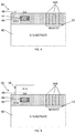
- FIG. 8A is a schematic, cross-sectional view showing light coupling of the III-V light source and the waveguide of the structure of FIG. 7 ;
- FIG. 8B is a top view showing light coupling of the III-V light source and the waveguide of the structure of FIG. 7 ;
- FIG. 9 is a schematic, cross-sectional view showing an integrated waveguide and light source in accordance with the prior art.
- a structure 40 including a bulk semiconductor substrate 42 , a dielectric layer 46 , and an embedded waveguide core 44 is shown in FIG. 1 .
- the substrate may be in the form of a crystalline silicon wafer that is essentially undoped.
- Dielectric layers are deposited sequentially on the substrate and subjected to lithographic processes to form, for example, a buried silicon nitride waveguide core 44 within a silicon dioxide layer 46 .
- Etch selectivity of SiN over SiO 2 allows the selective etching of a silicon nitride layer to form the waveguide core 44 .
- PECVD plasma enhanced chemical vapor deposition
- PECVD may also be employed for forming the silicon nitride layer as a blanket layer on the silicon dioxide layer.
- the silicon nitride deposited has the formula Si 3 N 4 in some embodiments and has uniform optical properties.
- the thickness of the silicon nitride layer is uniform and corresponds to the desired thickness of the waveguide(s) formed later in the process. In some embodiments, the thickness of the silicon nitride layer is between about one hundred to five hundred nanometers (100-500 nm). This thickness range should be considered exemplary as opposed to limiting. In one embodiment, the thickness of the silicon nitride layer is about two hundred nanometers.
- the silicon nitride layer may be planarized following deposition using a chemical mechanical planarization process.
- a patterned mask is formed on the silicon nitride layer.
- the exposed portions of the silicon nitride layer are removed, leaving only the waveguide core(s) 44 on the silicon dioxide layer 46 .
- Silicon nitride can be selectively removed either by wet etch (e.g., aqueous solution containing phosphoric acid) or dry etch (e.g., a plasma containing CH 3 F and O 2 ).
- the width of the silicon nitride waveguide core is between about one hundred and five hundred nanometers (100-500 nm) in some embodiments.
- Gratings (not shown in FIG.
- silicon dioxide is deposited over the waveguide core 44 , thereby encapsulating the silicon nitride core in a silicon dioxide (cladding) layer. Silicon nitride and silicon dioxide have different refractive indices allows the confinement of light within the resulting waveguide. The top surface of the deposited silicon dioxide material is planarized to obtain the structure 40 shown in FIG. 1 .
- a top semiconductor device layer 48 is formed on the top surface of the silicon dioxide layer 46 to obtain a structure 50 as shown in FIG. 2 .
- Germanium has a lattice constant that is essentially the same as that of gallium arsenide (GaAs) and is employed as the top device layer in exemplary embodiments. It can accordingly be used as a base layer for integration of GaAs-based devices.
- the germanium deposition process may employ the deposition chamber of a chemical vapor deposition type apparatus, such as a low pressure chemical vapor deposition (LPCVD) or a metalorganic chemical vapor deposition (MOCVD) apparatus.
- LPCVD low pressure chemical vapor deposition
- MOCVD metalorganic chemical vapor deposition
- a germanium gas source may, for example, be selected from the group consisting of germane, digermane, halogermane, dichlorogermane, trichlorogermane, tetrachlorogermane and combinations thereof.
- the temperature for epitaxial germanium deposition typically ranges from 450° C. to 900° C.
- the germanium device layer 48 is transferred to the silicon dioxide layer 46 from a bulk crystalline host (not shown) using known layer transfer techniques such as SMART CUT®. In these techniques, a thin layer of crystalline semiconductor is transferred from a host substrate and bonded onto an insulating handle (carrier) substrate. The transfer and/or bonding methods are different in different layer transfer techniques.
- One method of forming a GeOI substrate using the SMART CUT® method and wafer bonding involves bonding two semiconductor substrates with silicon oxide surface layers. The two wafers are bonded together at the silicon oxide surfaces to form a BOX layer between the two semiconductor substrates.
- the silicon dioxide layer 46 between the germanium and silicon layers 48 , 42 forms the BOX layer of the structure 50 shown in FIG. 2 .
- U.S. Pat. No. 5,374,564 which is incorporated by reference herein, discloses an exemplary layer forming and transfer process.
- U.S. Pat. No. 6,326,285, also incorporated by reference herein discloses techniques for semiconductor on insulator fabrication, including hydrogen implantation, wafer bonding, and cleaving along the hydrogen layer. Alternately. a thinned device wafer can be created by controlled spalling technology and subsequent layer transfer. Exemplary controlled spalling technology for forming device wafers is disclosed in U.S. Pat. No. 8,841,203, which is incorporated by reference herein.
- a further option for incorporating the germanium layer 48 includes epitaxially growing a germanium (Ge) layer on a Si substrate with a silicon germanium (SiGe) buffer layer (Ge/SiGe/Si) as the source of single crystalline Ge to be transferred and later patterned to form a semiconductor device layer.
- a SMART CUT or controlled spalling process is employed to separate a Ge layer of desired thickness from the Ge/SiGe/Si structure and transfer this top Ge layer to another Si substrate having an oxide layer (SiO2/Si) (such as shown in FIG. 1 ) to form the GeOI template shown in FIG. 2 on which III-V layers can later be grown.
- Germanium grown on silicon with a thick SiGe gradient buffer layer has sufficiently high quality to enable forming optoelectronic light emission devices thereon.
- the advantage of this approach is to use a high mechanical strength, large size Si substrate, having, for example, a diameter of twelve inches or even larger. Single crystal Ge substrates are not presently available for this large size.
- the Ge layer is first bonded to SiO 2 /Si substrate 40 and then separated from its host substrate. The process is similar to the SMART CUT process that is often used to form semiconductor-on-insulator (SOI) substrates.
- SOI semiconductor-on-insulator
- the Ge layer employed as the top semiconductor device layer is crystalline, and preferably essentially mono-crystalline.
- the germanium layer may have a thickness between about twenty and one hundred nanometers (20-100 nm). If necessary, a silicon germanium or a III-V layer can be used to form the semiconductor device layer 48 instead of germanium.
- the germanium layer 48 employed in the exemplary embodiment is patterned such that the remaining portion of the germanium layer is directly above the waveguide.
- Germanium may be etched selectively with respect to dielectric materials such as silicon dioxide by using a dry etch process (e.g. a plasma containing CF 4 and O 2 ) or a wet etch process (e.g. a solution containing hydrochloric acid).
- the remaining portion of the germanium layer above the waveguide core 44 has predetermined dimensions and is configured to correspond to those of a III-V optoelectronic light emitting device to be formed thereon by the selective deposition of III-V semiconductor layers.
- the germanium layer is patterned using photolithographic techniques to include tapered end portions having converging edges.
- the region of the patterned germanium layer between such tapered end portions may include parallel edges.
- the silicon dioxide layer 46 is then recessed down to the top surface of the substrate 42 in regions to be employed for MOSFET 52 or other electronic device fabrication.
- the waveguide region is protected by a mask (not shown) during a reactive ion etch to form the recess(es) 51 in the silicon dioxide layer.
- MOSFETs Metal oxide semiconductor field-effect transistors
- MOSFETs include gate electrodes that are electrically insulated from operatively associated semiconductor channels by thin layers of dielectric material. MOSFETs having n-doped source and drain regions employ electrons as the primary current carriers while those having p-doped source and drain regions use holes as primary current carriers.
- the formation of MOSFETs on silicon substrates is known to the art and continues to be developed.
- a structure 55 including a waveguide on a first lateral region of a semiconductor substrate and a MOSFET 52 on a second lateral region of the semiconductor substrate 42 is obtained at this stage of the fabrication process.
- the semiconductor device layer 48 obtained following patterning of the originally formed semiconductor (e.g. germanium) layer is entirely above the first lateral (waveguide) region of the semiconductor substrate.
- Silicon dioxide is deposited on the structure 55 using, for example, chemical vapor deposition.
- the silicon dioxide fills the recess 51 , thereby covering the MOSFET 52 . It also adjoins the exposed vertical surface of the silicon dioxide layer 46 encapsulating the waveguide core 44 .
- the top surface of the deposited material is then planarized.
- the silicon dioxide layer formed by the originally deposited material and the material later deposited to fill the recess 51 forms an integral layer designated by numeral 46 in FIG. 4 .
- Via conductors 54 A are formed within the silicon dioxide layer and are electrically connected to gate, source and drain regions of the MOSFET 52 . Via openings within the silicon dioxide layer 46 may be formed using photolithography and etch processes.
- the via openings are filled with an electrically conductive material such as a metal to provide a first set of via conductors 54 A.
- the electrically conductive material may be deposited using a physical vapor deposition (PVD) process such as plating or sputtering.
- PVD physical vapor deposition
- FIG. 4 schematically illustrates a monolithic structure 60 obtained at this stage of the fabrication process.
- a stack 56 of III-V semiconductor materials is epitaxially grown on the top surface of the germanium layer 48 .
- the stack 56 includes III-V layers used to form an optoelectronic light emission device.
- epitaxial growth and/or deposition and “epitaxially formed and/or grown” mean the growth of a semiconductor material (crystalline material) on a deposition surface of another semiconductor material (crystalline material), in which the semiconductor material being grown has substantially the same crystalline characteristics as the semiconductor material of the deposition surface (seed material).
- an epitaxially grown semiconductor material has substantially the same crystalline characteristics as the deposition surface on which the epitaxially grown material is formed. Growth of the III-V stack is selective to the germanium layer or other underlying semiconductor layer on which each III-V layer is grown. The III-V stack will accordingly have essentially the same dimensions and configuration as the patterned germanium layer 48 on which it is grown.
- the III-V semiconductor stack 56 grown on the germanium device layer 48 may include a buffer layer such as InGaP, GaAs, or other compound semiconductor material depending on the material employed to form the stack 56 .
- a buffer layer such as InGaP, GaAs, or other compound semiconductor material depending on the material employed to form the stack 56 .
- Such a buffer layer would have a lattice dimension between the lattice dimension of the germanium layer 48 comprising the base semiconductor substrate and the base layer of III-V semiconductor material for the optoelectronic light emission device formed from subsequently deposited III-V layers.
- the buffer layer reduces defects and undesired stresses in the layers comprising the optoelectronic light emission device.
- the first layer that provides the base of the optoelectronic light emission device may be formed.
- a III-V semiconductor material layer having a first conductivity type is formed using an epitaxial deposition process.
- the first III-V semiconductor layer may have n-type conductivity.
- the first III-V semiconductor material layer may have p-type conductivity.
- the dopant may be introduced via ion implantation or in situ. By “in situ” it is meant that the dopant that dictates the conductivity type of the doped layer is introduced during the process step, e.g., epitaxial deposition, that forms the doped layer.
- the effect of the dopant atom depends occupied by the site occupied by the dopant atom on the lattice of the base material.
- atoms from group II act as acceptors, i.e., p-type, when occupying the site of a group III atom
- atoms in group VI act as donors, i.e., n-type, when they replace atoms from group V.
- Dopant atoms from group IV such a silicon (Si)
- Such impurities are known as amphoteric impurities.
- III-V compound semiconductors are obtained by combining group III elements (for example, Al, Ga, In) with group V elements (for example, N, P, As, Sb).
- group III elements for example, Al, Ga, In
- group V elements for example, N, P, As, Sb
- GaAs, InGaAs, InP, GaP, and GaN are examples of III-V compound semiconductors.
- GaAs is epitaxially grown on the essentially defect-free top portion of the germanium (Ge) layer 48 .
- GaAs and Ge have essentially the same lattice constant, strain-induced defects are avoided in this embodiment and a buffer layer is not required.
- Various processes are familiar to those of skill in the art for epitaxially growing III-V semiconductor materials on semiconductor substrates such as germanium substrates.
- III-V semiconductor materials such processes include metalorganic chemical vapor deposition (MOCVD) and molecular beam epitaxy (MBE).
- MOCVD metalorganic chemical vapor deposition
- MBE molecular beam epitaxy
- Many different III-V compounds could be grown on the germanium layer 48 (or buffer layer thereon) depending upon the lattice constants of the III-V material and the goal of avoiding strain-induced epitaxial defects. Accordingly multiple precursors could be used. Depending on which III-V materials are to be grown and which precursors are used, different parameters (temperature, process pressure, times, etc.) are applicable.
- Metalorganic precursors include Trimethylgallium, Trimethylaluminum, Trimethylindium, Trimethylantimony, Tertiarybutylarsine and Tertiarybutylphosphine.
- Alternate Group V precursors include arsine and phosphine.
- process temperature, gas flow, pressure and times vary significantly.
- process parameters for growing III-V semiconductor materials on germanium and on other semiconductor materials are well known in the art and new methods continue to be developed.
- the first III-V semiconductor layer of the optoelectronic light emission device is typically grown to a thickness ranging from one micron to two microns (1-2 ⁇ m).
- the layers of a III-V multiple quantum well layered stack may be epitaxially formed on the first III-V semiconductor layer.
- the III-V multiple quantum well layered stack may include a layered stack of intrinsic III-V semiconductor materials.
- the epitaxial deposition process for forming the III-V multiple quantum well layered stack may be a selective epitaxial deposition process wherein the III-V semiconductor material only on forms on the exposed semiconductor surfaces, such as the upper surface of the first conductivity type III-V semiconductor material layer of the optoelectronic light emission device and is not formed on dielectric surfaces.
- the different compositions of the III-V multiple quantum well layered stack may be provided by changing and cycling the precursor gases used in growing the different layers comprising the III-V multiple quantum well layered stack.
- a second III-V semiconductor layer having a second conductivity type is epitaxially formed on a top surface of the III-V multiple quantum well layered stack.
- the second conductivity type is opposite to the first conductivity type.
- the first doped III-V semiconductor layer of the stack 56 has n-type conductivity
- the second doped III-V semiconductor layer at the top of the stack 56 has p-type conductivity.
- the III-V stack may be planarized, e.g., processed with chemical mechanical planarization.
- the structure 70 illustrated in FIG. 6 includes a completed optoelectronic light emission device 62 following patterning of the III-V stack 56 to expose portions of the doped III-V layer adjoining the germanium layer 48 on which it is directly or indirectly grown. Such patterning can be performed using photolithographic and anisotropic etching techniques known to the art. Metal contacts (not shown) can then be formed on the doped III-V layers of the optoelectronic light emission device by a physical vapor deposition (PVD) method such as sputtering or plating.
- PVD physical vapor deposition
- the exemplary optoelectronic light emission device 62 depicted in FIG. 6 may be a quantum well laser in which the wavelength of the light emitted by the quantum well laser is determined by the width of the active region rather than just the bandgap of the material from which it is constructed.
- the first and second III-V semiconductor material layers which may also be referred to as cladding layers, are doped to have opposite conductivity types.
- the doped III-V semiconductor layers function to pump charge carriers, i.e., electron and hole charge carriers, into the intrinsic active area provided by the quantum well.
- the doped first and second III-V semiconductor layers may be composed of InP, GaAs, AlGaAs, InAlAs or a combination thereof.
- the dopants that provide the conductivity types of the first and second III-V semiconductor layers of the device may be present in a concentration ranging from 10 17 atoms/cm 3 to 10 20 atoms/cm 3 .
- the first (bottom) III-V semiconductor layer may have a thickness ranging from 100 nm to 2,000 nm.
- the second (top) doped III-V semiconductor layer may be composed of InP, GaAs, AlGaAs or InAlAs.
- the second (top) III-V semiconductor layer of the device may have a thickness ranging from 100 nm to 2,000 nm.
- the active region of the laser diode is in the intrinsic (I) region.
- intrinsic it is meant that the region is not doped with an extrinsic dopant, e.g., n-type or p-type dopant, such as the dopants within the first and second III-V semiconductor material layers of the III-V stack 56 .
- the “intrinsic” III-V layers may include some unintentional doping resulting from diffusion of dopant ions from the doped III-V layers.
- the active region in the quantum well structure is formed by alternating layers of relatively low bandgap material and layers of relatively high bandgap material.
- a “low bandgap” is a bandgap ranging from 0.5 eV to 3.0 eV; a “high bandgap” ranges from 1.0 eV to 3.5 eV.
- the low bandgap layers are termed “well layers” and the high bandgap layers are termed “barrier layers.”
- the active low bandgap layers may comprise Al r Ga 1-r As and the passive high bandgap layers may comprise Al z Ga 1-z As with r ⁇ z.
- each layer of III-V compound semiconductor material within the quantum well is preferably no greater than about 50 nm, and is for example between five and ten nanometers (5-10 nm) in some embodiments.
- the stacked structure of quantum wells may, for example, include up to one hundred layers. In some embodiments, the stacked structure of quantum wells is composed of five layers or less of semiconductor material.
- the quantum well (QW) layers and barrier layers of the quantum well structure may be formed, for example, of In x Ga 1-x As y P 1-y , In x Ga 1-x As, In x Ga 1-x N y As 1-y , In x Ga 1-x As y Sb (where, 0.0 ⁇ x ⁇ 1.0, 0.0 ⁇ y ⁇ 1.0).
- the optoelectronic light emission device 62 may have a width ranging from three (3) microns to five (5) microns.
- the width dimension of the optoelectronic light emission device 62 is along a dimension perpendicular to the direction along which the optoelectronic light emission device 62 emits a beam of light. In some embodiments, the width may range from 2.75 microns to 4.25 microns, and in one example is equal to 4 microns.
- the length of the optoelectronic light emission device 62 may range from approximately 50 microns to approximately 300 microns. In one example, the length of the optoelectronic light emission device 62 may be approximately 80 microns.
- the waveguide core 44 is between two hundred and two thousand nanometers (200-2,000 nm) from the top surface of the silicon dioxide layer 46 on which the germanium layer 48 is formed.
- the distance between the waveguide core 44 and the optoelectronic light emission device 62 is within a distance comparable to the wavelength of the light to be emitted by the device in some embodiments.
- a second dielectric layer 46 ′ is formed over the bottom dielectric layer 46 .
- the second dielectric layer may, like the underlying dielectric layer, also consist essentially of silicon dioxide.
- the optoelectronic light emission device 62 is encapsulated by the second dielectric layer 46 ′.
- Via conductors 54 B are formed within the second dielectric layer. Some of the via conductors are electrically connected to the doped bottom and top layers of the optoelectronic light emission device 62 while others are electrically connected to the via conductors 54 A in the bottom silicon dioxide layer 46 .
- FIG. 7 shows the structure 75 following formation of the second metallized layer.
- FIGS. 8A and 8B further schematically illustrate the arrangement of the optically coupled optoelectronic light emission device 62 and waveguide core 44 .
- the waveguide core 44 includes gratings 44 ′ therein to facilitate light coupling.
- the portion of the waveguide core 44 directly beneath the optoelectronic light emission device 62 has a planar top surface.
- the end portions 62 ′ of the optoelectronic light emission device 62 and underlying semiconductor (e.g. Ge) device layer are tapered to further facilitate light coupling.
- the optoelectronic light emission device 62 and the semiconductor device layer 48 on which it is grown have longitudinal axes parallel to the longitudinal axis of the waveguide core 44 , as best shown in FIG. 8B .
- Electronic devices comprising the III-V optoelectronic device and associated waveguide may be incorporated within electronic circuitry that, in one or more exemplary embodiments, comprises an integrated circuit (IC).
- the electronic circuitry may include an assembly of electronic components, fabricated as a monolithic unit, in which active and passive devices and their interconnections are formed.
- the resulting circuit may perform one or more functions (e.g. logic, memory, sensing) depending on the arrangement of the components.
- Semiconductor device manufacturing includes various steps of device patterning processes.
- the manufacturing of a semiconductor chip may start with, for example, a plurality of CAD (computer aided design) generated device patterns, which is then followed by effort to replicate these device patterns in a substrate.
- the replication process may involve the use of various exposing techniques and a variety of subtractive (etching) and/or additive (deposition) material processing procedures.
- etching subtractive
- deposition additive
- Portions of the photo-resist that are exposed to light or other ionizing radiation may experience some changes in their solubility to certain solutions.
- the photo-resist may then be developed in a developer solution, thereby removing the non-irradiated (in a negative resist) or irradiated (in a positive resist) portions of the resist layer, to create a photo-resist pattern or photo-mask.
- the photo-resist pattern or photo-mask may subsequently be copied or transferred to the substrate underneath the photo-resist pattern.
- etching includes techniques of wet etching, dry etching, chemical oxide removal (COR) etching, and reactive ion etching (RIE), which are all known techniques to remove select material when forming a semiconductor structure.
- COR chemical oxide removal
- RIE reactive ion etching
- an exemplary method of fabricating a an optoelectronic device includes obtaining a first structure including a semiconductor substrate 42 including a first region and a second region, the second region being laterally displaced from the first region, a bottom dielectric layer 46 on the semiconductor substrate, and a buried waveguide core 44 within the bottom dielectric layer and directly above the first region of the semiconductor substrate.
- FIG. 1 schematically illustrates an exemplary first structure 40 .
- a semiconductor layer 48 such as a germanium layer is formed on the bottom dielectric layer 46 to obtain a structure 50 as exemplified in FIG. 2 .
- a recess 51 is formed within the bottom dielectric layer over the second region of the semiconductor substrate 42 and a field-effect transistor is formed in the second region of the semiconductor substrate 42 , thereby obtaining the exemplary structure 55 as shown in FIG. 3 .
- the recess 51 is filled with dielectric material and first electrical conductors 54 A are formed within the dielectric material, the first electrical conductors being electrically connected to the field-effect transistor 52 as schematically illustrated in FIG. 4 .
- a stack 56 of epitaxial III-V semiconductor layers is selectively grown on the device layer over the first region of the semiconductor substrate and comprises an optoelectronic structure configured for light emission.
- the optoelectronic structure is patterned to obtain a structure 70 as schematically illustrated in FIG. 6 .
- a top dielectric layer 46 ′ is formed over the bottom dielectric layer 46 and the dielectric material filling the recess 51 .
- the top dielectric layer 46 ′ encapsulates the optoelectronic structure 62 formed from the stack of III-V semiconductor layers.
- Second electrical conductors 54 B are formed within the top dielectric layer 46 ′ and are electrically connected to the first electrical conductors and the optoelectronic structure 62 as shown in FIG. 7 .
- the buried waveguide core 44 may be a dielectric waveguide core extending directly beneath the optoelectronic structure 62 .
- the buried waveguide core consists essentially of silicon nitride and the semiconductor layer consists essentially of germanium.
- a germanium layer is obtained in some embodiments by epitaxially growing a graded silicon germanium layer on a silicon base. The silicon germanium layer has an increasing germanium content as the silicon germanium layer is grown to facilitate lattice matching of the subsequently grown germanium layer. An essentially monocrystalline germanium layer is epitaxially grown on the silicon germanium layer.
- the germanium layer is transferred to the structure 40 shown in FIG. 1 using a selected layer transfer technique and bonded to the dielectric layer 46 .
- the transferred layer includes at least a surface portion that consists essentially of germanium to facilitate subsequent growth of III-V semiconductor layers thereon.
- a semiconductor substrate 42 includes a first region and a second region, the second region being laterally displaced from the first region.
- a bottom dielectric layer 46 is on the semiconductor substrate 42 .
- a buried waveguide core 44 is within the bottom dielectric layer and is located directly above the first region of the semiconductor substrate.
- a germanium layer 48 is on a top surface of the bottom dielectric layer and is positioned above the waveguide core 44 .
- a field-effect transistor 52 is in the second region of the semiconductor substrate and located beneath the bottom dielectric layer 46 .
- First electrical conductors 54 A are electrically connected to the field-effect transistor.
- the monolithic optoelectronic structure further includes an optoelectronic light emission device 62 comprising a plurality of epitaxial III-V semiconductor layers on the germanium layer.
- a top dielectric layer 46 ′ encapsulates the optoelectronic light emission device 62 .
- Second electrical conductors 54 B within the top dielectric layer 46 ′ are electrically connected to the first electrical conductors 54 A and to the optoelectronic light emission device 62 .
- the III-V semiconductor layers comprise a quantum well in some embodiments.
- At least a portion of the techniques described above may be implemented in an integrated circuit.
- identical dies are typically fabricated in a repeated pattern on a surface of a semiconductor wafer.
- Each die includes a device described herein, and may include other structures and/or circuits.
- the individual dies are cut or diced from the wafer, then packaged as an integrated circuit.
- One skilled in the art would know how to dice wafers and package die to produce integrated circuits. Any of the exemplary circuits illustrated in the accompanying figures, or portions thereof, may be part of an integrated circuit. Integrated circuits so manufactured are considered part of this disclosure.
- exemplary structures discussed above can be distributed in raw form (i.e., a single wafer having multiple unpackaged chips), as bare dies, in packaged form, or incorporated as parts of intermediate products or end products that benefit from having optoelectronic or other devices therein.
- An integrated circuit in accordance with aspects of the present disclosure can be employed in essentially any application and/or electronic system where the use of optoelectronic devices would be beneficial. Given the teachings of the present disclosure provided herein, one of ordinary skill in the art will be able to contemplate other implementations and applications of embodiments disclosed herein.
- Embodiments are referred to herein, individually and/or collectively, by the term “embodiment” merely for convenience and without intending to limit the scope of this application to any single embodiment or inventive concept if more than one is, in fact, shown.
- the term “embodiment” merely for convenience and without intending to limit the scope of this application to any single embodiment or inventive concept if more than one is, in fact, shown.
- this disclosure is intended to cover any and all adaptations or variations of various embodiments. Combinations of the above embodiments, and other embodiments not specifically described herein, will become apparent to those of skill in the art given the teachings herein.
Landscapes
- Physics & Mathematics (AREA)
- Engineering & Computer Science (AREA)
- General Physics & Mathematics (AREA)
- Optics & Photonics (AREA)
- Microelectronics & Electronic Packaging (AREA)
- Power Engineering (AREA)
- Optical Integrated Circuits (AREA)
Abstract
Description
Claims (10)
Priority Applications (1)
| Application Number | Priority Date | Filing Date | Title |
|---|---|---|---|
| US16/016,653 US10690853B2 (en) | 2018-06-25 | 2018-06-25 | Optoelectronics integration using semiconductor on insulator substrate |
Applications Claiming Priority (1)
| Application Number | Priority Date | Filing Date | Title |
|---|---|---|---|
| US16/016,653 US10690853B2 (en) | 2018-06-25 | 2018-06-25 | Optoelectronics integration using semiconductor on insulator substrate |
Publications (2)
| Publication Number | Publication Date |
|---|---|
| US20190391328A1 US20190391328A1 (en) | 2019-12-26 |
| US10690853B2 true US10690853B2 (en) | 2020-06-23 |
Family
ID=68981620
Family Applications (1)
| Application Number | Title | Priority Date | Filing Date |
|---|---|---|---|
| US16/016,653 Expired - Fee Related US10690853B2 (en) | 2018-06-25 | 2018-06-25 | Optoelectronics integration using semiconductor on insulator substrate |
Country Status (1)
| Country | Link |
|---|---|
| US (1) | US10690853B2 (en) |
Cited By (2)
| Publication number | Priority date | Publication date | Assignee | Title |
|---|---|---|---|---|
| US20230105346A1 (en) * | 2021-10-05 | 2023-04-06 | Commissariat à l'Energie Atomique et aux Energies Alternatives | Photonic chip |
| US20240085610A1 (en) * | 2022-09-13 | 2024-03-14 | Taiwan Semiconductor Manufacturing Co., Ltd. | Photonic Package and Method of Manufacture |
Families Citing this family (15)
| Publication number | Priority date | Publication date | Assignee | Title |
|---|---|---|---|---|
| GB2552264B (en) | 2016-07-13 | 2021-06-02 | Rockley Photonics Ltd | Integrated structure and manufacturing method thereof |
| CA3047133A1 (en) | 2016-12-16 | 2018-06-21 | Quantum-Si Incorporated | Compact mode-locked laser module |
| CN116466494A (en) | 2016-12-16 | 2023-07-21 | 宽腾矽公司 | Compact beam shaping and steering assembly |
| CA3100987A1 (en) | 2018-06-15 | 2019-12-19 | Quantum-Si Incorporated | Data acquisition control for advanced analytic instruments having pulsed optical sources |
| EP4411347A3 (en) * | 2019-06-14 | 2024-10-30 | Quantum-Si Incorporated | Sliced grating coupler with increased beam alignment sensitivity |
| US10983412B1 (en) * | 2019-11-05 | 2021-04-20 | Globalfoundries U.S. Inc. | Silicon photonic components fabricated using a bulk substrate |
| US11381053B2 (en) * | 2019-12-18 | 2022-07-05 | Globalfoundries U.S. Inc. | Waveguide-confining layer with gain medium to emit subwavelength lasers, and method to form same |
| US11349280B2 (en) | 2020-01-10 | 2022-05-31 | Newport Fab, Llc | Semiconductor structure having group III-V device on group IV substrate |
| US11581452B2 (en) * | 2020-01-10 | 2023-02-14 | Newport Fab, Llc | Semiconductor structure having group III-V device on group IV substrate and contacts with precursor stacks |
| US11929442B2 (en) | 2020-01-10 | 2024-03-12 | Newport Fab, Llc | Structure and method for process control monitoring for group III-V devices integrated with group IV substrate |
| US11296482B2 (en) | 2020-01-10 | 2022-04-05 | Newport Fab, Llc | Semiconductor structure having group III-V chiplet on group IV substrate and cavity in proximity to heating element |
| US11545587B2 (en) | 2020-01-10 | 2023-01-03 | Newport Fab, Llc | Semiconductor structure having group III-V device on group IV substrate and contacts with liner stacks |
| CN115210969A (en) | 2020-01-14 | 2022-10-18 | 宽腾矽公司 | Amplitude-modulated laser |
| US11199672B1 (en) * | 2020-06-15 | 2021-12-14 | Globalfoundries U.S. Inc. | Multiple waveguide coupling to one or more photodetectors |
| US12276831B2 (en) * | 2022-11-28 | 2025-04-15 | Globalfoundries U.S. Inc. | Enlarged multilayer nitride waveguide for photonic integrated circuit |
Citations (21)
| Publication number | Priority date | Publication date | Assignee | Title |
|---|---|---|---|---|
| US20060281232A1 (en) * | 2005-06-10 | 2006-12-14 | Sharp Laboratories Of America, Inc. | Method of growing a germanium epitaxial film on insulator for use in fabrication of a CMOS integrated circuit |
| US20070010066A1 (en) * | 2005-07-07 | 2007-01-11 | Oki Electric Industry Co., Ltd. | Method for manufacturing semiconductor device |
| US20070217750A1 (en) | 2006-03-14 | 2007-09-20 | International Business Machines Corporation | Interconnecting (mapping) a two-dimensional optoelectronic (OE) device array to a one-dimensional waveguide array |
| US7547914B2 (en) | 2006-01-17 | 2009-06-16 | Stmicroelectronics (Crolles 2) Sas | Single-crystal layer on a dielectric layer |
| US7705370B2 (en) | 2005-11-01 | 2010-04-27 | Massachusetts Institute Of Technology | Monolithically integrated photodetectors |
| US7749817B2 (en) | 2006-01-17 | 2010-07-06 | Stmicroelectronics (Crolles) Sas | Single-crystal layer on a dielectric layer |
| CN102437129A (en) | 2011-08-29 | 2012-05-02 | 上海华力微电子有限公司 | Localized SOI (Silicon-On-Insulator) and GOI (Germanium On Insulator) device structure and process integrating method thereof |
| US8664739B2 (en) | 2002-12-18 | 2014-03-04 | Infrared Newco, Inc. | Image sensor comprising isolated germanium photodetectors integrated with a silicon substrate and silicon circuitry |
| US8741684B2 (en) | 2011-05-09 | 2014-06-03 | Imec | Co-integration of photonic devices on a silicon photonics platform |
| US20150030047A1 (en) | 2013-07-24 | 2015-01-29 | International Business Machines Corporation | Iii-v lasers with integrated silicon photonic circuits |
| US9040391B2 (en) | 2008-08-22 | 2015-05-26 | Commissariat A L'energie Atomique | Process for producing localised GeOI structures, obtained by germanium condensation |
| US20150249212A1 (en) | 2014-02-28 | 2015-09-03 | International Business Machines Corporation | Optoelectronics integration by transfer process |
| US20150333481A1 (en) | 2013-07-01 | 2015-11-19 | Universiteit Gent | Hybrid Waveguide Lasers and Methods for Fabricating Hybrid Waveguide Lasers |
| US20160252677A1 (en) | 2014-10-08 | 2016-09-01 | International Business Machines Corporation | Complementary metal oxide semiconductor device with iii-v optical interconnect having iii-v epitaxially formed material |
| US20160276330A1 (en) | 2015-03-18 | 2016-09-22 | International Business Machines Corporation | Optoelectronics and cmos integration on goi substrate |
| US20160293801A1 (en) | 2015-04-01 | 2016-10-06 | International Business Machines Corporation | Optoelectronic devices with back contact |
| US20170123150A1 (en) | 2015-10-28 | 2017-05-04 | International Business Machines Corporation | Integration of bonded optoelectronics, photonics waveguide and vlsi soi |
| US20170170632A1 (en) | 2015-12-11 | 2017-06-15 | International Business Machines Corporation | Small aperture formation for facilitating optoelectronic device integration with defective semiconductor materials |
| US20170179681A1 (en) | 2015-12-18 | 2017-06-22 | International Business Machines Corporation | Semiconductor optoelectronics and cmos on sapphire substrate |
| US20180323123A1 (en) | 2017-05-04 | 2018-11-08 | International Business Machines Corporation | Thiourea organic compound for gallium arsenide based optoelectronics surface passivation |
| US20190134420A1 (en) | 2017-11-09 | 2019-05-09 | International Business Machines Corporation | Cognitive optogenetics probe and analysis |
-
2018
- 2018-06-25 US US16/016,653 patent/US10690853B2/en not_active Expired - Fee Related
Patent Citations (36)
| Publication number | Priority date | Publication date | Assignee | Title |
|---|---|---|---|---|
| US9142585B2 (en) | 2002-12-18 | 2015-09-22 | Infrared Newco, Inc. | Image sensor comprising isolated germanium photodetectors integrated with a silicon substrate and silicon circuitry |
| US20150364515A1 (en) | 2002-12-18 | 2015-12-17 | Infrared Newco, Inc. | Image sensor comprising isolated germanium photodetectors integrated with a silicon substrate and silicon circuitry |
| US8664739B2 (en) | 2002-12-18 | 2014-03-04 | Infrared Newco, Inc. | Image sensor comprising isolated germanium photodetectors integrated with a silicon substrate and silicon circuitry |
| US20060281232A1 (en) * | 2005-06-10 | 2006-12-14 | Sharp Laboratories Of America, Inc. | Method of growing a germanium epitaxial film on insulator for use in fabrication of a CMOS integrated circuit |
| US20070010066A1 (en) * | 2005-07-07 | 2007-01-11 | Oki Electric Industry Co., Ltd. | Method for manufacturing semiconductor device |
| US8012592B2 (en) | 2005-11-01 | 2011-09-06 | Massachuesetts Institute Of Technology | Monolithically integrated semiconductor materials and devices |
| US8120060B2 (en) | 2005-11-01 | 2012-02-21 | Massachusetts Institute Of Technology | Monolithically integrated silicon and III-V electronics |
| US7705370B2 (en) | 2005-11-01 | 2010-04-27 | Massachusetts Institute Of Technology | Monolithically integrated photodetectors |
| US7749817B2 (en) | 2006-01-17 | 2010-07-06 | Stmicroelectronics (Crolles) Sas | Single-crystal layer on a dielectric layer |
| US7547914B2 (en) | 2006-01-17 | 2009-06-16 | Stmicroelectronics (Crolles 2) Sas | Single-crystal layer on a dielectric layer |
| US20070217750A1 (en) | 2006-03-14 | 2007-09-20 | International Business Machines Corporation | Interconnecting (mapping) a two-dimensional optoelectronic (OE) device array to a one-dimensional waveguide array |
| US9040391B2 (en) | 2008-08-22 | 2015-05-26 | Commissariat A L'energie Atomique | Process for producing localised GeOI structures, obtained by germanium condensation |
| US8741684B2 (en) | 2011-05-09 | 2014-06-03 | Imec | Co-integration of photonic devices on a silicon photonics platform |
| CN102437129A (en) | 2011-08-29 | 2012-05-02 | 上海华力微电子有限公司 | Localized SOI (Silicon-On-Insulator) and GOI (Germanium On Insulator) device structure and process integrating method thereof |
| CN102437129B (en) | 2011-08-29 | 2014-09-03 | 上海华力微电子有限公司 | Localized SOI (Silicon-On-Insulator) and GOI (Germanium On Insulator) device structure and process integrating method thereof |
| US20150333481A1 (en) | 2013-07-01 | 2015-11-19 | Universiteit Gent | Hybrid Waveguide Lasers and Methods for Fabricating Hybrid Waveguide Lasers |
| US20150030047A1 (en) | 2013-07-24 | 2015-01-29 | International Business Machines Corporation | Iii-v lasers with integrated silicon photonic circuits |
| US20150249212A1 (en) | 2014-02-28 | 2015-09-03 | International Business Machines Corporation | Optoelectronics integration by transfer process |
| US20170018715A1 (en) | 2014-02-28 | 2017-01-19 | International Business Machines Corporation | Optoelectronics integration by transfer process |
| US20160252677A1 (en) | 2014-10-08 | 2016-09-01 | International Business Machines Corporation | Complementary metal oxide semiconductor device with iii-v optical interconnect having iii-v epitaxially formed material |
| US20160276330A1 (en) | 2015-03-18 | 2016-09-22 | International Business Machines Corporation | Optoelectronics and cmos integration on goi substrate |
| US20190221592A1 (en) | 2015-03-18 | 2019-07-18 | International Business Machines Corporation | Optoelectronics and cmos integration on goi substrate |
| US20190214413A1 (en) | 2015-03-18 | 2019-07-11 | International Business Machines Corporation | Optoelectronics and cmos integration on goi substrate |
| US20170141142A1 (en) | 2015-03-18 | 2017-05-18 | International Business Machines Corporation | Optoelectronics and cmos integration on goi substrate |
| US20170125457A1 (en) | 2015-04-01 | 2017-05-04 | International Business Machines Corporation | Optoelectronic devices with back contact |
| US20160293801A1 (en) | 2015-04-01 | 2016-10-06 | International Business Machines Corporation | Optoelectronic devices with back contact |
| US20170123151A1 (en) | 2015-10-28 | 2017-05-04 | International Business Machines Corporation | Integration of bonded optoelectronics, photonics waveguide and vlsi soi |
| US20170123152A1 (en) | 2015-10-28 | 2017-05-04 | International Business Machines Corporation | Integration of bonded optoelectronics, photonics waveguide and vlsi soi |
| US20170123153A1 (en) | 2015-10-28 | 2017-05-04 | International Business Machines Corporation | Integration of bonded optoelectronics, photonics waveguide and vlsi soi |
| US20180217329A1 (en) | 2015-10-28 | 2018-08-02 | International Business Machines Corporation | Integration of bonded optoelectronics, photonics waveguide and vlsi soi |
| US20170123168A1 (en) | 2015-10-28 | 2017-05-04 | International Business Machines Corporation | Integration of bonded optoelectronics, photonics waveguide and vlsi soi |
| US20170123150A1 (en) | 2015-10-28 | 2017-05-04 | International Business Machines Corporation | Integration of bonded optoelectronics, photonics waveguide and vlsi soi |
| US20170170632A1 (en) | 2015-12-11 | 2017-06-15 | International Business Machines Corporation | Small aperture formation for facilitating optoelectronic device integration with defective semiconductor materials |
| US20170179681A1 (en) | 2015-12-18 | 2017-06-22 | International Business Machines Corporation | Semiconductor optoelectronics and cmos on sapphire substrate |
| US20180323123A1 (en) | 2017-05-04 | 2018-11-08 | International Business Machines Corporation | Thiourea organic compound for gallium arsenide based optoelectronics surface passivation |
| US20190134420A1 (en) | 2017-11-09 | 2019-05-09 | International Business Machines Corporation | Cognitive optogenetics probe and analysis |
Non-Patent Citations (1)
| Title |
|---|
| ESPACENET, Bibliographic data and abstract of CN102437129(B). |
Cited By (3)
| Publication number | Priority date | Publication date | Assignee | Title |
|---|---|---|---|---|
| US20230105346A1 (en) * | 2021-10-05 | 2023-04-06 | Commissariat à l'Energie Atomique et aux Energies Alternatives | Photonic chip |
| US12222544B2 (en) * | 2021-10-05 | 2025-02-11 | Commissariat à l'Energie Atomique et aux Energies Alternatives | Photonic chip |
| US20240085610A1 (en) * | 2022-09-13 | 2024-03-14 | Taiwan Semiconductor Manufacturing Co., Ltd. | Photonic Package and Method of Manufacture |
Also Published As
| Publication number | Publication date |
|---|---|
| US20190391328A1 (en) | 2019-12-26 |
Similar Documents
| Publication | Publication Date | Title |
|---|---|---|
| US10690853B2 (en) | Optoelectronics integration using semiconductor on insulator substrate | |
| US11550099B2 (en) | Photonics optoelectrical system | |
| US9379204B2 (en) | Lattice matched aspect ratio trapping to reduce defects in III-V layer directly grown on silicon | |
| US11029466B2 (en) | Photonics structure with integrated laser | |
| JP6484076B2 (en) | Optical device | |
| US8120060B2 (en) | Monolithically integrated silicon and III-V electronics | |
| US11698488B2 (en) | Method for fabricating a heterostructure comprising active or passive elementary structure made of III-V material on the surface of a silicon-based substrate | |
| US9966735B2 (en) | III-V lasers with integrated silicon photonic circuits | |
| US12366705B2 (en) | Photonics optoelectrical system | |
| CN103094320A (en) | Semiconductor device including III-V compound semiconductor layer and manufacturing method thereof | |
| CN108054182B (en) | Compound semiconductor silicon-based hybrid device and preparation method thereof | |
| JP2024545854A (en) | Fabrication of semiconductor devices including quantum dot structures | |
| CN111987585B (en) | Silicon waveguide output laser | |
| US20230318263A1 (en) | Optoelectronic device comprising a iii-v semiconductor membrane laser source forming a lateral p-i-n junction | |
| US12353068B2 (en) | Method for on-silicon integration of a component III-V and on-silicon integrated component III-V | |
| JPH02266514A (en) | Semiconductor device in hetero structure and its manufacture | |
| US10559504B2 (en) | High mobility semiconductor fins on insulator | |
| JP7719575B2 (en) | Fabrication of semiconductor structures | |
| US12136682B2 (en) | Device integration using carrier wafer | |
| KR100359739B1 (en) | Method of fusion for heteroepitaxial layers and overgrowth thereon | |
| US20230395561A1 (en) | Method for Producing a Semiconductor Chip | |
| JP2017054859A (en) | Semiconductor light emitting device | |
| US10389090B2 (en) | Lateral growth of edge-emitting lasers | |
| WO2020237423A1 (en) | Laser having output silicon waveguide | |
| KR20120120129A (en) | Semiconductor substrate, semiconductor device, and production method for semiconductor substrate |
Legal Events
| Date | Code | Title | Description |
|---|---|---|---|
| AS | Assignment |
Owner name: INTERNATIONAL BUSINESS MACHINES CORPORATION, NEW Y Free format text: ASSIGNMENT OF ASSIGNORS INTEREST;ASSIGNORS:LI, NING;SADANA, DEVENDRA K.;REEL/FRAME:046186/0147 Effective date: 20180615 Owner name: INTERNATIONAL BUSINESS MACHINES CORPORATION, NEW YORK Free format text: ASSIGNMENT OF ASSIGNORS INTEREST;ASSIGNORS:LI, NING;SADANA, DEVENDRA K.;REEL/FRAME:046186/0147 Effective date: 20180615 |
|
| FEPP | Fee payment procedure |
Free format text: ENTITY STATUS SET TO UNDISCOUNTED (ORIGINAL EVENT CODE: BIG.); ENTITY STATUS OF PATENT OWNER: LARGE ENTITY |
|
| STPP | Information on status: patent application and granting procedure in general |
Free format text: NOTICE OF ALLOWANCE MAILED -- APPLICATION RECEIVED IN OFFICE OF PUBLICATIONS |
|
| AS | Assignment |
Owner name: INTERNATIONAL BUSINESS MACHINES CORPORATION, NEW YORK Free format text: ASSIGNMENT OF ASSIGNORS INTEREST;ASSIGNOR:HEIDELBERGER, CHRISTOPHER;REEL/FRAME:051575/0626 Effective date: 20200116 |
|
| STPP | Information on status: patent application and granting procedure in general |
Free format text: NOTICE OF ALLOWANCE MAILED -- APPLICATION RECEIVED IN OFFICE OF PUBLICATIONS |
|
| STPP | Information on status: patent application and granting procedure in general |
Free format text: PUBLICATIONS -- ISSUE FEE PAYMENT RECEIVED |
|
| STCF | Information on status: patent grant |
Free format text: PATENTED CASE |
|
| FEPP | Fee payment procedure |
Free format text: MAINTENANCE FEE REMINDER MAILED (ORIGINAL EVENT CODE: REM.); ENTITY STATUS OF PATENT OWNER: LARGE ENTITY |
|
| LAPS | Lapse for failure to pay maintenance fees |
Free format text: PATENT EXPIRED FOR FAILURE TO PAY MAINTENANCE FEES (ORIGINAL EVENT CODE: EXP.); ENTITY STATUS OF PATENT OWNER: LARGE ENTITY |
|
| STCH | Information on status: patent discontinuation |
Free format text: PATENT EXPIRED DUE TO NONPAYMENT OF MAINTENANCE FEES UNDER 37 CFR 1.362 |
|
| FP | Lapsed due to failure to pay maintenance fee |
Effective date: 20240623 |