US1069079A - Check for sliding doors. - Google Patents
Check for sliding doors. Download PDFInfo
- Publication number
- US1069079A US1069079A US1913742805A US1069079A US 1069079 A US1069079 A US 1069079A US 1913742805 A US1913742805 A US 1913742805A US 1069079 A US1069079 A US 1069079A
- Authority
- US
- United States
- Prior art keywords
- door
- movement
- pawl
- opening
- check
- Prior art date
- Legal status (The legal status is an assumption and is not a legal conclusion. Google has not performed a legal analysis and makes no representation as to the accuracy of the status listed.)
- Expired - Lifetime
Links
Images
Classifications
-
- E—FIXED CONSTRUCTIONS
- E05—LOCKS; KEYS; WINDOW OR DOOR FITTINGS; SAFES
- E05B—LOCKS; ACCESSORIES THEREFOR; HANDCUFFS
- E05B17/00—Accessories in connection with locks
- E05B17/0025—Devices for forcing the wing firmly against its seat or to initiate the opening of the wing
-
- E—FIXED CONSTRUCTIONS
- E05—LOCKS; KEYS; WINDOW OR DOOR FITTINGS; SAFES
- E05F—DEVICES FOR MOVING WINGS INTO OPEN OR CLOSED POSITION; CHECKS FOR WINGS; WING FITTINGS NOT OTHERWISE PROVIDED FOR, CONCERNED WITH THE FUNCTIONING OF THE WING
- E05F11/00—Man-operated mechanisms for operating wings, including those which also operate the fastening
-
- Y—GENERAL TAGGING OF NEW TECHNOLOGICAL DEVELOPMENTS; GENERAL TAGGING OF CROSS-SECTIONAL TECHNOLOGIES SPANNING OVER SEVERAL SECTIONS OF THE IPC; TECHNICAL SUBJECTS COVERED BY FORMER USPC CROSS-REFERENCE ART COLLECTIONS [XRACs] AND DIGESTS
- Y10—TECHNICAL SUBJECTS COVERED BY FORMER USPC
- Y10S—TECHNICAL SUBJECTS COVERED BY FORMER USPC CROSS-REFERENCE ART COLLECTIONS [XRACs] AND DIGESTS
- Y10S292/00—Closure fasteners
- Y10S292/46—Sliding door fasteners
-
- Y—GENERAL TAGGING OF NEW TECHNOLOGICAL DEVELOPMENTS; GENERAL TAGGING OF CROSS-SECTIONAL TECHNOLOGIES SPANNING OVER SEVERAL SECTIONS OF THE IPC; TECHNICAL SUBJECTS COVERED BY FORMER USPC CROSS-REFERENCE ART COLLECTIONS [XRACs] AND DIGESTS
- Y10—TECHNICAL SUBJECTS COVERED BY FORMER USPC
- Y10T—TECHNICAL SUBJECTS COVERED BY FORMER US CLASSIFICATION
- Y10T292/00—Closure fasteners
- Y10T292/08—Bolts
- Y10T292/1043—Swinging
Definitions
- This invention relates to a safety check or blocking device for sliding doors and more particularly used in connection with such doors when employed for elevator shafts.
- the present invention provides a simple yet eflective checking device which will yieldingly resist the attempted reopening of such a door during its closing movement, thus deterring personsoutside of the elevator shaft from forcing the door open while the same is in the act of closing, such preventive measures being particularly necessary when the door is closing and the elevator has started away from the lancling before the door has been fully closed.
- the improved check device forming the subject matter of the present invention is arranged to offer a resistance (which may be predetermined) to such opening of the door, but is adapted to yield to pressure greater than such predetermined resistance, so that the door may be forced open under such conditions.
- a resistance which may be predetermined
- Such opening pressure must perforce be comparatively great, but not so great as to be beyond attainment by an adult, such as the elevator operator.
- Such a device as described will enable the operator to leave his car at a landing with the well-door partially closed, but not latched from the interior.
- the door will be safe against ordinary opening effort on the part of an unauthorized person but is, nevertheless subject to opening through the efforts of the operator.
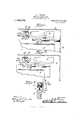
- Figure 1 is a fragmentary View of the top edge of a door and casing with my invention applied thereto, the door being shown in closed position.
- Fig. 2 is a similar View showing the door partially closed and the parts of the check ing device in a position to offer a yielding resistance to reopening movement.
- Fig. 3 is a similar View showing the door partially closed and the parts of the check ing device in a position to offer a yielding resistance to reopening movement.
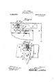
- Fig. 4 is a fragnentary view in elevation of the top of a door and casing with the checking parts in their forced position.
- F ig. 5 is a detail view in elevation and on an enlarged scale, of the pawl member of the checking device.
- 1 indicates a sliding door and 2 its casing.
- the door 1 is provided with suitable opening and closing mechanism. Any suitable means may also be provided to hold the door locked in closed position.
- the door l is mounted in any suitable manner to slide, as, for example, by supporting the same from an overhead track 3 by means of a hanger 4.
- the check device which coperates with this door comprises a pawl 5 having a slot 6 theren by means of which it is loosely pivoted on a headed pivot stud 7 carried by the bracket plate 8 which may be mounted at a i suitable position as, ou the overhead track 3.
- a rail in the form of a rack bar provided with suitable teeth 10 facing rearwardly and adapted to coperate with the tail of the loosely pivoted pawl 5.
- the forward edge of the rack bar 9 terminates at or near the forward edge of the sliding door 1, and the rear end of said rack bar terminates at a point forward of the pivoted pawl 5 as suggested in F ig. 1 of the drawings.
- a tubular housing ll which may be provided with suitable securing fianges 12 by means of which it may be secured to the bracket plate S or overhead track 3, or to any other suitably positioned support.
- the upper end of this tubular housing is interiorly threaded.
- a centrally apertured plug 13 screws into this upper threaded end of the housing, the aperture in this plug being of slightly greater diameter than the upper end of a checking plunger 14.
- This plunger is provided intermediate its ends with a collar 15 and at its lower end with an abutment head 16.
- the plunger is inserted with in the housing from its lower open end, a coiled spring 17 of substantial strength being inserted on the plunger between the collar 15 thereof, and the nut 13, closing the upper end of the tubular housing.
- the lower end of the housing is closed by means of a washer 18 which may be rigidly fastened to said housing by suitable means, and forms an abutment for the collar I 15 and serves to limit the downward movea ment of the plunger.
- the plug 13 may be operated by suitable means, to increase ,or decrease :the pressure ;of the coiled spring, and thereby vary the amount .of pressure which is required to move the plunger 14 -upwardly against the force of said spring.
- This spring l in practice will be very stifl' and powerful, so that it will take extraordinary pressure against :the door to move the pawl upwardly i relativeto its pivot to thereby move the checking plunger 14: upwardly in its :housing and against the pressure of the eoled spr1ng,sueh i action being suggested by Fgs. 2 and 4: of 'the drawings.
- the pawl Will be moved from the ⁇ position shown in Fig. 2 to that shown in Fig. 4 and further pressure Wlll swing said pawl rearwardly and permit the door being opened, the pawl, after being forced by the initially engaged tooth, dropping down on its pivot stud and permitting the rack har 9 to pass freely thereover.
- WVhile I have herein described a specific embodiment of the i-nvention, it will be understood, of .eou-rse, :that :the same is susceptble of -struc.t ural modification within the spirit of :the invention and the scope of the appended claims.
- a door, mechanism ator openng and closing said door, and means for yieldingly resistng an opening movement of the door when the door passes a predetermined point 'in 'its elosng movement, said means 'being arranged to permit the 'free movement of said door when .open beyond said predetermined point.
- a door controlling device a door, mechanism tor opening and ,closing :said door, :and means for yieldingly resisting an opening :movement 'of the door when the same has been partially 'closed beyond a predetermined 'point in its closing movement, said means :being arranged to permit 'the free movement of the door when open beyond said predeter-mined point and when closed beyond a predetermined point.
- a movable door, mechanism for opening and clos- -in-g said door a locking dev-iee yieldingly resistingan opening ⁇ movement of said door when the same passes 'beyond a predetermi ned point in 'its closing movement and comprising two parts freely movabl :past each other during door closing movement but adapted to engage .on a reverse move- -ment of the door, one of said -parts being arranged to yield relative to the other under pressure.
- a movable door., mechanism for opening and closing said door, 'a looking device yieldingly resisting an opening 'movement of said door when the same :passes beyond a predeter- *mined .point in its closing movement and comprisng two parts freely movable past each other during door closng movement but adapted to engage on a reverse movement of the door, one of said parts being arranged to yield relative to the other under pressure, and means for regulatingthe degree of pressure under which said part may yield.
- a movable door, mechanism for opening and closing said door a locking device yieldingly resisting an opening movement of said door When the same passes beyond a predetermned point in its closing movement and comprising a bodily movable pawl and a cooperating rack mounted to be freely movable past each other during closing movement of said door, but adapted to engage on a reverse movement of the door, and spring means yieldingly holding said pawl in engagement With said raok.
- a stop for sliding doors comprising a bodily movable depending stop element, a rail, the length of said rail being less than the full range of the sliding movement of said door, one of said parts being earried by the door and the other by a relatively stationary member and said stop being mounted at a point to the rear of said rail when the door is fully closed, said point being also forward of the rail When said door ⁇ is opened beyond a predetermined point, and means eoperating therewith to cause said stop to yieldingly resist reopening of the door on its olosing movement while said stop is resting on said rail.
Landscapes
- Refrigerator Housings (AREA)
Description
H. G. VOIGHT.
CHECK POR SLIDING DOORS.
APPLIGATION rILm JAN.18,`1913.
1,069,079. v Patented July 29, '1913.
V 2 sunna-sum 1. E 9:1- 42 1 z zz//l 4 44 46 4 H. G. VOI GHT. CHECK FOB SLIDING DOORS. APPLIOATIOPILED JAN 18, 1913.
Patented July 29, 1913.
2 BHEETB-SEEET 2 7//// x z x a HENRY G. VOIGHT, or NEW BRITAIN, CONNECTCUT.-
CHECK FOR SLIDING DOORS;
specification of Letters Patent.
Patented July 29,1913.
Application filed January 18, 1913. Serial No. ?42,805.
To all whom it may conoern:
Be it known that I, HENRY Gr. VOIGHT, a citizen of the United States, residing at New Britain, county of Hartford, State of Connecticut, have invented certain new and useful Improvements in Checks for Sliding Doors, of which the following is a full, clear, and exact description.
This invention relates to a safety check or blocking device for sliding doors and more particularly used in connection with such doors when employed for elevator shafts.
The present invention provides a simple yet eflective checking device which will yieldingly resist the attempted reopening of such a door during its closing movement, thus deterring personsoutside of the elevator shaft from forcing the door open while the same is in the act of closing, such preventive measures being particularly necessary when the door is closing and the elevator has started away from the lancling before the door has been fully closed.
The improved check device forming the subject matter of the present invention is arranged to offer a resistance (which may be predetermined) to such opening of the door, but is adapted to yield to pressure greater than such predetermined resistance, so that the door may be forced open under such conditions. Such opening pressure must perforce be comparatively great, but not so great as to be beyond attainment by an adult, such as the elevator operator.
Such a device as described will enable the operator to leave his car at a landing with the well-door partially closed, but not latched from the interior. The door will be safe against ordinary opening effort on the part of an unauthorized person but is, nevertheless subject to opening through the efforts of the operator.
These and other advantages will be more clearly apparent from the detailed description following, taken in connection with the acconpanying drawings thereof, and illustrating a preferable embodiment of the nvention.
In these drawings: Figure 1 is a fragmentary View of the top edge of a door and casing with my invention applied thereto, the door being shown in closed position. Fig. 2 is a similar View showing the door partially closed and the parts of the check ing device in a position to offer a yielding resistance to reopening movement. Fig. 3
is a fragmentary vertical section on the line 3-3 of Fig. 1. Fig. 4 is a fragnentary view in elevation of the top of a door and casing with the checking parts in their forced position. F ig. 5 is a detail view in elevation and on an enlarged scale, of the pawl member of the checking device.
Referring to the drawings by numerals, 1 indicates a sliding door and 2 its casing. The door 1 is provided with suitable opening and closing mechanism. Any suitable means may also be provided to hold the door locked in closed position. The door l is mounted in any suitable manner to slide, as, for example, by supporting the same from an overhead track 3 by means of a hanger 4. The check device which coperates with this door comprises a pawl 5 having a slot 6 theren by means of which it is loosely pivoted on a headed pivot stud 7 carried by the bracket plate 8 which may be mounted at a i suitable position as, ou the overhead track 3.
9 indicates a rail in the form of a rack bar provided with suitable teeth 10 facing rearwardly and adapted to coperate with the tail of the loosely pivoted pawl 5. The forward edge of the rack bar 9 terminates at or near the forward edge of the sliding door 1, and the rear end of said rack bar terminates at a point forward of the pivoted pawl 5 as suggested in F ig. 1 of the drawings. At a point above the head of the pawl 5 and preferably in line with its pivot stud 7 is located a tubular housing ll which may be provided with suitable securing fianges 12 by means of which it may be secured to the bracket plate S or overhead track 3, or to any other suitably positioned support. The upper end of this tubular housing is interiorly threaded. A centrally apertured plug 13 screws into this upper threaded end of the housing, the aperture in this plug being of slightly greater diameter than the upper end of a checking plunger 14. This plunger is provided intermediate its ends with a collar 15 and at its lower end with an abutment head 16. The plunger is inserted with in the housing from its lower open end, a coiled spring 17 of substantial strength being inserted on the plunger between the collar 15 thereof, and the nut 13, closing the upper end of the tubular housing. After the plunger has been inserted within its housing, the lower end of the housing is closed by means of a washer 18 which may be rigidly fastened to said housing by suitable means, and forms an abutment for the collar I 15 and serves to limit the downward movea ment of the plunger. It will be evdent 'that the coled spring 17 will engage thetcolla' 15 i to move the plunger downwardly and bring its eollar 15 against the abutment Washer 13. The parts are so proportioned that in this normal position of the plunger, :its head 16 will lie closely adjacent the head of the pawl 5 when the latter is in its lowermost or dropped position, such as shown in Figs. l,`
3 and 5 of the drawngs. It will `also be evident that the plug 13 'may be operated by suitable means, to increase ,or decrease :the pressure ;of the coiled spring, and thereby vary the amount .of pressure which is required to move the plunger 14 -upwardly against the force of said spring.
The -operation :of the parts is as follows. Assuming that the door sis ful'ly closed and in the position shown ;in Fig. l of the drawings, the Operating mechanism of the door is actuated to move :the door :in open direction. When ths is done, :the rear end of the rack bar 9'will engage ,the depending pawl 5 y and swing it upwardly and backwardly, so
that the raek bar 9 will travel f-reely -over said pawl on its opening movement. This paW-l 5 ;is so located that when the door is; 'ully opened or `at least opened beyond a` point-determined by the position of the torward end of the rack bar, the forward edge of this rack bar will clear :the pawl and allow it .to again assume a depending position 9 as indcated in Figs. 1 and 5. When the against one of its teeth, will result in the pawl moving upw-ardly relatively to itspivot i stud until its head engages the abutment 'head l of the checking plunger and further movement of the pawl is resisted by the power of the coiled spring 17. This spring l in practice will be very stifl' and powerful, so that it will take extraordinary pressure against :the door to move the pawl upwardly i relativeto its pivot to thereby move the checking plunger 14: upwardly in its :housing and against the pressure of the eoled spr1ng,sueh i action being suggested by Fgs. 2 and 4: of 'the drawings. Upon the application of such extraordinary pressure, the pawl Will be moved from the `position shown in Fig. 2 to that shown in Fig. 4 and further pressure Wlll swing said pawl rearwardly and permit the door being opened, the pawl, after being forced by the initially engaged tooth, dropping down on its pivot stud and permitting the rack har 9 to pass freely thereover.
From the foregoing, it will be evident that I 'have provided in connection with a sliding door having suitable mechanism for 0 enin and closin the same means whichyieldingly resist an tattempted reopening of the door after the latter has passed a predetermined point in its ole-sing movement, the invention being arranged to permt free movement of 'the :door when open beyond the predetermined .point of yieldng resistance.
While I ,ha-ve described and shown the checking mechanism carried at the 'upper .edge of ;the door it -will be evident that the action would be just as efiectve if the pawl 5 were carriedat the lower edge of the door and 'the rack :bar -9 attaehed to :the sill.
WVhile I have herein described a specific embodiment of the i-nvention, it will be understood, of .eou-rse, :that :the same is susceptble of -struc.t ural modification within the spirit of :the invention and the scope of the appended claims.
hat I claim, therefore, and desire to secure by Letters Patent is':
l. In a door controlling device, a door, mechanism ator openng and closing said door, and means for yieldingly resistng an opening movement of the door when the door passes a predetermined point 'in 'its elosng movement, said means 'being arranged to permit the 'free movement of said door when .open beyond said predetermined point.
2. In ,a door controlling device, a door, mechanism tor opening and ,closing :said door, :and means for yieldingly resisting an opening :movement 'of the door when the same has been partially 'closed beyond a predetermined 'point in its closing movement, said means :being arranged to permit 'the free movement of the door when open beyond said predeter-mined point and when closed beyond a predetermined point.
3.. In a .door controlling device, a movable door, mechanism for opening and clos- -in-g said door, a locking dev-iee yieldingly resistingan opening `movement of said door when the same passes 'beyond a predetermi ned point in 'its closing movement and comprising two parts freely movabl :past each other during door closing movement but adapted to engage .on a reverse move- -ment of the door, one of said -parts being arranged to yield relative to the other under pressure.
4:. In a doorcontrolling device, a movable door., mechanism for opening and closing said door, 'a looking device yieldingly resisting an opening 'movement of said door when the same :passes beyond a predeter- *mined .point in its closing movement and comprisng two parts freely movable past each other during door closng movement but adapted to engage on a reverse movement of the door, one of said parts being arranged to yield relative to the other under pressure, and means for regulatingthe degree of pressure under which said part may yield.
5. In a door controlling device, a movable door, mechanism for opening and closing said door, a locking device yieldingly resisting an opening movement of said door When the same passes beyond a predetermned point in its closing movement and comprising a bodily movable pawl and a cooperating rack mounted to be freely movable past each other during closing movement of said door, but adapted to engage on a reverse movement of the door, and spring means yieldingly holding said pawl in engagement With said raok.
6. A stop for sliding doors comprising a bodily movable depending stop element, a rail, the length of said rail being less than the full range of the sliding movement of said door, one of said parts being earried by the door and the other by a relatively stationary member and said stop being mounted at a point to the rear of said rail when the door is fully closed, said point being also forward of the rail When said door` is opened beyond a predetermined point, and means eoperating therewith to cause said stop to yieldingly resist reopening of the door on its olosing movement while said stop is resting on said rail.
7 A stop for sliding doors comprsing a depending loosely pivo-ted pavvl, a coperating rack, the length of said rack being less than the full range of the sliding movement of the door, one of said parts being carried by the door and the other by a relatively stationary member, and said pawl being pivoted at a point to the rear of said rack When the door is closed beyond a predetermined point, said paWl being also for- Ward of the raok When the door is opened beyond a predetermined point, and spring' checking means coperating with said pawl to hold it in engagement With said rack to yeldingly resist re-opening of the door. on its olosing movement While said pawl is resting on said rack.
HENRY G. VOIGHT. WVitnesses:
GVVENDOLINE A. J ACKsoN, M. S. WIARD.
copies of this patent may be obtained for five cents each, by, addressing the Commissioner of Patents, Washington, D. G."
Priority Applications (1)
| Application Number | Priority Date | Filing Date | Title |
|---|---|---|---|
| US1913742805 US1069079A (en) | 1913-01-18 | 1913-01-18 | Check for sliding doors. |
Applications Claiming Priority (1)
| Application Number | Priority Date | Filing Date | Title |
|---|---|---|---|
| US1913742805 US1069079A (en) | 1913-01-18 | 1913-01-18 | Check for sliding doors. |
Publications (1)
| Publication Number | Publication Date |
|---|---|
| US1069079A true US1069079A (en) | 1913-07-29 |
Family
ID=3137317
Family Applications (1)
| Application Number | Title | Priority Date | Filing Date |
|---|---|---|---|
| US1913742805 Expired - Lifetime US1069079A (en) | 1913-01-18 | 1913-01-18 | Check for sliding doors. |
Country Status (1)
| Country | Link |
|---|---|
| US (1) | US1069079A (en) |
Cited By (25)
| Publication number | Priority date | Publication date | Assignee | Title |
|---|---|---|---|---|
| US4054308A (en) * | 1975-10-30 | 1977-10-18 | Prohaska Peter J H | Lock for sliding closures |
| US6113160A (en) * | 1998-03-09 | 2000-09-05 | Southco, Inc. | Latch |
| US6394510B1 (en) | 1999-03-12 | 2002-05-28 | Stewart, Iii Kenneth G. | Sliding door locking system |
| US6575503B1 (en) | 1998-03-09 | 2003-06-10 | Southco, Inc. | Latch |
| US6719337B1 (en) | 2000-11-03 | 2004-04-13 | Southco, Inc. | Push-push latch |
| US20150159429A1 (en) * | 2013-12-10 | 2015-06-11 | David Lund | Sliding fenestration control device |
| US9404288B2 (en) | 2014-03-27 | 2016-08-02 | Marvin Lumber And Cedar Company | Window opening control device for horizontal and vertical sliding windows |
| US9840860B2 (en) | 2009-05-29 | 2017-12-12 | Vision Industries Group, Inc. | Double-action, adjustable, after-market sash stop |
| US10006232B2 (en) | 2006-03-28 | 2018-06-26 | Vision Industries Group | Window vent stop with flexible side engagement pieces |
| US10107021B1 (en) | 2006-03-28 | 2018-10-23 | Vision Industries Group, Inc. | Window vent stop with plastic spring member for bi-directional biasing of the tumbler |
| US10119310B2 (en) | 2014-03-06 | 2018-11-06 | Vision Industries Group, Inc. | Combination sash lock and tilt latch with improved interconnection for blind mating of the latch to the lock |
| US10633897B2 (en) | 2017-02-16 | 2020-04-28 | Vision Industries Group, Inc. | Tamper-resistant lock |
| US10704297B2 (en) | 2014-03-06 | 2020-07-07 | Vision Industries, Inc. | Impact resistant lock and tilt latch combination for a sliding sash window |
| US10844636B2 (en) | 2017-05-23 | 2020-11-24 | Vision Industries Group, Inc. | Combination forced entry resistant sash lock and tilt latch, also functioning as a window opening control device |
| US10844642B2 (en) | 2014-03-06 | 2020-11-24 | Vision Industries Group, Inc. | Combination four-position sash lock and tilt latch also functioning as a window opening control device |
| US10865592B2 (en) | 2014-03-06 | 2020-12-15 | Vision Industries Group, Inc. | Sash lock and tilt latch also functioning as a window vent stop, with automatic locking upon closure |
| US11047157B1 (en) | 2006-03-28 | 2021-06-29 | Vision Industries Group, Inc. | Vent stop |
| US11118376B1 (en) | 2017-10-18 | 2021-09-14 | Vision Industries Group, Inc. | Combination sash lock and tilt latch and slidable window vent stop |
| US11168495B1 (en) | 2018-08-01 | 2021-11-09 | Vision Industries Group, Inc. | Automatically resetting window vent stop with dual safety features |
| US11168492B1 (en) | 2017-02-16 | 2021-11-09 | Vision Industries Group, Inc. | Tamper resistant sash lock |
| US11187010B1 (en) | 2019-09-19 | 2021-11-30 | Vision Industries, Inc. | Forced-entry-resistant sash lock |
| US11454055B2 (en) | 2017-01-20 | 2022-09-27 | Pella Corporation | Window opening control systems and methods |
| US12359477B1 (en) | 2022-06-16 | 2025-07-15 | Vision Industries Group, Inc. | Window sash lock configured for screwless snap-in installation onto a meeting rail |
| US12428886B1 (en) | 2022-06-16 | 2025-09-30 | Vision Industries Group, Inc. | Forced entry resistant sash lock also configured to snap into the meeting rail of the sash window |
| US12467297B1 (en) | 2023-07-18 | 2025-11-11 | Vision Industries Group, Inc. | Window balance assembly with improved brake arrangement |
-
1913
- 1913-01-18 US US1913742805 patent/US1069079A/en not_active Expired - Lifetime
Cited By (29)
| Publication number | Priority date | Publication date | Assignee | Title |
|---|---|---|---|---|
| US4054308A (en) * | 1975-10-30 | 1977-10-18 | Prohaska Peter J H | Lock for sliding closures |
| US6113160A (en) * | 1998-03-09 | 2000-09-05 | Southco, Inc. | Latch |
| US6575503B1 (en) | 1998-03-09 | 2003-06-10 | Southco, Inc. | Latch |
| US6394510B1 (en) | 1999-03-12 | 2002-05-28 | Stewart, Iii Kenneth G. | Sliding door locking system |
| US6719337B1 (en) | 2000-11-03 | 2004-04-13 | Southco, Inc. | Push-push latch |
| US10107021B1 (en) | 2006-03-28 | 2018-10-23 | Vision Industries Group, Inc. | Window vent stop with plastic spring member for bi-directional biasing of the tumbler |
| US11047157B1 (en) | 2006-03-28 | 2021-06-29 | Vision Industries Group, Inc. | Vent stop |
| US10006232B2 (en) | 2006-03-28 | 2018-06-26 | Vision Industries Group | Window vent stop with flexible side engagement pieces |
| US10053896B2 (en) | 2006-03-28 | 2018-08-21 | Vision Industries Group, Inc. | Window vent stop with flexible side engagement pieces |
| US10920469B2 (en) | 2009-05-29 | 2021-02-16 | Vision Industries Group, Inc | Double-action, adjustable, after-market sash stop |
| US9840860B2 (en) | 2009-05-29 | 2017-12-12 | Vision Industries Group, Inc. | Double-action, adjustable, after-market sash stop |
| US20150159429A1 (en) * | 2013-12-10 | 2015-06-11 | David Lund | Sliding fenestration control device |
| US9556652B2 (en) * | 2013-12-10 | 2017-01-31 | Integrity Windows And Doors / Infinity Replacement Windows | Sliding fenestration control device |
| US10119310B2 (en) | 2014-03-06 | 2018-11-06 | Vision Industries Group, Inc. | Combination sash lock and tilt latch with improved interconnection for blind mating of the latch to the lock |
| US10323446B2 (en) | 2014-03-06 | 2019-06-18 | Vision Industries Group, Inc. | Integrated sash lock and tilt latch combination with improved interconnection capability therebetween |
| US10704297B2 (en) | 2014-03-06 | 2020-07-07 | Vision Industries, Inc. | Impact resistant lock and tilt latch combination for a sliding sash window |
| US10844642B2 (en) | 2014-03-06 | 2020-11-24 | Vision Industries Group, Inc. | Combination four-position sash lock and tilt latch also functioning as a window opening control device |
| US10865592B2 (en) | 2014-03-06 | 2020-12-15 | Vision Industries Group, Inc. | Sash lock and tilt latch also functioning as a window vent stop, with automatic locking upon closure |
| US9404288B2 (en) | 2014-03-27 | 2016-08-02 | Marvin Lumber And Cedar Company | Window opening control device for horizontal and vertical sliding windows |
| US11454055B2 (en) | 2017-01-20 | 2022-09-27 | Pella Corporation | Window opening control systems and methods |
| US10633897B2 (en) | 2017-02-16 | 2020-04-28 | Vision Industries Group, Inc. | Tamper-resistant lock |
| US11168492B1 (en) | 2017-02-16 | 2021-11-09 | Vision Industries Group, Inc. | Tamper resistant sash lock |
| US10844636B2 (en) | 2017-05-23 | 2020-11-24 | Vision Industries Group, Inc. | Combination forced entry resistant sash lock and tilt latch, also functioning as a window opening control device |
| US11118376B1 (en) | 2017-10-18 | 2021-09-14 | Vision Industries Group, Inc. | Combination sash lock and tilt latch and slidable window vent stop |
| US11168495B1 (en) | 2018-08-01 | 2021-11-09 | Vision Industries Group, Inc. | Automatically resetting window vent stop with dual safety features |
| US11187010B1 (en) | 2019-09-19 | 2021-11-30 | Vision Industries, Inc. | Forced-entry-resistant sash lock |
| US12359477B1 (en) | 2022-06-16 | 2025-07-15 | Vision Industries Group, Inc. | Window sash lock configured for screwless snap-in installation onto a meeting rail |
| US12428886B1 (en) | 2022-06-16 | 2025-09-30 | Vision Industries Group, Inc. | Forced entry resistant sash lock also configured to snap into the meeting rail of the sash window |
| US12467297B1 (en) | 2023-07-18 | 2025-11-11 | Vision Industries Group, Inc. | Window balance assembly with improved brake arrangement |
Similar Documents
| Publication | Publication Date | Title |
|---|---|---|
| US1069079A (en) | Check for sliding doors. | |
| US451702A (en) | Fastening device for car-doors | |
| US595505A (en) | Door-fastener | |
| US833024A (en) | Door-check. | |
| US866124A (en) | Door-stop. | |
| US1221580A (en) | Door-buffer. | |
| US297096A (en) | Albert c | |
| US1036325A (en) | Concealed car-door lock. | |
| US466419A (en) | Charles kelley | |
| US560478A (en) | Screen-door-opening device | |
| US993941A (en) | Door-operating device. | |
| US1011287A (en) | Door-holder for door-closers. | |
| US861681A (en) | Sash-fastener. | |
| US1242001A (en) | Door-actuating mechanism. | |
| US901419A (en) | Sliding-door fastener. | |
| US476050A (en) | Sash-fastener | |
| US1133332A (en) | Lock for car-doors. | |
| US783641A (en) | Combined closer and latch for gates, &c. | |
| US1171004A (en) | Operating device for sliding doors. | |
| US1030192A (en) | Door-fastener. | |
| US954806A (en) | Door-fastener. | |
| US427808A (en) | Door-latch | |
| US1041430A (en) | Door-check. | |
| US1293483A (en) | Spring catch and hook. | |
| US737991A (en) | Door-closer. |