US10690565B2 - In-situ gloveport glove leak tester - Google Patents
In-situ gloveport glove leak tester Download PDFInfo
- Publication number
- US10690565B2 US10690565B2 US15/712,877 US201715712877A US10690565B2 US 10690565 B2 US10690565 B2 US 10690565B2 US 201715712877 A US201715712877 A US 201715712877A US 10690565 B2 US10690565 B2 US 10690565B2
- Authority
- US
- United States
- Prior art keywords
- pressure
- seal
- glovebox
- recited
- gloves
- Prior art date
- Legal status (The legal status is an assumption and is not a legal conclusion. Google has not performed a legal analysis and makes no representation as to the accuracy of the status listed.)
- Active, expires
Links
- 238000011065 in-situ storage Methods 0.000 title claims abstract description 7
- 239000012530 fluid Substances 0.000 claims abstract description 44
- 238000000034 method Methods 0.000 claims abstract description 25
- 238000012544 monitoring process Methods 0.000 claims abstract description 3
- 239000007789 gas Substances 0.000 claims description 12
- XLYOFNOQVPJJNP-UHFFFAOYSA-N water Substances O XLYOFNOQVPJJNP-UHFFFAOYSA-N 0.000 claims description 7
- IJGRMHOSHXDMSA-UHFFFAOYSA-N Atomic nitrogen Chemical compound N#N IJGRMHOSHXDMSA-UHFFFAOYSA-N 0.000 claims description 6
- XKRFYHLGVUSROY-UHFFFAOYSA-N Argon Chemical compound [Ar] XKRFYHLGVUSROY-UHFFFAOYSA-N 0.000 claims description 4
- CURLTUGMZLYLDI-UHFFFAOYSA-N Carbon dioxide Chemical compound O=C=O CURLTUGMZLYLDI-UHFFFAOYSA-N 0.000 claims description 3
- 229910052757 nitrogen Inorganic materials 0.000 claims description 3
- 239000003570 air Substances 0.000 claims description 2
- 229910052786 argon Inorganic materials 0.000 claims description 2
- 229910002092 carbon dioxide Inorganic materials 0.000 claims description 2
- 239000001569 carbon dioxide Substances 0.000 claims 1
- 239000001307 helium Substances 0.000 claims 1
- 229910052734 helium Inorganic materials 0.000 claims 1
- SWQJXJOGLNCZEY-UHFFFAOYSA-N helium atom Chemical compound [He] SWQJXJOGLNCZEY-UHFFFAOYSA-N 0.000 claims 1
- 238000012360 testing method Methods 0.000 description 38
- 238000011144 upstream manufacturing Methods 0.000 description 10
- 239000000463 material Substances 0.000 description 6
- 238000007789 sealing Methods 0.000 description 6
- 230000008901 benefit Effects 0.000 description 5
- 238000004891 communication Methods 0.000 description 5
- 238000001514 detection method Methods 0.000 description 3
- 239000000376 reactant Substances 0.000 description 3
- 239000011800 void material Substances 0.000 description 3
- 238000006243 chemical reaction Methods 0.000 description 2
- 229920001971 elastomer Polymers 0.000 description 2
- 230000007717 exclusion Effects 0.000 description 2
- 230000006870 function Effects 0.000 description 2
- 229920002323 Silicone foam Polymers 0.000 description 1
- 230000009471 action Effects 0.000 description 1
- 230000015556 catabolic process Effects 0.000 description 1
- 239000003518 caustics Substances 0.000 description 1
- 238000002144 chemical decomposition reaction Methods 0.000 description 1
- 230000006835 compression Effects 0.000 description 1
- 238000007906 compression Methods 0.000 description 1
- 238000006731 degradation reaction Methods 0.000 description 1
- 238000013461 design Methods 0.000 description 1
- 230000006866 deterioration Effects 0.000 description 1
- 238000010586 diagram Methods 0.000 description 1
- 230000000694 effects Effects 0.000 description 1
- 230000005611 electricity Effects 0.000 description 1
- 239000006260 foam Substances 0.000 description 1
- 231100001261 hazardous Toxicity 0.000 description 1
- 238000010348 incorporation Methods 0.000 description 1
- 239000011261 inert gas Substances 0.000 description 1
- 230000000977 initiatory effect Effects 0.000 description 1
- 238000003780 insertion Methods 0.000 description 1
- 230000037431 insertion Effects 0.000 description 1
- 238000007689 inspection Methods 0.000 description 1
- 239000007788 liquid Substances 0.000 description 1
- 238000012423 maintenance Methods 0.000 description 1
- 230000007246 mechanism Effects 0.000 description 1
- 238000012986 modification Methods 0.000 description 1
- 230000004048 modification Effects 0.000 description 1
- 230000009972 noncorrosive effect Effects 0.000 description 1
- 229920001084 poly(chloroprene) Polymers 0.000 description 1
- 230000008569 process Effects 0.000 description 1
- 239000013514 silicone foam Substances 0.000 description 1
- 239000007787 solid Substances 0.000 description 1
- 239000000758 substrate Substances 0.000 description 1
- 238000011179 visual inspection Methods 0.000 description 1
Images


Classifications
-
- G—PHYSICS
- G01—MEASURING; TESTING
- G01M—TESTING STATIC OR DYNAMIC BALANCE OF MACHINES OR STRUCTURES; TESTING OF STRUCTURES OR APPARATUS, NOT OTHERWISE PROVIDED FOR
- G01M3/00—Investigating fluid-tightness of structures
- G01M3/02—Investigating fluid-tightness of structures by using fluid or vacuum
- G01M3/26—Investigating fluid-tightness of structures by using fluid or vacuum by measuring rate of loss or gain of fluid, e.g. by pressure-responsive devices, by flow detectors
- G01M3/32—Investigating fluid-tightness of structures by using fluid or vacuum by measuring rate of loss or gain of fluid, e.g. by pressure-responsive devices, by flow detectors for containers, e.g. radiators
- G01M3/3209—Details, e.g. container closure devices
-
- B—PERFORMING OPERATIONS; TRANSPORTING
- B25—HAND TOOLS; PORTABLE POWER-DRIVEN TOOLS; MANIPULATORS
- B25J—MANIPULATORS; CHAMBERS PROVIDED WITH MANIPULATION DEVICES
- B25J21/00—Chambers provided with manipulation devices
- B25J21/02—Glove-boxes, i.e. chambers in which manipulations are performed by the human hands in gloves built into the chamber walls; Gloves therefor
-
- G—PHYSICS
- G01—MEASURING; TESTING
- G01M—TESTING STATIC OR DYNAMIC BALANCE OF MACHINES OR STRUCTURES; TESTING OF STRUCTURES OR APPARATUS, NOT OTHERWISE PROVIDED FOR
- G01M3/00—Investigating fluid-tightness of structures
- G01M3/02—Investigating fluid-tightness of structures by using fluid or vacuum
- G01M3/26—Investigating fluid-tightness of structures by using fluid or vacuum by measuring rate of loss or gain of fluid, e.g. by pressure-responsive devices, by flow detectors
- G01M3/32—Investigating fluid-tightness of structures by using fluid or vacuum by measuring rate of loss or gain of fluid, e.g. by pressure-responsive devices, by flow detectors for containers, e.g. radiators
- G01M3/3218—Investigating fluid-tightness of structures by using fluid or vacuum by measuring rate of loss or gain of fluid, e.g. by pressure-responsive devices, by flow detectors for containers, e.g. radiators for flexible or elastic containers
Definitions
- This invention relates to glovebox leak testing and more specifically, this invention relates to a system and method for checking gloves still attached to their gloveboxes for leaks.
- Gloveboxes are an integral part of any laboratory. They are designed to confine reaction systems to a particular atmosphere, primarily to protect the laboratory worker who is manipulating reactants and observing results.
- Gloves used in conjunction with gloveboxes have thicknesses typically between 15 mils and 30 mils.
- the gloves must be flexible and allow a certain tactile feel for the wearer so as to facilitate fine motor skills such as pipetting, measuring small reactant amounts (liquid or solid), and even microscope operation. Therefore, inherent with these characteristics required is the potential for puncture, chemical degradation or general wear and tear, such that leaks develop in the gloves.
- Cournoyer, et al. from Los Alamos National Laboratory have shown that 40 percent of glovebox containment values are due to degradation of gloves, resulting in unplanned breaches in the glovebox containment.
- State of the art leak detection systems have a hole diameter limitation of approximately 1/32 inches.
- one leak detection method relies on visual inspections. This has proven to be inadequate for identifying microscopic leaks not visible to the naked eye.
- Other drawbacks of these systems include the need for electrical power, which makes their transport and use in remote locations problematic.
- state of the art systems are bulky in that they mount on the outside of glove port rings.
- the system and method should detect leaks below the current 1/32 inch threshold now exhibited by the state of the art.
- the system and method should be completely pneumatic in operation such that no electricity is required to operate the system.
- the system and method should be modular and capable of being applied to gloveboxes in cramped spaces, such that the actual testing module can be extended from its control panel a distance limited only by the length of the pressurized lines attached to the testing module.
- An object of the invention is to provide a system and method for detecting leaks in glovebox gloves that overcomes many of the drawbacks of the prior art.
- Another object of the invention is to provide a system and method for in situ detection of leaks in glovebox gloves.
- a feature of the invention is that it is capable of detecting leaks as small as 1/64 inches.
- An advantage is that glovebox personnel are conferred an additional layer of protection compared to state of the art system limitations.
- Still another object of the invention is to provide a system and method for performing pressure decay leak tests on gloves attached to standard 8 inch diameter glovebox apertures.
- a feature of the invention is that a modular device operates remotely from its pressure source to both seal the interior of the glove from the ambient environment and test the glove for leaks.
- An advantage is that the modular device remains inserted within the aperture for the duration of the sealing and testing.
- Yet another object of the present invention is a system and method for detecting leaks in gloves which remain attached to gloveboxes.
- a feature of the invention is the incorporation of a radially extending primary seal and a simultaneously imposed secondary axially to hermetically isolate the interior of the glove from the ambient environment.
- An advantage of the invention is that the compact footprint of the radially extending primary seal allows for leak testing without having to remove shielding or equipment that may be installed adjacent to the glove port.
- the invention provides a system for detecting leaks in glovebox gloves, the system comprising a first seal positioned within a glovebox aperture; a second seal contacting exterior surfaces of a glovebox, wherein the exterior surfaces define a periphery of the aperture; a first pressurized fluid supply for circumferentially expanding the first seal against center facing surfaces of the aperture to a first pressure; a second pressurized fluid supply for inflating the glove to a second pressure; and a pressure gauge for detecting a pressure decrease of the second pressure.
- an in situ method for detecting leaks in gloves attached to glove ports of a glovebox comprising applying a radially directed force to inside surfaces of cuffs of the gloves so as to hermetically seal the gloves from the exterior of the glovebox, thereby establishing a first seal; inflating the gloves to a first pressure; and monitoring the first pressure for any decrease in pressure.
- FIG. 1 is a schematic view of a system for detecting leaks in glovebox gloves, in accordance with features of the present invention
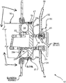
- FIG. 2 is a detailed depiction of the glove leak test module, in accordance with features of the present invention.
- FIG. 3 is a graph of testing system results, in accordance with features of the present invention.
- references to “one embodiment” of the present invention are not intended to be interpreted as excluding the existence of additional embodiments that also incorporate the recited features.
- embodiments “comprising” or “having” an element or a plurality of elements having a particular property may include additional such elements not having that property.
- the invention provides a Gloveport Glove Testing System (GGTS) that provides quick, affordable, and reliable In-Situ testing of containment in glovebox gloves for microscopic leaks.
- GGTS Gloveport Glove Testing System
- the invention is primarily designed to be used for negative pressure gloveboxes. (Negative pressure means that the atmosphere within the glove box is at a lower pressure than ambient pressure.)
- the GGTS uses a pressure decay process to determine glove failure and leakage. Holes as small as 1/64 th of an inch (397 microns) in diameter can be detected with the invented method and device. Typical tests are 3 minutes in length, but can be longer or shorter, depending on the size of the breach.
- a glove tester module (discussed below) is the main component of the GGTS.
- the sealing mechanism is sized to fit with gloves inserted into an eight-inch diameter glove port, such as a Zollinger Glove Ring. It can be adapted for other glove port sizes. It provides a leak free seal between the glove interior and the room atmosphere. Benefits of the invention include its lightweight and portability, ease of operation and maintenance, and no requirement for external electric power or unique parts.
- the module is fitted with a calibrated analog pressure gauge which allows for measuring leak rates.
- FIG. 1 is a schematic diagram of a system for testing glovebox gloves in situ, that system designated as numeral 10 .
- a salient feature of the invention is the above stated glove tester module 12 which comprises a reversibly inflatable collar 14 .
- the collar 14 in a deflated mode, allows the tester to be inserted into the aperture 15 ( FIG. 2 ) of a glove such that the interior periphery of the cuff of the glove resides between the collar and the glovebox aperture 15 .
- Standard glovebox diameters for gloves is eight inches, but the invented system is not relegated to that diameter.
- a secondary seal 17 is provided by a gasket material butted up against the face of the gloveport 15 .
- the collar which may comprise an inner-tube, is charged with a pressurized fluid (e.g., air, nitrogen, CO 2 , etc.) via a first fluid ingress conduit 18 having a first end 20 originating at a three way valve 34 .
- a second end 24 terminates at a manifold 26 proximal to the collar via a first two way valve 23 positioned intermediate the second end 24 and the manifold 26 .
- a first port of the three way valve 34 accepts fluid from a fluid reservoir 22 to initially charge the system.
- a tank fill port and valve 21 may be situated upstream of the fluid reservoir.
- the fluid reservoir 22 may include a tank drain valve 25 .
- the first two way valve 23 intermediate the second end of the first conduit 18 and the manifold 26 , is provided as a hermetic seal between the main pressure loop 18 and the collar 14 .
- the glove 16 undergoing testing is charged with a second conduit 28 .
- the second conduit 28 is provided as a second means of fluid ingress from the pressurized fluid supply 22 to the manifold 26 .
- a first end 30 of the second conduit originates at the three way valve 34 while a second end 32 of the second conduit is attached to a second two way valve 25 mounted to and in fluid communication with the manifold 26 .
- Pressure drop during the test is monitored via a pressure gauge 56 positioned at the second end of the second fluid conduit and intermediate the second two way valve 25 of that conduit and the manifold 26 . (That pressure gauge may have a range of between 0 and 30 inches WC.)
- the GGTS includes a multi-gallon air receiver tank 22 and a pneumatic control panel 11 .
- a gas source 22 is used for the module 12 to perform the pressure decay leak test.
- a myriad of gasses are suitable, including air, nitrogen, argon, CO 2 and combinations thereof. Generally, any noncorrosive gas can be utilized.
- the receiver tank may be filled with dedicated building compressed air or filled from compressed gas cylinders. In an application of the invented system and method, the receiver tank is filled and pressurized to approximately 90 psig. This will allow enough capacity for testing approximately 20 glovebox gloves.
- a control panel 11 regulates fluid flow to and from the testing module 12 .
- the control panel 11 comprises and physically support the first fluid conduit 18 and the second fluid conduit 28 .
- pressure regulators, pressure relief devices and values provide compressed gas to the inflatable rubber tube 14 for the primary seal, and to inflate the glove for pressure decay testing.
- the control panel 11 operates under two modes: the sealing mode and the testing mode.
- the sealing mode regulates the 90 psi tank pressure to about 22 psig operating pressure in the first fluid conduit 18 to provide a reliable primary seal between the interior surface of the glove cuff and the testing module 12 .
- a three way valve 34 is actuated to switch operations from the sealing mode to the glove inflation and testing mode.
- the glove testing mode regulates the 90 psig tank pressure to a lower operating pressure relative to the pressure necessary to establish the primary seal.
- the primary seal pressure for sufficiently inflating the inner tube 14 ranges from about 20 psig to about 25 psig, while suitable glove inflation pressures are approximately 0.3 psig (approximately 8 inches water column).
- FIG. 2 is a detailed view of the modular leak tester 12 . This figure is provided to provide fluid conduit detail through the manifold 26 of the tester 12 .
- a second end 24 of a first fluid conduit 18 terminates in a valve 23 .
- This valve 23 may be a two way valve so as to selectively charge the circumferentially expanding seal 14 .
- the second end 32 of the second fluid conduit 28 terminates in a second two way valve 25 .
- the two way valve is in fluid communication with the interior void defined by the glove 16 .
- Flow to the inner tube 14 is routed from the gas supply into the manifold and then from the manifold through tubing/tube fittings to the inner tube.
- Flow to the glove is routed from the gas supply 22 , stepped down in pressure, and then through the manifold 26 and into the glove interior.
- FIG. 2 also depicts the gasket 17 for forming the secondary seal 17 compressed against a laterally protruding lip 19 of the glove port aperture 15 , that laterally protruding lip comprising an exterior surface of the glovebox 13 .
- This secondary gasket is removably secured to exterior surfaces 19 of the glovebox 13 defining the port aperture 15 .
- the hermetic action of the secondary seal is established simultaneously with when the first seal is established. This is because both the inner tube 14 and the gasket 17 forming the secondary seal are both supported by the manifold 26 .
- the shape of the manifold maybe similar to the shape formed by the glovebox port, so as to be circular in most instances.
- the reversibly inflatable tube 14 is received by a periphery 27 of the manifold 26 .
- the periphery 27 defines a circumferentially extending annular channel defined by a pair of radially extending surfaces 29 i (“i” for that surface residing within the glovebox 13 when the manifold 26 nests fully within the gloveport), and 290 (“o” for that surface residing outside of the glovebox 13 when the manifold nests fully within the gloveport).
- the outside radially extending flange or surface 290 defines an outer diameter of the manifold 26 that is relatively larger than the diameter of the gloveport, thereby defining an overhang. This overhang prevents over insertion of the manifold into the gloveport.
- the medially facing surface of this overhang provides support for the gasket 17 so that the gasket 17 is positioned between the medially facing surface of the second radially extending surface 290 and the exterior of the glovebox.
- the overhang backstops the entire width of the gasket 17 .
- a perpendicularly disposed surface 31 Positioned at the proximal ends of the surfaces 29 i and 290 is a perpendicularly disposed surface 31 so as to form a floor of the channel.
- FIG. 2 shows the tube slightly deformed as a result of this compression effect.
- the sealing substrate for the tube 14 A myriad of materials are commercially available as the sealing substrate for the tube 14 .
- inner tube Model Number 20991 2.80/2.50-4 inner tube from Marathon, a division of Global Industries, or Item Number 4991T29 angled inner tube from McMaster-Carr is suitable.
- the tube when inflated has an outside diameter of approximately 8 inches.
- Other tube sizes would be used for concomitantly different glove port aperture diameters.
- the secondary seal 17 gasket material may comprise reversibly deformable material selected from the group consisting of silicone foam (closed cell), neoprene foam (closed cell), rubber, and combinations thereof.
- a salient feature of the system is that the modular leak tester 12 can operate at a location remote from its control panel 11 or pressurized fluid supply 22 .
- the module can be placed within the glove port with a single human hand, and without mechanical assistance (cable pullers, winches, etc.).
- Another feature is that the modular leak tester mounts inside of the glove port rings.
- the system is simple in design in that no electronics are involved. Rather, the system is run entirely pneumatically. These features free up or otherwise allows other surfaces or glove ports to remain unencumbered and uncluttered during testing of a particular glove or pair of gloves.
- the module 12 of the GGTS is designed to test one glove at a time. If the glove is determined to have a leak, then only that glove is replaced. However, additional piping and valves can be incorporated within the control panel to accommodate a second module 12 to work simultaneously with the first module.
- FIG. 3 is a graph showing results of the leak testing with the invented system and method. As can be discerned from the graph, punctures of 1/64 th of an inch were detected almost immediately. Whereas nonpunctured leak rates (i.e., pressure drop) over a period of 3 minutes varied between 0.1 and 1.5 inches water column, leak rates (i.e., pressure drop) of 1/64′′ punctures varied between 3 and 3.4 inches water column over the 3 minute test period.
- FIG. 3 also depicts leak rates (i.e., pressure drop) of 1/32′′ punctures of 4 inches of water in ⁇ 1.5 minutes of the 3 minute test period.
- the present invention encompasses not only the entire group listed as a whole, but each member of the group individually and all possible subgroups of the main group. Accordingly, for all purposes, the present invention encompasses not only the main group, but also the main group absent one or more of the group members. The present invention also envisages the explicit exclusion of one or more of any of the group members in the claimed invention.
Landscapes
- Engineering & Computer Science (AREA)
- Physics & Mathematics (AREA)
- General Physics & Mathematics (AREA)
- Robotics (AREA)
- Mechanical Engineering (AREA)
- Examining Or Testing Airtightness (AREA)
Abstract
Description
-
- Locate the compressed air or inert gas source specified by the user. Also obtain the user's dual-stage pressure regulator and pneumatic hose rated at minimum 300 psi. At the discretion of the respective facility, a building air hookup that provides no greater than 100 psig may be used.
- Verify that the user's pressure regulator is closed. Verify that the
GGTS tank 22 fill valve and thetank block valve 38 are closed. Also verify that the three-waydirectional valve 34 is set to block. Upstream from theblock valve 38 may be positioned a pressure relievevalve 39. Thatrelief valve 39 may be set at 125 psig. In fluid communication with that relief valve may be apressure gauge 35 having a range of between 0 and 160 psig. - Attach the user's pressure regulator 42 to the gas cylinder (or the building air hookup) and connect a pneumatic hose from the regulator to the tank fill port.
- Use the pneumatic hose to connect the pressure regulator and GGTS tank fill valve. Slowly open the GGTS tank fill valve. Slowly open the gas or air source valve. Slowly open the pressure regulator valve to begin filling the
GGTS tank 22. Fill it to a maximum pressure of 90 psig. - Once the GGTS tank is filled, close the gas or air source valve. Close the GGTS tank fill valve. Close the pressure regulator. Slowly unscrew the pneumatic hose from the GGTS tank fill valve and bleed the remaining air out of it. Once the pressure regulator output pressure gauge reads 0 psig, unscrew or “quick-disconnect” the pneumatic line from the tank fill valve and user's pressure regulator.
- In order to tune the GGTS regulators, close all valves and pressure regulators. Remove GLOVE side pressure regulators 46 and 42 g and use an appropriate socket wrench (e.g., 9/32-in) to perform adjustments. (Pressure regulators operate as follows: clockwise to open and counterclockwise to close.) An exemplary first glove side pressure regulator may have an operating range of from 0 to 10 psig, with a maximum inlet pressure of 100 psig. The second glove side pressure regulator 42 g, situated downstream from the first regulator 46, may have an operating range of between 0 and 2 psig, with a maximum inlet pressure of 15 psig.
- Set metering valves to full open. Slowly open the tank block valve, allow pressure to flow up to the three
way valve 34, and verify that thepressure gauge 41 positioned upstream of thethreeway valve 34 is within ±3 psi of the tank pressure gauge. This pressure gauge may have a range of between 0 and 160 psig. - To tune
inner tube 14 inflation, slowly set the threeway valve 34 to the firstfluid conduit 18 and allow pressure to flow to the pressure regulator 42 t. An exemplary tube side pressure regulator 42 may have an operating range of from 0 to 25 psig and a maximum inlet pressure of 100 psig. Close an upstream valve 43 positioned between the regulator 42 t and thedownstream valve 44, wherein thedownstream valve 44 is proximal to avent port 45 dedicated to thefirst conduit 18. Ametering valve 49 may be positioned between the upstream valve 43 and the pressure regulator 42 t. Downstream from the tube side pressure regulator 42 is apressure gauge 52. An exemplary operating range of thegauge 52 is between 0 and 30 psig. Downstream of thatpressure gauge 52 may be situated a pressure relief valve 53. This pressure relief valve 53 may be set at 32 psig. - Slowly adjust the pressure regulator 42 t to an output of approximately 22.5±1 psig. Adjust the metering valve to obtain the desired glove fill rate and vent through the
valve 44 as necessary. - Slowly set the three
way valve 34 to establish fluid communication between it and the secondfluid conduit 28, so as to allow pressure to flow to theglove line 28 pressure regulator 46, whereby the pressure regulator is positioned upstream of aglove line vent 47 port and downstream of the threeway valve 34. Slowly adjust the first glove line pressure regulator 46 to an output of about 10 psig, as indicated by the pressure reading on the gloveline pressure gauge 48 positioned immediately downstream. A first two way valve in thefirst conduit 18 is opened, that valve positioned downstream of the pressure gauge 54. - Slowly adjust the pressure regulator 42 g to output the glove testing pressure of 8 inches water column (hereinafter “in. WC”) but no greater than three turns open (clock-wise). This corresponds to a 30- to 60-second glove fill time. The pressure regulator 42 g has an operating range up to 2 psig (55.4 in. WC) and ideally is to be set at its lower operating range of the glove testing pressure of 0.29 psig (8 in. WC).
- Prior to using the GGTS to test a glove, inspect the glove to be tested for any obvious signs of leaks/deterioration. As needed, pause work for glove inspection or gauge recalibration.
- Before initiating testing, view the GGTS tank pressure gauge and If the gauge reads greater than 90 psig, slowly open the tank drain valve to vent excess pressure. Close all valves on the
control panel 11 and theglove tester module 12. - Open the GGTS tank block valve and verify that the
tank pressure gauge 41 reads less than or equal to 90 psig and is within ±3 psi of the tank pressure gauge. Insert theglove tester module 12 into theglove 16 to be tested. Set the threeway valve 34 to charge the firstfluid conduit 18. Open the upstream valve 43 and wait for its respective pressure gauge 52 (which is situated directly downstream of the upstream valve 43) to stabilize at a reading of 20-25 psig. Insert theglove tester module 12 into thegloveport 15 until theradially extending flange 290 abuts the exterior periphery of the gloveport. This will assure aproper gasket 17 and seal 14 positioning before inflating the tube. - Open the upstream valve 43 to inflate the tube and wait until the
pressure gauge 52 reading stabilizes at 20-25 psig. Close that upstream valve 43. - Set the three
way valve 34 to charge the second fluid conduit 28 (i.e., the glove charge line). View the first gloveline pressure gauge 48 and verify that it reads less than 15 psig. - Open the first two-
way valve 50 on the secondfluid conduit 28 and wait until its downstream pressure gauge 54 stabilizes. This pressure gauge 54 may have an operating range of between 0 and 5 psig. Downstream of this pressure gauge 54 is apressure relief valve 55 which may be set at a release pressure of 1 psig. Then, open the second twoway valve 25 proximal to the manifold 26 and wait approximately 1-2 minutes, until theglove 16 fills with gas, while watching itsrespective pressure gauge 56 which is in fluid communication with both the twoway valve 50 and the interior void of theglove 16. While the glove is filling with gas, thepressure gauge 56 will slowly rise in pressure. Once glove is filled, pressure will start to rise rapidly. If glove pressure inadvertently goes over 10 in. WC, the operator may terminate the test as there is the potential for false positive results. The operator may wait until glove pressure reaches 9 in. WC for 30-mil gloves or 6 in. WC for 15-mil gloves. - When the pressure gauge 59 reads 9 inches WC, close the second two-
way valve 25 and then the first twoway valve 50 on the secondfluid conduit 28. When the glove pressure drops to 1 in. WC (+/−0.2 in. WC), start the timer (8 in. WC for 30-mil gloves or 5 in. WC for 15-mil gloves). Wait 3 minutes for pressure to decay and record thepressure gauge 56 reading. If glove pressure drops below 6 in. WC for 30-mil glove or drops below 3 in. WC for 15-mil glove (+/−0.2 in. WC), the glove has failed, with a minimum detectable puncture of 0.0313 in. (794 μm). The 3-minute required test time for pressure to decay and 8/6 in. WC or 5/3 in. WC (+/−0.2 in. WC) starting test pressure/pass-fail pressure can be adjusted at the discretion of the radiological safety officer.
Claims (14)
Priority Applications (1)
| Application Number | Priority Date | Filing Date | Title |
|---|---|---|---|
| US15/712,877 US10690565B2 (en) | 2017-09-22 | 2017-09-22 | In-situ gloveport glove leak tester |
Applications Claiming Priority (1)
| Application Number | Priority Date | Filing Date | Title |
|---|---|---|---|
| US15/712,877 US10690565B2 (en) | 2017-09-22 | 2017-09-22 | In-situ gloveport glove leak tester |
Publications (2)
| Publication Number | Publication Date |
|---|---|
| US20190094102A1 US20190094102A1 (en) | 2019-03-28 |
| US10690565B2 true US10690565B2 (en) | 2020-06-23 |
Family
ID=65806628
Family Applications (1)
| Application Number | Title | Priority Date | Filing Date |
|---|---|---|---|
| US15/712,877 Active 2037-12-05 US10690565B2 (en) | 2017-09-22 | 2017-09-22 | In-situ gloveport glove leak tester |
Country Status (1)
| Country | Link |
|---|---|
| US (1) | US10690565B2 (en) |
Families Citing this family (7)
| Publication number | Priority date | Publication date | Assignee | Title |
|---|---|---|---|---|
| FR3102556B1 (en) * | 2019-10-25 | 2021-11-19 | Getinge La Calhene | SYSTEM LEAK TEST DEVICE FOR SEALING TWO MEDIA |
| CN111844139A (en) * | 2020-07-30 | 2020-10-30 | 南京都德智能科技有限公司 | Glove box |
| CN112362263B (en) * | 2020-12-02 | 2022-08-09 | 青海省药品检验检测院 | Medical glove tightness leak detector |
| DE202021106449U1 (en) | 2021-11-26 | 2021-12-06 | Mustafa Basthikodi | Smart gloves for measuring pressure and monitoring skin health |
| CN116818198A (en) * | 2023-06-25 | 2023-09-29 | 湖北米开罗那机电技术有限公司 | Glove box glove detection device |
| CN117664707B (en) * | 2024-01-31 | 2024-04-23 | 山东海奥斯生物科技股份有限公司 | Intelligent pressure-resistant collagen membrane detection equipment |
| CN119714720B (en) * | 2024-11-15 | 2025-10-17 | 中国辐射防护研究院 | Device and method for detecting glove leakage rate of glove box by utilizing vacuum deoxygenation |
Citations (7)
| Publication number | Priority date | Publication date | Assignee | Title |
|---|---|---|---|---|
| US1773546A (en) * | 1929-05-10 | 1930-08-19 | Harry J Rider | Electric immersion heater |
| US4206631A (en) | 1978-06-02 | 1980-06-10 | Batavian Rubber Company Limited | Inflatable product testing |
| FR2530813A1 (en) * | 1982-07-20 | 1984-01-27 | Commissariat Energie Atomique | Leak-detection device for a glove of a box with gloves comprising means for pressurising the glove. |
| US6810715B2 (en) * | 2003-02-03 | 2004-11-02 | The Regents Of The University Of California | In-situ leak testing of glovebox, isolator, or containment unit gloves |
| US7174772B2 (en) | 2005-02-12 | 2007-02-13 | Giuseppe Sacca | System and method for leak detection |
| US20110000282A1 (en) * | 2009-07-01 | 2011-01-06 | Los Alamos National Security, Llc | Passive glovebox glove leak detector |
| US20110259933A1 (en) * | 2010-04-24 | 2011-10-27 | GM Global Technology Operations LLC | Tank module for a motor vehicle |
-
2017
- 2017-09-22 US US15/712,877 patent/US10690565B2/en active Active
Patent Citations (7)
| Publication number | Priority date | Publication date | Assignee | Title |
|---|---|---|---|---|
| US1773546A (en) * | 1929-05-10 | 1930-08-19 | Harry J Rider | Electric immersion heater |
| US4206631A (en) | 1978-06-02 | 1980-06-10 | Batavian Rubber Company Limited | Inflatable product testing |
| FR2530813A1 (en) * | 1982-07-20 | 1984-01-27 | Commissariat Energie Atomique | Leak-detection device for a glove of a box with gloves comprising means for pressurising the glove. |
| US6810715B2 (en) * | 2003-02-03 | 2004-11-02 | The Regents Of The University Of California | In-situ leak testing of glovebox, isolator, or containment unit gloves |
| US7174772B2 (en) | 2005-02-12 | 2007-02-13 | Giuseppe Sacca | System and method for leak detection |
| US20110000282A1 (en) * | 2009-07-01 | 2011-01-06 | Los Alamos National Security, Llc | Passive glovebox glove leak detector |
| US20110259933A1 (en) * | 2010-04-24 | 2011-10-27 | GM Global Technology Operations LLC | Tank module for a motor vehicle |
Non-Patent Citations (1)
| Title |
|---|
| English Translation FR 2530813, Legendre, Leak-detection device for a glove of a box with gloves comprising means for pressurizing the glove, Jan. 1984 (Year: 1984). * |
Also Published As
| Publication number | Publication date |
|---|---|
| US20190094102A1 (en) | 2019-03-28 |
Similar Documents
| Publication | Publication Date | Title |
|---|---|---|
| US10690565B2 (en) | In-situ gloveport glove leak tester | |
| US7240697B2 (en) | Apparatus and method for isolating and testing a segment of pipelines | |
| US8261596B2 (en) | Seal assembly with leak monitoring | |
| US7827853B2 (en) | Weld testing apparatus and method for nozzles | |
| US6234007B1 (en) | Leak testing device | |
| US8015859B2 (en) | Nozzle testing apparatus and method | |
| RU2678779C1 (en) | Improved methods and device for testing liner tube tightness | |
| KR101495784B1 (en) | Device for collecting and leak detecting of gas pipeline | |
| CN206074195U (en) | A kind of low temperature seal experiment test device | |
| CN109506845B (en) | Testing device and testing method for pipeline weld joint leakage detection | |
| US20130161850A1 (en) | Autoclave health monitoring and control system | |
| KR20250005270A (en) | Joint Leakage Detection System | |
| CN109781716A (en) | Gas indicator | |
| CN105003713A (en) | Sealing end cover of ball valve | |
| US5665903A (en) | Technique for testing pipe couplings for defects | |
| CN207675387U (en) | single-station sealing test system | |
| JP5347633B2 (en) | Grommet still water inspection equipment | |
| CN108801771A (en) | A kind of high pressure charge and discharge rubber lined hose strength test device | |
| JP2020076544A (en) | Leakage inspection method of condenser | |
| JP2008501892A (en) | Apparatus and method for collecting and confining leaked sulfur hexafluoride gas | |
| CN104776962B (en) | Valve detection fixture and the valve detecting system with the fixture | |
| CN108663177A (en) | A kind of connector box method for conducting leak test and device | |
| CN208596077U (en) | A kind of high pressure charge and discharge rubber lined hose strength test device | |
| CN114235304A (en) | System and method for searching leakage of mechanical penetration piece of containment vessel of nuclear power station | |
| JP5667037B2 (en) | Pipeline leak tester |
Legal Events
| Date | Code | Title | Description |
|---|---|---|---|
| FEPP | Fee payment procedure |
Free format text: ENTITY STATUS SET TO UNDISCOUNTED (ORIGINAL EVENT CODE: BIG.); ENTITY STATUS OF PATENT OWNER: SMALL ENTITY |
|
| FEPP | Fee payment procedure |
Free format text: ENTITY STATUS SET TO SMALL (ORIGINAL EVENT CODE: SMAL); ENTITY STATUS OF PATENT OWNER: SMALL ENTITY |
|
| AS | Assignment |
Owner name: UCHICAGO ARGONNE, LLC, ILLINOIS Free format text: ASSIGNMENT OF ASSIGNORS INTEREST;ASSIGNORS:HASKE, KYLE;SMITH, JAMES;SAKOWSKI, MARK;AND OTHERS;REEL/FRAME:044280/0441 Effective date: 20171023 |
|
| STPP | Information on status: patent application and granting procedure in general |
Free format text: NON FINAL ACTION MAILED |
|
| STPP | Information on status: patent application and granting procedure in general |
Free format text: RESPONSE TO NON-FINAL OFFICE ACTION ENTERED AND FORWARDED TO EXAMINER |
|
| STPP | Information on status: patent application and granting procedure in general |
Free format text: NOTICE OF ALLOWANCE MAILED -- APPLICATION RECEIVED IN OFFICE OF PUBLICATIONS |
|
| STPP | Information on status: patent application and granting procedure in general |
Free format text: PUBLICATIONS -- ISSUE FEE PAYMENT RECEIVED |
|
| STCF | Information on status: patent grant |
Free format text: PATENTED CASE |
|
| MAFP | Maintenance fee payment |
Free format text: PAYMENT OF MAINTENANCE FEE, 4TH YR, SMALL ENTITY (ORIGINAL EVENT CODE: M2551); ENTITY STATUS OF PATENT OWNER: SMALL ENTITY Year of fee payment: 4 |