US10690499B2 - Analysis system, analysis method, and storage medium in which analysis program is stored - Google Patents
Analysis system, analysis method, and storage medium in which analysis program is stored Download PDFInfo
- Publication number
- US10690499B2 US10690499B2 US16/139,646 US201816139646A US10690499B2 US 10690499 B2 US10690499 B2 US 10690499B2 US 201816139646 A US201816139646 A US 201816139646A US 10690499 B2 US10690499 B2 US 10690499B2
- Authority
- US
- United States
- Prior art keywords
- inclination
- point cloud
- cloud data
- dimensional point
- analysis
- Prior art date
- Legal status (The legal status is an assumption and is not a legal conclusion. Google has not performed a legal analysis and makes no representation as to the accuracy of the status listed.)
- Active
Links
Images


Classifications
-
- G—PHYSICS
- G01—MEASURING; TESTING
- G01C—MEASURING DISTANCES, LEVELS OR BEARINGS; SURVEYING; NAVIGATION; GYROSCOPIC INSTRUMENTS; PHOTOGRAMMETRY OR VIDEOGRAMMETRY
- G01C15/00—Surveying instruments or accessories not provided for in groups G01C1/00 - G01C13/00
- G01C15/10—Plumb lines
-
- G—PHYSICS
- G01—MEASURING; TESTING
- G01C—MEASURING DISTANCES, LEVELS OR BEARINGS; SURVEYING; NAVIGATION; GYROSCOPIC INSTRUMENTS; PHOTOGRAMMETRY OR VIDEOGRAMMETRY
- G01C15/00—Surveying instruments or accessories not provided for in groups G01C1/00 - G01C13/00
- G01C15/10—Plumb lines
- G01C15/105—Optical plumbing
-
- G—PHYSICS
- G06—COMPUTING OR CALCULATING; COUNTING
- G06T—IMAGE DATA PROCESSING OR GENERATION, IN GENERAL
- G06T15/00—Three-dimensional [3D] image rendering
- G06T15/005—General purpose rendering architectures
-
- A—HUMAN NECESSITIES
- A61—MEDICAL OR VETERINARY SCIENCE; HYGIENE
- A61B—DIAGNOSIS; SURGERY; IDENTIFICATION
- A61B5/00—Measuring for diagnostic purposes; Identification of persons
- A61B5/103—Measuring devices for testing the shape, pattern, colour, size or movement of the body or parts thereof, for diagnostic purposes
- A61B5/107—Measuring physical dimensions, e.g. size of the entire body or parts thereof
-
- G—PHYSICS
- G06—COMPUTING OR CALCULATING; COUNTING
- G06T—IMAGE DATA PROCESSING OR GENERATION, IN GENERAL
- G06T2207/00—Indexing scheme for image analysis or image enhancement
- G06T2207/10—Image acquisition modality
- G06T2207/10028—Range image; Depth image; 3D point clouds
Definitions
- the present disclosure relates to an analysis system, an analysis method, and a storage medium in which an analysis program is stored for analyzing inclination of an object to be measured in plumbing the object at a construction site, the object being a long structural member such as a column.
- some methods for measuring verticality (plumb) of column members are known. Examples of the methods include a method using a plumb bob and a method using a measuring instrument such as a transit that can determine the verticality of the column members by measuring them in two directions.
- a method using linearity of a laser beam for detecting inclination of the column members is known. Specifically, a laser plummet instrument that emits a laser beam vertically downward to the ground is mounted on the upper end of a column member and a point for receiving the laser beam is set at a certain position on the ground. The point is set at such a position that is hit by the laser beam if the column member is erected vertically. Adjusting the inclination of the column member such that the laser dot coincides with the point can plumb the column member (see Japanese Unexamined Patent Publication No. 2001-304865, for example).
- plumb bob When a plumb bob is used in plumbing, the plumb bob swings in high wind, which requires time before the plumb bob stops. When a measuring instrument such as a transit is used, workers need to measure the column member in at least two directions, which requires many work processes and time.
- Embodiments of the present disclosure have been made to solve the problems above, and the present disclosure intends to provide an analysis system, an analysis method, and a storage medium in which an analysis program is stored that can achieve stable and efficient plumbing.
- the analysis system is designed to analyze inclination of an object to be measured, the analysis system including a data acquisition unit configured to acquire three-dimensional point cloud data of the object, a surface detector configured to detect a surface of the object based on the three-dimensional point cloud data, and an inclination analyzer configured to analyze inclination of the object by calculating inclination of the surface detected by the surface detector.
- the analysis method is designed to analyze inclination of an object to be measured, the analysis method including acquiring three-dimensional point cloud data of the object, detecting a surface of the object based on the three-dimensional point cloud data, and analyzing inclination of the object by calculating inclination of the surface detected at the detecting.
- the storage medium in which an analysis program is stored is a non-transitory storage medium designed to store therein an analysis program for analyzing inclination of an object to be measured, the analysis program causing a computer to execute acquiring three-dimensional point cloud data of the object, detecting a surface of the object based on the three-dimensional point cloud data, and analyzing inclination of the object by calculating inclination of the surface detected at the detecting.
- Embodiments of the present disclosure having such configurations above can achieve stable and efficient plumbing.
- FIG. 1 is a schematic overview of an analysis system according to an embodiment of the present disclosure
- FIG. 2 is a block diagram illustrating a control system of devices included in the analysis system
- FIG. 3 is a flowchart illustrating a routine for analyzing inclination of column members
- FIG. 4A illustrates a display example of a display unit in setting measurement conditions
- FIG. 4B illustrates a display example of an inclination analysis result
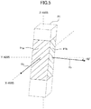
- FIG. 5 is a diagram illustrating inclination of a column member
- FIG. 6 is a schematic overview of an analysis system according to a modification of the present disclosure.
- FIG. 7 illustrates a display example of a display unit according to the modification of the present disclosure.
- FIG. 1 is a schematic overview of an analysis system according to the embodiment of the present disclosure
- FIG. 2 is a block diagram illustrating a control system of devices included in the analysis system that are a laser scanner, a server, and an information terminal. The configuration of the analysis system according to the present embodiment will be described with reference to FIGS. 1 and 2 .
- FIG. 1 an example inclination analysis for four rectangular columns that have been erected in position is described.
- the four columns, first to fourth column members P 1 , P 2 , P 3 , and P 4 are example objects to be measured.
- the inclination analysis is performed in plumbing the column members.
- This analysis system 1 includes a laser scanner 10 (measuring device) that can generate three-dimensional point cloud data by scanning a measurement light beam and receiving the reflected light beam, a server 20 that functions as an analysis device configured to acquire the three-dimensional point cloud data from the laser scanner 10 and analyze the inclination of the column members P 1 , P 2 , P 3 , and P 4 , and an information terminal 30 that can display the three-dimensional point cloud data including the column members P 1 , P 2 , P 3 , and P 4 and a result of the inclination analysis and can set analysis conditions.
- a laser scanner 10 (measuring device) that can generate three-dimensional point cloud data by scanning a measurement light beam and receiving the reflected light beam
- a server 20 that functions as an analysis device configured to acquire the three-dimensional point cloud data from the laser scanner 10 and analyze the inclination of the column members P 1 , P 2 , P 3 , and P 4
- an information terminal 30 that can display the three-dimensional point cloud data including the column members P 1
- the analysis system 1 is what is called a cloud computing system that communicably connects the laser scanner 10 with the server 20 , and the server 20 with the information terminal 30 via a communication network such as the Internet.
- a communication network such as the Internet.
- data generated by the laser scanner 10 is transmitted to the server 20 and an analysis result from the server 20 is displayed on the information terminal 30 .
- the information terminal 30 can be used to control the laser scanner 10 via the server 20 .
- the laser scanner 10 includes a scanning unit 11 , a data generation unit 12 , a communication unit 13 , and a storage unit 14 that are electrically connected with each other.
- the laser scanner 10 may include a display unit and an operating unit and may be connected to various types of sensors, which are not illustrated in FIG. 2 .
- the blocks illustrated in FIG. 2 indicate processing functions executed by a computer or parts of the devices in accordance with a computer program. These functions are mainly implemented by an arithmetic processing device such as a central processing unit (CPU).
- CPU central processing unit
- the scanning unit 11 includes a distance-measuring unit 11 a and a horizontal rotation unit 11 b .
- the distance-measuring unit 11 a has a vertically rotatable structure and emits and receives a laser beam (measurement light beam).
- the horizontal rotation unit 11 b supports the distance-measuring unit 11 a and has a horizontally rotatable structure.
- the horizontal rotation unit 11 b rotates the distance-measuring unit 11 a in a horizontal direction and the distance-measuring unit 11 a swings vertically upward and downward in a certain range and emits and receives a laser beam, or measures a distance.
- the laser scanner 10 performs scanning operation in this manner.
- the distance-measuring unit 11 a and the horizontal rotation unit 11 b are each provided with an angle meter, which is not illustrated. Upon measurement of a distance, the distance and a horizontal angle at which the horizontal rotation unit 11 b rotates and a vertical angle at which the distance-measuring unit 11 a swings are stored in the storage unit 14 . As described above, the scanning unit 11 can scan the measurement light beam horizontally all around the laser scanner 10 and in a certain range in the height direction.
- the data generation unit 12 generates three-dimensional point cloud data from the distance, the horizontal angle, and the vertical angle of each focus point acquired in the scanning operation of the scanning unit 11 .
- a three-dimensional model of structures around the laser scanner 10 such as the column members P 1 , P 2 , P 3 , and P 4 , can be created from the three-dimensional point cloud data.
- the three-dimensional model can visualize the size and shape of the structures.
- the communication unit 13 is a wireless communication unit such as a wireless local area network (LAN).
- the communication unit 13 is configured to connect to a communication network such as the Internet and transmit and receive information.
- the communication unit 13 may include a wired communication unit that communicates via a connection terminal (communication units to be described later may also include wired communication units).
- the storage unit 14 is, for example, a flash memory or a magnetic disk memory, and is configured to store therein information such as the three-dimensional point cloud data generated by the data generation unit 12 .
- the server 20 includes a data acquisition unit 21 , a surface detector 22 , an inclination analyzer 23 , a communication unit 24 , and a measurement controller 25 that are electrically connected with each other.
- the server 20 includes other units such as a storage unit, which are not illustrated, and at least three-dimensional point cloud data and other information can be stored in the storage unit.
- the storage unit stores therein an analysis program for causing a computer of the server 20 to execute an analysis method, which will be described later.
- the data acquisition unit 21 is configured to acquire the three-dimensional point cloud data generated by the laser scanner 10 via the communication unit 24 .
- the surface detector 22 is configured to detect surfaces of the column members P 1 , P 2 , P 3 , and P 4 from the three-dimensional point cloud data acquired by the data acquisition unit 21 . Surfaces are detected by, for example, what is called plane fitting. In plane fitting, a plane model is fitted to a three-dimensional model created based on three-dimensional point cloud data. As illustrated in FIG.
- the laser scanner 10 in the present embodiment is substantially equally spaced apart from the four column members P 1 , P 2 , P 3 , and P 4 , the laser scanner 10 detects only two surfaces of each of the column members P 1 , P 2 , P 3 , and P 4 close to the laser scanner 10 , namely surfaces P 1 a , P 1 b , P 2 a , P 2 b , P 3 a , P 3 b , P 4 a , and P 4 b , which may be hereinafter referred to as the surfaces P 1 a to P 4 b.
- the inclination analyzer 23 is configured to calculate inclination of the surfaces of the column members P 1 , P 2 , P 3 , and P 4 detected by the surface detector 22 to calculate inclination of the column members P 1 , P 2 , P 3 , and P 4 .
- the inclination analyzer 23 calculates inclination of two surfaces of each of the column members P 1 , P 2 , P 3 , and P 4 indicated by shaded areas in FIG. 1 , and the inclination of the entire column members can be represented by calculating the inclination of the surfaces.
- the inclination analyzer 23 transmits inclination information of the column members after analysis to a corresponding information terminal 30 via the communication unit 24 .
- the communication unit 24 is configured to transmit and receive information by connecting to a communication network such as the Internet in the same manner as the communication unit 13 of the laser scanner 10 .
- the measurement controller 25 is configured to remotely control the laser scanner 10 via the communication unit 24 .
- the measurement controller 25 can control the measurement range of the scanning unit 11 of the laser scanner 10 .
- the measurement controller 25 acquires positional information including installation positions of the column members P 1 , P 2 , P 3 , and P 4 , such as CAD data or other design data, and limits the measurement range of the laser scanner 10 to a certain range including the column members P 1 , P 2 , P 3 , and P 4 based on the positional information.
- Such design data may be acquired (uploaded) from an external device such as the laser scanner 10 or the information terminal 30 , or may be stored in the storage unit of the server 20 in advance.
- the information terminal 30 includes a display unit 31 , an operating unit 32 , and a communication unit 33 that are electrically connected with each other.
- the information terminal 30 may be, for example, a dedicated terminal designed for use with the laser scanner 10 , or may be a general-purpose device such as a smartphone or a tablet-type personal computer (PC) installed with an application program for the analysis system.
- the information terminal 30 in particular is a portable terminal so that the workers can perform plumbing while checking on the display unit 31 .
- the display unit 31 is a display configured to acquire inclination information of the column members P 1 , P 2 , P 3 , and P 4 calculated by the inclination analyzer 23 of the server 20 and display the information.
- the operating unit 32 is configured to receive operations on the information terminal 30 and receive various types of operating instructions and settings to the laser scanner 10 .
- the operating unit 32 is configured by, for example, a touch screen integrated with the display unit 31 or configured by one or more buttons.
- the communication unit 33 is configured to transmit and receive information by connecting to a communication network such as the Internet in the same manner as the communication unit 13 of the laser scanner 10 .
- the analysis system 1 having the configuration above is used after the column members P 1 , P 2 , P 3 , and P 4 are erected in position.
- the laser scanner 10 is set, for example, at a position substantially equally spaced apart from the column members P 1 , P 2 , P 3 , and P 4 to perform scanning operation and the server 20 acquires three-dimensional point cloud data of the column members P 1 , P 2 , P 3 , and P 4 , analyzes inclination of column members from inclination of the surfaces of the column members P 1 , P 2 , P 3 , and P 4 based on the three-dimensional point cloud data and the information terminal 30 displays the analyzed inclination of the column members.
- FIG. 3 is a flowchart illustrating a routine for analyzing inclination of the column members in the analysis system according to the present embodiment
- FIG. 4A illustrates a display example of the display unit in setting measurement conditions
- FIG. 4B illustrates a display example of an inclination analysis result
- FIG. 5 is a diagram illustrating inclination of a column member.
- the laser scanner 10 is set at a position substantially equally spaced apart from the column members P 1 , P 2 , P 3 , and P 4 that have been erected in position and the information terminal 30 starts the application program for the analysis system.
- the measurement controller 25 of the server 20 reads design data of the construction site including the column members P 1 , P 2 , P 3 , and P 4 .
- the measurement controller 25 of the server 20 sets a measurement range of the laser scanner 10 .
- the display unit 31 of the information terminal 30 in communication with the measurement controller 25 displays a setting screen displaying a measurement range illustrated in, for example, FIG. 4A and the workers can view the setting screen and operate on the screen.
- the display unit 31 displays the position of the laser scanner 10 at substantially the center of the display unit 31 and displays a circle having a measurement radius r with the center coinciding with the position of the laser scanner 10 .
- the positions and the shapes of the column members P 1 , P 2 , P 3 , and P 4 located within the measurement radius r are displayed in accordance with the design data.
- a scanning radius and a range of rotation (rotation angle) in the horizontal direction for scanning are automatically or manually set to include the column members P 1 , P 2 , P 3 , and P 4 , thereby determining measurement ranges as indicated by the shaded areas in FIG. 4A .
- the vertical swinging range of the laser scanner 10 for scanning may be set.
- Step S 3 the measurement controller 25 of the server 20 controls the laser scanner 10 to perform scanning operation in the measurement ranges set at Step S 2 .
- Step S 4 after the laser scanner 10 performs at least one cycle of scanning operation around the laser scanner 10 , the data acquisition unit 21 of the server 20 acquires three-dimensional point cloud data generated by the data generation unit 12 of the laser scanner 10 .
- the surface detector 22 of the server 20 fits a plane model to the shapes of the column members P 1 , P 2 , P 3 , and P 4 created based on the three-dimensional point cloud data and detects the surfaces P 1 a to P 4 b.
- the inclination analyzer 23 of the server 20 calculates inclination of the surfaces P 1 a to P 4 b detected at Step S 5 and analyzes the inclination of the column members P 1 , P 2 , P 3 , and P 4 .
- FIG. 5 illustrates a state of inclination of the first column member P 1 .
- the inclination analyzer 23 defines normal vectors Vx and Vy extending perpendicularly from the surfaces P 1 a and P 1 b , respectively.
- the inclination analyzer 23 calculates angles of the normal vectors in the Z-axis direction relative to the X-Y plane (horizontal plane), and the calculated angles are the inclination angles of the detected surfaces.
- the normal vector Vx extending in the X-axis direction matches the X-axis, which means that the surface P 1 a is not inclined.
- the normal vector Vy extending in the Y-axis direction is inclined at 10 degrees downward in the Z-axis direction relative to the Y-axis.
- the result of the inclination analysis for the first column member P 1 indicates that the first column member P 1 is inclined at 10 degrees downward to a side close to the surface P 1 b.
- the inclination analyzer 23 of the server 20 transmits the inclination analysis result calculated at Step S 6 to the information terminal 30 and the display unit 31 of the information terminal 30 displays the inclination analysis result.
- the surfaces P 1 a to P 4 b detected at Step S 5 are indicated by solid lines, whereas the column members P 1 , P 2 , P 3 , and P 4 are indicated by dashed lines on the setting screen, and the degree of inclination of the surfaces P 1 a to P 4 b are represented by vectors (hereinafter referred to as inclination vectors).
- the length of the inclination vectors corresponds to the degree of the inclination angle of the surfaces, and a greater inclination angle is represented by a longer vector whereas a smaller angle is represented by a shorter vector.
- the up-down direction corresponds to the X-axis direction and the left-right direction corresponds to the Y-axis direction.
- the first column member P 1 is inclined in the right direction (in the plus direction of the Y-axis) in FIG. 4B .
- the second and third column members P 2 and P 3 are not inclined.
- the fourth column member P 4 is inclined in the upward direction (in the plus direction of the X-axis) in FIG. 4B , indicating that the column member P 4 is inclined largely downward, and inclined in the left direction (in the minus direction of the Y-axis) in FIG. 4B , indicating that the column member P 4 is inclined slightly upward. Workers plumb the column members by adjusting the inclination of the column members in such a direction that reduces the inclination vectors.
- the routine is returned. Repeating the routine in a short cycle keeps updating the inclination states of the column members P 1 , P 2 , P 3 , and P 4 , which can in turn keep the workers informed of the current inclination of the column members P 1 , P 2 , P 3 , and P 4 in substantially real time, thereby allowing the workers to perform smooth plumbing.
- the analysis system 1 is configured to acquire three-dimensional point cloud data of the column members P 1 , P 2 , P 3 , and P 4 , detect the surfaces P 1 a to P 4 b , and calculate the inclination of the surfaces P 1 a to P 4 b to analyze inclination of the column members P 1 , P 2 , P 3 , and P 4 .
- Using the three-dimensional point cloud data for analyzing inclination of the column members achieves a collective and highly accurate inclination analysis for the column members P 1 , P 2 , P 3 , and P 4 with fewer workers. This system eliminates the need, from plumbing, for checking the inclination of the column members one by one by the workers, and enables a stable and efficient plumbing.
- the system can collectively acquire the three-dimensional point cloud data of the column members P 1 , P 2 , P 3 , and P 4 in a short time.
- the measurement controller 25 acquires design data before measurement and limits the measurement range of the laser scanner 10 to a certain range including the column members P 1 , P 2 , P 3 , and P 4 , the measurement range can be limited to a minimum, thereby allowing the system to acquire the three-dimensional point cloud data in a shorter time.
- the display unit 31 of the information terminal 30 displays the three-dimensional point cloud data and the inclination of the column members P 1 , P 2 , P 3 , and P 4 .
- workers can easily check the inclination of the column members P 1 , P 2 , P 3 , and P 4 .
- the workers then plumb the column members in accordance with the information on the display unit 31 , which can make plumbing less dependent on the experiences or skills of the workers and achieve a stable and efficient plumbing.
- the result of the inclination analysis displayed on the display unit 31 is represented by vectors extending from the surfaces of the column members P 1 , P 2 , P 3 , and P 4 generated from the three-dimensional point cloud data, this allows the workers to instantly acquire the states of inclination of the column members P 1 , P 2 , P 3 , and P 4 and perform plumbing more efficiently.
- the measurement controller 25 of the server 20 determines the measurement range of the laser scanner 10 in accordance with the design data of the construction site, the information for use in determining the measurement range is not limited to design data.
- the measurement controller 25 may acquire information including installation positions of the column members by causing the laser scanner to perform a simplified scan for acquiring the positions of the column members.
- the simplified scan is a type of scanning that can be finished in a shorter time by reducing the amount of point cloud data acquired in one scanning cycle.
- the installation positions of the column members can be acquired by performing the simplified scan to limit the measurement range.
- FIG. 6 is a schematic view of an analysis system according to a modification of the present disclosure
- FIG. 7 illustrates a display example of the display unit according to the modification.
- the modification of the present disclosure will be described with reference to FIGS. 6 and 7 .
- Like reference numerals refer to like configurations described in the embodiment above, and details thereof are not described herein.
- the server 20 and the information terminal 30 according to the present modification have the same configuration as the embodiment above, the server 20 and the information terminal 30 are not illustrated in FIG. 6 .
- two laser scanners 10 a and 10 b are used for the four column members P 1 , P 2 , P 3 , and P 4 that are identical to the column members of the embodiment above. Specifically, the first laser scanner 10 a is placed at a center position between the first column member P 1 and the second column member P 2 , and the second laser scanner 10 b is placed at a center position between the third column member P 3 and the fourth column member P 4 .
- This layout allows the first laser scanner 10 a to scan one surface P 1 b of the first column member P 1 and one surface P 2 b of the second column member P 2 in the entire width direction.
- the first laser scanner 10 a can scan two surfaces P 3 a and P 3 b of the third column member P 3 and two surfaces P 4 a and P 4 b of the fourth column member P 4 .
- the second laser scanner 10 b can scan one surface P 3 b of the third column member P 3 and one surface P 4 b of the fourth column member P 4 , and two surfaces P 1 a and P 1 b of the first column member P 1 and two surfaces P 2 a and P 2 b of the second column member P 2 .
- the two laser scanners 10 a and 10 b each generate three-dimensional point cloud data and transmit the data to the server, which is not illustrated, and the server integrates the three-dimensional point cloud data.
- the process proceeds in the same manner as the embodiment above such that the server analyzes the inclination of the column members P 1 , P 2 , P 3 , and P 4 and the result of the analysis is displayed on the information terminal.
- a plurality of column members P 1 , P 2 , P 3 , and P 4 are scanned by a plurality of laser scanners 10 a and 10 b , and the three-dimensional point cloud data acquired by each of the laser scanners 10 a and 10 b is integrated.
- This configuration can reduce blind spots of the column members P 1 , P 2 , P 3 , and P 4 in scanning the column members.
- the column members have an uncommon shape or have a complicated layout and the inclination of the entire column members cannot be analyzed with a single laser scanner, it is advantageous to use a plurality of laser scanners. Using a plurality of laser scanners can achieve a stable and efficient plumbing in various construction sites.
- the column members are rectangular columns, the shape of the column members is not limited to this.
- the inclination of the entire column members can be analyzed by detecting at least two mutually perpendicular surfaces of each column member.
- the column members are circular columns, the inclination of the entire column members can be analyzed by defining two mutually perpendicular normal vectors to the side surface.
- the column members may have a hollow cylindrical shape.
- the display unit 31 displays the degree of inclination by inclination vectors that extend from the surfaces of the column members
- the inclination information may be displayed by any other means.
- the degree of inclination may be displayed by numerical values such as angles.
- an allowable limit for the inclination is set in advance, and the display unit 31 may display an inclination vector exceeding the allowable limit in a different color.
- the analysis system 1 is a cloud computing system configured by three devices that are the laser scanner 10 , the server 20 , and the information terminal 30
- the configuration of the analysis system 1 is not limited to this.
- the functional units (data acquisition unit, surface detector, inclination analyzer, measurement controller) of the server may be included in the information terminal or the laser scanner and the analysis system 1 may be configured only by the information terminal and the laser scanner.
Landscapes
- Engineering & Computer Science (AREA)
- Physics & Mathematics (AREA)
- General Physics & Mathematics (AREA)
- Radar, Positioning & Navigation (AREA)
- Remote Sensing (AREA)
- Computer Graphics (AREA)
- Theoretical Computer Science (AREA)
- Health & Medical Sciences (AREA)
- Length Measuring Devices By Optical Means (AREA)
- Life Sciences & Earth Sciences (AREA)
- Molecular Biology (AREA)
- Biophysics (AREA)
- Pathology (AREA)
- Biomedical Technology (AREA)
- Heart & Thoracic Surgery (AREA)
- Medical Informatics (AREA)
- Oral & Maxillofacial Surgery (AREA)
- Surgery (AREA)
- Animal Behavior & Ethology (AREA)
- General Health & Medical Sciences (AREA)
- Public Health (AREA)
- Veterinary Medicine (AREA)
- Dentistry (AREA)
Abstract
Description
Claims (9)
Applications Claiming Priority (2)
| Application Number | Priority Date | Filing Date | Title |
|---|---|---|---|
| JP2017-190103 | 2017-09-29 | ||
| JP2017190103A JP6559201B2 (en) | 2017-09-29 | 2017-09-29 | Analysis system, analysis method, and analysis program |
Publications (2)
| Publication Number | Publication Date |
|---|---|
| US20190101390A1 US20190101390A1 (en) | 2019-04-04 |
| US10690499B2 true US10690499B2 (en) | 2020-06-23 |
Family
ID=65896529
Family Applications (1)
| Application Number | Title | Priority Date | Filing Date |
|---|---|---|---|
| US16/139,646 Active US10690499B2 (en) | 2017-09-29 | 2018-09-24 | Analysis system, analysis method, and storage medium in which analysis program is stored |
Country Status (2)
| Country | Link |
|---|---|
| US (1) | US10690499B2 (en) |
| JP (1) | JP6559201B2 (en) |
Families Citing this family (6)
| Publication number | Priority date | Publication date | Assignee | Title |
|---|---|---|---|---|
| USD976444S1 (en) * | 2017-10-31 | 2023-01-24 | HB&G Building Products, Inc. | Composite and synthetic column and column wrap |
| JP7289252B2 (en) * | 2019-10-25 | 2023-06-09 | 株式会社トプコン | Scanner system and scanning method |
| US20230090082A1 (en) * | 2020-03-18 | 2023-03-23 | Nec Corporation | Smokestack inclination detection device, smokestack inclination detection method, and storage medium |
| JP7698459B2 (en) * | 2021-04-22 | 2025-06-25 | Juki株式会社 | Three-dimensional measurement device and three-dimensional measurement method |
| JP7786023B2 (en) | 2021-08-27 | 2025-12-16 | 株式会社トプコン | TILT ANALYSIS METHOD, TILT ANALYSIS PROGRAM, AND TILT ANALYSIS DEVICE |
| CN116007597B (en) * | 2022-12-19 | 2024-06-11 | 北京工业大学 | Method and device for measuring verticality of frame columns based on momentum gradient descent method |
Citations (16)
| Publication number | Priority date | Publication date | Assignee | Title |
|---|---|---|---|---|
| JP2001304865A (en) | 2000-04-25 | 2001-10-31 | Matsumoto Komuten:Kk | Laser vertical detector |
| US20050195384A1 (en) | 2004-03-08 | 2005-09-08 | Fumio Ohtomo | Surveying method and surveying instrument |
| US20070279590A1 (en) * | 2003-12-25 | 2007-12-06 | Yoshinobu Ebisawa | Sight-Line Detection Method and Device, and Three-Dimensional View-Point Measurement Device |
| JP2009046946A (en) | 2007-08-23 | 2009-03-05 | Taisei Corp | Construction method and construction accuracy management method |
| US20140247439A1 (en) * | 2013-02-08 | 2014-09-04 | Hexagon Technology Center Gmbh | Mobile field controller for measurement and remote control |
| US20140267623A1 (en) * | 2011-04-15 | 2014-09-18 | Faro Technologies, Inc. | Three-Dimensional Scanner With External Tactical Probe and Illuminated Guidance |
| US20140320603A1 (en) * | 2011-12-06 | 2014-10-30 | Hexagon Technology Center Gmbh | Method and device for determining 3d coordinates of an object |
| US20150185000A1 (en) * | 2013-12-31 | 2015-07-02 | Faro Technologies, Inc. | Line scanner that uses a color image sensor to improve dynamic range |
| US20160245918A1 (en) * | 2013-09-24 | 2016-08-25 | Faro Technologies, Inc. | Directed registration of three-dimensional scan measurements using a sensor unit |
| US20170028986A1 (en) * | 2015-07-27 | 2017-02-02 | Sharp Kabushiki Kaisha | Obstacle determining apparatus, moving body, and obstacle determining method |
| US20170094251A1 (en) * | 2015-09-30 | 2017-03-30 | Faro Technologies, Inc. | Three-dimensional imager that includes a dichroic camera |
| US20170108528A1 (en) * | 2015-06-30 | 2017-04-20 | Faro Technologies, Inc. | System for measuring six degrees of freedom |
| JP2017099068A (en) | 2015-11-19 | 2017-06-01 | アイシン精機株式会社 | Moving body |
| US20170169604A1 (en) * | 2015-12-14 | 2017-06-15 | Leica Geosystems Ag | Method for creating a spatial model with a hand-held distance measuring device |
| US20180075618A1 (en) * | 2016-09-10 | 2018-03-15 | Industrial Technology Research Institute | Measurement system and method for measuring multi-dimensions |
| US20180103210A1 (en) * | 2016-10-12 | 2018-04-12 | Korea Electronics Technology Institute | Camera system and object recognition method thereof |
Family Cites Families (3)
| Publication number | Priority date | Publication date | Assignee | Title |
|---|---|---|---|---|
| JP2680515B2 (en) * | 1992-10-26 | 1997-11-19 | 鹿島建設株式会社 | Construction automatic surveying and management method |
| JP2014109555A (en) * | 2012-12-04 | 2014-06-12 | Nippon Telegr & Teleph Corp <Ntt> | Point group analysis processing apparatus, point group analysis processing method and program |
| JP6161071B2 (en) * | 2013-10-15 | 2017-07-12 | 日本電信電話株式会社 | Equipment state detection method and apparatus |
-
2017
- 2017-09-29 JP JP2017190103A patent/JP6559201B2/en active Active
-
2018
- 2018-09-24 US US16/139,646 patent/US10690499B2/en active Active
Patent Citations (19)
| Publication number | Priority date | Publication date | Assignee | Title |
|---|---|---|---|---|
| JP2001304865A (en) | 2000-04-25 | 2001-10-31 | Matsumoto Komuten:Kk | Laser vertical detector |
| US20070279590A1 (en) * | 2003-12-25 | 2007-12-06 | Yoshinobu Ebisawa | Sight-Line Detection Method and Device, and Three-Dimensional View-Point Measurement Device |
| US20050195384A1 (en) | 2004-03-08 | 2005-09-08 | Fumio Ohtomo | Surveying method and surveying instrument |
| JP2005249715A (en) | 2004-03-08 | 2005-09-15 | Topcon Corp | Surveying method and surveying instrument |
| US7764809B2 (en) | 2004-03-08 | 2010-07-27 | Kabushiki Kaisha Topcon | Surveying method and surveying instrument |
| JP2009046946A (en) | 2007-08-23 | 2009-03-05 | Taisei Corp | Construction method and construction accuracy management method |
| US20140267623A1 (en) * | 2011-04-15 | 2014-09-18 | Faro Technologies, Inc. | Three-Dimensional Scanner With External Tactical Probe and Illuminated Guidance |
| US20140320603A1 (en) * | 2011-12-06 | 2014-10-30 | Hexagon Technology Center Gmbh | Method and device for determining 3d coordinates of an object |
| US20140247439A1 (en) * | 2013-02-08 | 2014-09-04 | Hexagon Technology Center Gmbh | Mobile field controller for measurement and remote control |
| US20160245918A1 (en) * | 2013-09-24 | 2016-08-25 | Faro Technologies, Inc. | Directed registration of three-dimensional scan measurements using a sensor unit |
| US20150185000A1 (en) * | 2013-12-31 | 2015-07-02 | Faro Technologies, Inc. | Line scanner that uses a color image sensor to improve dynamic range |
| US20170108528A1 (en) * | 2015-06-30 | 2017-04-20 | Faro Technologies, Inc. | System for measuring six degrees of freedom |
| US20170028986A1 (en) * | 2015-07-27 | 2017-02-02 | Sharp Kabushiki Kaisha | Obstacle determining apparatus, moving body, and obstacle determining method |
| US20170094251A1 (en) * | 2015-09-30 | 2017-03-30 | Faro Technologies, Inc. | Three-dimensional imager that includes a dichroic camera |
| JP2017099068A (en) | 2015-11-19 | 2017-06-01 | アイシン精機株式会社 | Moving body |
| EP3378695A1 (en) | 2015-11-19 | 2018-09-26 | Aisin Seiki Kabushiki Kaisha | Moving body |
| US20170169604A1 (en) * | 2015-12-14 | 2017-06-15 | Leica Geosystems Ag | Method for creating a spatial model with a hand-held distance measuring device |
| US20180075618A1 (en) * | 2016-09-10 | 2018-03-15 | Industrial Technology Research Institute | Measurement system and method for measuring multi-dimensions |
| US20180103210A1 (en) * | 2016-10-12 | 2018-04-12 | Korea Electronics Technology Institute | Camera system and object recognition method thereof |
Also Published As
| Publication number | Publication date |
|---|---|
| JP2019066241A (en) | 2019-04-25 |
| JP6559201B2 (en) | 2019-08-14 |
| US20190101390A1 (en) | 2019-04-04 |
Similar Documents
| Publication | Publication Date | Title |
|---|---|---|
| US10690499B2 (en) | Analysis system, analysis method, and storage medium in which analysis program is stored | |
| JP5538929B2 (en) | Three-dimensional position measurement and ink marking system and its usage | |
| CN111238352A (en) | Wall surface virtual guiding rule detection method, system, equipment and storage medium | |
| JP5610384B2 (en) | How to move the measurement object | |
| EP4067819A1 (en) | Surveying system, point cloud data acquiring method, and point cloud data acquiring program | |
| CN101788284A (en) | Have the optical instrument of angle indicator and the method that is used to operate it | |
| Xiong et al. | Workspace measuring and positioning system based on rotating laser planes | |
| CN109668543A (en) | Inclination measurement method based on laser radar | |
| CN114776045B (en) | Method, device and equipment for installing precast beam and readable storage medium | |
| CN117029732B (en) | Hole verticality measurement method, system, storage medium and measuring equipment | |
| CN111272156A (en) | Automatic measurement equipment, method and system for determining attitude of vertical shaft heading machine | |
| JP2018179533A (en) | Falling measuring device, method of measuring accuracy of steel frame construction using the same, calibration method of falling measuring device, and falling measurement processing program | |
| US10997747B2 (en) | Target positioning with bundle adjustment | |
| CN113048972B (en) | Method and system for determining attitude and position of mining engineering machinery | |
| CN113109791B (en) | A system and method for evaluating calibration results of vehicle-mounted lidar | |
| CN107917693B (en) | Inclination measuring device and method based on optical ranging | |
| WO2021174037A1 (en) | Laser alignment device | |
| CN110109143B (en) | Pose calibration method and device for multi-line laser radar and IMU | |
| JP2018077065A (en) | Surveying method and surveying device | |
| TW202001615A (en) | Method for using point cloud to determine rock discontinuity attitude which includes acquiring proper point cloud; and determining an attitude of rock discontinuity by using the point cloud according to geomagnetism and geographic directions | |
| US20130021618A1 (en) | Apparatus and method to indicate a specified position using two or more intersecting lasers lines | |
| CN113720308B (en) | Head-on photography geological cataloging method and system | |
| CN116754039A (en) | Method for detecting earthwork volume in ground pits | |
| JP2021162377A (en) | Inspection system of structure | |
| KR101034543B1 (en) | How to measure deformation of structure |
Legal Events
| Date | Code | Title | Description |
|---|---|---|---|
| AS | Assignment |
Owner name: TOPCON CORPORATION, JAPAN Free format text: ASSIGNMENT OF ASSIGNORS INTEREST;ASSIGNORS:SASAKI, DAISUKE;ONISHI, KOJI;TAKANASHI, MASAKI;AND OTHERS;REEL/FRAME:046952/0263 Effective date: 20180913 |
|
| FEPP | Fee payment procedure |
Free format text: ENTITY STATUS SET TO UNDISCOUNTED (ORIGINAL EVENT CODE: BIG.); ENTITY STATUS OF PATENT OWNER: LARGE ENTITY |
|
| STPP | Information on status: patent application and granting procedure in general |
Free format text: DOCKETED NEW CASE - READY FOR EXAMINATION |
|
| STPP | Information on status: patent application and granting procedure in general |
Free format text: NON FINAL ACTION MAILED |
|
| STPP | Information on status: patent application and granting procedure in general |
Free format text: NOTICE OF ALLOWANCE MAILED -- APPLICATION RECEIVED IN OFFICE OF PUBLICATIONS |
|
| STPP | Information on status: patent application and granting procedure in general |
Free format text: PUBLICATIONS -- ISSUE FEE PAYMENT VERIFIED |
|
| STCF | Information on status: patent grant |
Free format text: PATENTED CASE |
|
| MAFP | Maintenance fee payment |
Free format text: PAYMENT OF MAINTENANCE FEE, 4TH YEAR, LARGE ENTITY (ORIGINAL EVENT CODE: M1551); ENTITY STATUS OF PATENT OWNER: LARGE ENTITY Year of fee payment: 4 |