US10690220B2 - Absorber system - Google Patents
Absorber system Download PDFInfo
- Publication number
- US10690220B2 US10690220B2 US15/034,836 US201415034836A US10690220B2 US 10690220 B2 US10690220 B2 US 10690220B2 US 201415034836 A US201415034836 A US 201415034836A US 10690220 B2 US10690220 B2 US 10690220B2
- Authority
- US
- United States
- Prior art keywords
- damper
- mass
- order
- guide track
- drive
- Prior art date
- Legal status (The legal status is an assumption and is not a legal conclusion. Google has not performed a legal analysis and makes no representation as to the accuracy of the status listed.)
- Expired - Fee Related, expires
Links
- 239000006096 absorbing agent Substances 0.000 title 1
- 230000008878 coupling Effects 0.000 claims abstract description 66
- 238000010168 coupling process Methods 0.000 claims abstract description 66
- 238000005859 coupling reaction Methods 0.000 claims abstract description 66
- 230000005284 excitation Effects 0.000 claims abstract description 20
- 238000005096 rolling process Methods 0.000 claims description 9
- 239000002131 composite material Substances 0.000 claims description 3
- 230000015572 biosynthetic process Effects 0.000 description 4
- 238000002485 combustion reaction Methods 0.000 description 4
- 238000000034 method Methods 0.000 description 4
- 230000005540 biological transmission Effects 0.000 description 2
- 230000005484 gravity Effects 0.000 description 2
- 230000007423 decrease Effects 0.000 description 1
- 238000009434 installation Methods 0.000 description 1
- 238000006467 substitution reaction Methods 0.000 description 1
- 239000000725 suspension Substances 0.000 description 1
Images


Classifications
-
- F—MECHANICAL ENGINEERING; LIGHTING; HEATING; WEAPONS; BLASTING
- F16—ENGINEERING ELEMENTS AND UNITS; GENERAL MEASURES FOR PRODUCING AND MAINTAINING EFFECTIVE FUNCTIONING OF MACHINES OR INSTALLATIONS; THERMAL INSULATION IN GENERAL
- F16F—SPRINGS; SHOCK-ABSORBERS; MEANS FOR DAMPING VIBRATION
- F16F15/00—Suppression of vibrations in systems; Means or arrangements for avoiding or reducing out-of-balance forces, e.g. due to motion
- F16F15/10—Suppression of vibrations in rotating systems by making use of members moving with the system
- F16F15/14—Suppression of vibrations in rotating systems by making use of members moving with the system using masses freely rotating with the system, i.e. uninvolved in transmitting driveline torque, e.g. rotative dynamic dampers
- F16F15/1407—Suppression of vibrations in rotating systems by making use of members moving with the system using masses freely rotating with the system, i.e. uninvolved in transmitting driveline torque, e.g. rotative dynamic dampers the rotation being limited with respect to the driving means
- F16F15/145—Masses mounted with play with respect to driving means thus enabling free movement over a limited range
-
- F—MECHANICAL ENGINEERING; LIGHTING; HEATING; WEAPONS; BLASTING
- F16—ENGINEERING ELEMENTS AND UNITS; GENERAL MEASURES FOR PRODUCING AND MAINTAINING EFFECTIVE FUNCTIONING OF MACHINES OR INSTALLATIONS; THERMAL INSULATION IN GENERAL
- F16F—SPRINGS; SHOCK-ABSORBERS; MEANS FOR DAMPING VIBRATION
- F16F2230/00—Purpose; Design features
-
- F—MECHANICAL ENGINEERING; LIGHTING; HEATING; WEAPONS; BLASTING
- F16—ENGINEERING ELEMENTS AND UNITS; GENERAL MEASURES FOR PRODUCING AND MAINTAINING EFFECTIVE FUNCTIONING OF MACHINES OR INSTALLATIONS; THERMAL INSULATION IN GENERAL
- F16F—SPRINGS; SHOCK-ABSORBERS; MEANS FOR DAMPING VIBRATION
- F16F2232/00—Nature of movement
- F16F2232/02—Rotary
Definitions
- the present invention is directed to a mass damper system and to a method for configuring a mass damper system.
- the mass damper system is provided with a damper mass support that serves to receive at least one damper mass, the damper mass support and the at least one damper mass have at least one guide track, and the guide tracks of the damper mass support and damper mass are in operative connection with one another by at least one coupling element in that the coupling element is movable in a relative manner in the guide track of the damper mass support and in the guide track of the damper mass, specifically between a central position in which the coupling element is free from deflection in circumferential direction of the guide tracks and a deflection position in which a deflection has taken place in circumferential direction out of the central position.
- a composite comprising the guide tracks and the coupling element associated with the latter is configured for an order which depends on the number of cylinders of the respective exciting drive.
- a mass damper system of the type mentioned above is known from DE 100 66 436 B4.
- a plurality of damper masses are received at a damper mass support, each of these damper masses having two guide tracks in which a coupling element producing the operative connection to the associated guide tracks of the damper mass support is received in each instance so as to be movable in a relative manner.
- the mass damper system can be tuned in different ways to a certain order of excitation generated by a drive such as an internal combustion engine, namely through geometric configuration of the guide tracks and through selection of the damper masses, but also by defining the quantity of damper masses.
- the geometric configuration of the guide tracks makes up the crucial component for tailoring the damper masses to a certain order.
- the order of the excitations generated by a drive such as an internal combustion engine depends on the number of cylinders in this drive such that, for example, in a six-cylinder drive the third order is the determining order, in a four-cylinder drive the second order is the determining order, and in a three-cylinder drive the 1.5th order is the determining order.
- This is contingent upon the quantity of ignitions per revolution of a crankshaft of the drive, so that when the drive is formed as a four-stroke engine three ignitions take place per revolution of the crankshaft in a six-cylinder drive, two ignitions take place per revolution of the crankshaft in a four-cylinder drive and 1.5 ignitions take place per revolution of the crankshaft in a three-cylinder drive.
- FIG. 3 shows exemplary guide tracks for mass damper systems, namely, for four-cylinder to six-cylinder drives.
- the guide tracks differ from one another with respect to their geometric configuration.
- the diameter D of the coupling elements, the center of gravity of the damper masses and the order to be damped are specified for configuring the mass damper system, and the radii R 1 to R 3 of the guide tracks in the damper mass support and damper masses are calculated therefrom.
- this object is met through a mass damper system and through a method for the configuration of a mass damper system.
- the mass damper system is provided with a damper mass support that serves to receive at least one damper mass, this damper mass support and the at least one damper mass has at least one guide track, wherein the guide tracks of the damper mass support and damper mass are in operative connection with one another by at least one coupling element that is movable in a relative manner in the guide track of the damper mass support and in the guide track of the damper mass, specifically between a central position in which the coupling element is free from deflection in circumferential direction of the guide tracks and a deflection position in which a deflection has taken place in circumferential direction out of the central position, wherein a composite comprising the guide tracks and the coupling element associated with the latter is configured for an order that depends on the number of cylinders of the respective exciting drive.
- the guide tracks of the damper mass support and/or of the at least one damper mass are tailored with respect to their geometric configuration for excitations of a virtual order between a first order with which are associated excitations of a drive with first number of cylinders and a second order with which are associated excitations of a drive with second number of cylinders, while the coupling element cooperating with these guide tracks undergoes a dimensioning associated with the first order or associated with the second order.
- the initial situation provides that the guide tracks in the damper mass support and in the damper masses vary sharply depending on the number of cylinders of the drive generating the excitations.
- the guide tracks of a four-cylinder drive would have a substantially greater curve radius at a piercing point, and, therefore, a substantially smaller curvature, than the guide tracks of a six-cylinder drive.
- the present solution to this problem consists in that, instead of providing each drive with its own guide track in the damper mass support and damper mass that is configured for the order of excitations generated by the drive, these guide tracks are made uniform.
- This uniformity consists in adapting to a virtual order between two different orders, preferably between two different orders that neighbor one another, in the selection of the guide tracks with respect to the geometric configuration of the guide tracks.
- those coupling elements that cooperate with the guide tracks configured for the virtual order of the five-cylinder drive are dimensioned such that when used for a four-cylinder drive these coupling elements preferably formed as cylindrical rolling elements are dimensioned with a first diameter suitable for this application, and when used for a six-cylinder drive these coupling elements are dimensioned with a second diameter suitable for this application, and the diameter of the coupling elements is smaller when used for a four-cylinder drive than the diameter of the coupling elements when used for a six-cylinder drive.
- the maximum deflection angle ⁇ that is covered in so doing does not depend on the use for the respective drive and is preferably approximately 55° proceeding from the central position.
- the diameter of the coupling elements is predetermined in association with the geometric configuration of the guide tracks.
- the diameter of the coupling elements is configured in that the radius of the respective guide tracks in the damper mass support and/or damper masses, like the center of gravity of the respective damper mass and the respective order to be damped, is predetermined and the diameter of the coupling element is calculated therefrom.
- the above-mentioned solution can also be realized when the mass damper system is to be configured for two drives in which the numbers of cylinders do not allow a real intermediate value.
- the guide tracks at damper mass supports and at damper masses in mass damper systems which should be suitable for use with both a four-cylinder drive and a three-cylinder drive are to be configured with respect to geometric arrangement for a virtual order which is associated with the excitations occurring in a 3.5-cylinder drive that is likewise virtual.
- those coupling elements that cooperate with the guide tracks configured for the virtual order of the 3.5-cylinder drive are dimensioned in such a way that when used for a four-cylinder drive this coupling element is dimensioned with a first diameter which is suitable for this use, and when used for a three-cylinder drive this coupling element is dimensioned with a second diameter which is suitable for this use, and when used for a four-cylinder drive the diameter of the coupling elements is greater than the diameter of the coupling elements when used for a three-cylinder drive.
- FIG. 1 is a top view of a mass damper system with damper masses and associated stops which are formed by spring elements of a suspension device, wherein the damper masses are shown in an initial position which they occupy when the centrifugal force exceeds the weight force and in the absence of torsional vibrations;
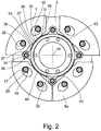
- FIG. 2 is a top view of damper masses system with the damper masses in a position which they occupy when the weight force exceeds the centrifugal force;
- FIGS. 3 a -3 c are schematic views of guide tracks of the mass damper system according to the prior art in which a configuration is carried out for different orders of excitations which are to be ascribed to drives having different numbers of cylinders through different geometric configuration of these guide tracks;
- FIGS. 4 a -4 c are schematic views of guide tracks of the mass damper system according to the invention in which in which a configuration is carried out for different orders of excitations which are to be ascribed to drives having different numbers of cylinders through different dimensioning of coupling elements engaging in these guide tracks;
- FIG. 5 is a schematic view of a powertrain.
- FIG. 1 shows a mass damper system 1 with a damper mass support 3 at which a plurality of damper masses 7 are received.
- the damper masses 7 have in each instance guide tracks 22 formed in pairs for receiving coupling elements 18 which are formed as substantially cylindrical rolling elements 20 .
- the guide tracks 22 are configured in such a way that they allow a radial relative movement of the damper masses 7 with respect to the coupling elements 18 .
- the damper masses 7 have stop sides 43 adjoining their circumferential sides 42 on the radially inner side.
- the guide tracks 13 are guide tracks 13 that extend in a curved manner.
- the guide tracks 13 have in each instance an initial region 14 in which the respective guide track 13 is at the furthest radial distance from a central axis 15 and connection regions 17 that extend opposite to one another with respect to the circumference so as to adjoin both sides of the initial region 14 .
- the guide tracks 22 provided at the damper masses 7 also have a curved shape with, in each instance, an initial region 24 in which the respective guide track 22 has the shortest radial distance from the central axis 15 and with connection regions 25 that extend opposite to one another with respect to the circumference so as to adjoin both sides of the initial region 14 .
- FIG. 1 shows the condition of the damper masses 7 during driving operation when the mass damper system 1 is operated at a speed at which the centrifugal force exceeds the weight force.
- the coupling elements 18 received in the guide tracks 13 and 22 are axially adjacent to one of the guide tracks 22 and engage in each instance in the respective associated guide track 13 .
- the damper masses 7 tend radially outward due to centrifugal force so that the coupling elements 18 are positioned in each instance in the initial region 24 of the respective guide track 22 , i.e., in that region of the guide tracks 22 having the shortest radial distance from the central axis 15 .
- the coupling elements 18 are supported in each instance in the initial region 14 of the guide tracks 13 of the damper mass support 3 , i.e., in that region of the guide tracks 13 having the greatest radial distance from the central axis 15 .
- the damper masses 7 have in each instance at their radially inner ends a geometric formation 28 that has a first contact region 26 in the central portion with respect to the circumference and a second contact region 27 in the outer portions with respect to the circumference.
- the respective first contact region 26 has a center region 37 that divides the first contact region 26 into formation halves 23 .
- this geometric formation 28 cooperates with stops 31 provided radially inside of the damper masses 7 and arranged together at an annular component part 32 .
- the annular component part 32 has in each instance a holder 34 between every two damper masses 7 in circumferential direction.
- the holder 34 encircles a receptacle 11 in each instance so that the holder 34 serves as a stop receptacle 38 in each instance. Accordingly, the annular component part 32 is received at the damper mass support 3 so as to be fixed with respect to rotation relative to it.
- An annular member 33 extending in circumferential direction acts in each instance between every two stop receptacles 38 as a stop profile 40 .
- the stop receptacles 38 and stop profiles 40 together form stops 31 at the annular component part 32 .
- the damper masses 7 tend radially outward under the influence of centrifugal force so that the coupling elements 18 can position themselves in the initial region 24 of the respective guide track 22 of the damper masses 7 .
- torsional vibrations can compel deflections of the damper masses 7 in circumferential direction such that the coupling elements 18 are deflected out of the deflection regions 14 , 24 of the guide tracks 13 , 22 into their connection regions 17 , 25 , the coupling elements 18 are always restored to the initial position under the influence of the centrifugal force as the torsional vibration decays.
- the damper masses 7 fall radially inward and occupy the relative position, shown in FIG. 2 , with respect to one another and with respect to the damper mass support 3 .
- the two damper masses 7 located radially above the central axis 15 fall radially inward until their stop sides 43 come in contact with the associated stop profile 40 of the stop 31 at the annular member 33 of the annular component part 32 with the formation half 23 of the first contact region 26 that is relevant for the movement direction.
- the two damper masses 7 located radially below the central axis 15 likewise fall radially inward until their stop sides 43 come in contact with the associated stop profile 40 of the stop 31 at the annular member 33 of the annular component part 32 with the first contact regions 26 which are formed at the stop sides 43 and which are relevant for the movement direction and, further, until the second circumferential regions 27 of the respective damper masses 7 that are relevant for the movement direction come in contact with the corresponding holders 34 and, accordingly, with the stop receptacles 38 of the annular component part 32 .
- FIGS. 4 a to 4 c respectively, schematically show a guide track 13 of the damper mass support 3 in which a coupling element 18 is received in each instance.
- this is the driving operation described with reference to FIG. 1 without transmission of a torsional vibration, i.e., the coupling element 18 occupies its central position.
- Possible deflection positions of the coupling element 18 in the guide track 13 in circumferential direction lateral to the coupling element 18 shown in solid lines are shown in dashed lines.
- the coupling element 18 can roll out of its central position in the deflection direction on the guide track 13 until a maximum deflection angle ⁇ of about 55° is reached.
- the coupling element 18 will only reach its maximum possible deflection angle when there is a sufficiently strong input of energy as a result of very strong torsional vibrations. Usually, however, the coupling element 18 deflects in smaller angular ranges proceeding from its central position.
- the guide tracks 13 have in circumferential direction a geometric configuration with at least substantially identical radii R that proceed from at least substantially identical piercing points S, while the diameter D 2 of the coupling element 18 in FIG. 4 b is greater than the diameter D 1 of the coupling element 18 in FIG. 4 a , but smaller than the diameter D 3 of the coupling element 18 in FIG. 4 c .
- the coupling element 18 shown in FIG. 4 b is between the coupling elements 18 shown in FIG. 4 a or FIG. 4 c.
- the deflection angle ⁇ covered in so doing remains constant and is preferably about 55°.
- FIG. 5 shows a powertrain such as is suitable for receiving the mass damper system 1 .
- a drive 5 in the form of an internal combustion engine has a crankshaft 54 which is connected, for example, to a coupling arrangement 56 by a drive plate 60 .
- This coupling arrangement 56 can be formed as a flywheel, as a dual-mass flywheel, or as a hydrodynamic clutch device and serves to receive the mass damper system 1 .
- the coupling arrangement 56 is connected to a transmission 62 .
- FIG. 5 shows that the crankshaft 54 of the drive 5 , like the mass damper system 1 , is capable of rotating around the central axis 15 .
Landscapes
- Engineering & Computer Science (AREA)
- General Engineering & Computer Science (AREA)
- Physics & Mathematics (AREA)
- Acoustics & Sound (AREA)
- Aviation & Aerospace Engineering (AREA)
- Mechanical Engineering (AREA)
- Vibration Prevention Devices (AREA)
- Shafts, Cranks, Connecting Bars, And Related Bearings (AREA)
Abstract
Description
Claims (4)
Applications Claiming Priority (4)
| Application Number | Priority Date | Filing Date | Title |
|---|---|---|---|
| DE201310222640 DE102013222640A1 (en) | 2013-11-07 | 2013-11-07 | absorber system |
| DE102013222640.3 | 2013-11-07 | ||
| DE102013222640 | 2013-11-07 | ||
| PCT/EP2014/071416 WO2015067423A1 (en) | 2013-11-07 | 2014-10-07 | Absorber system |
Publications (2)
| Publication Number | Publication Date |
|---|---|
| US20160273614A1 US20160273614A1 (en) | 2016-09-22 |
| US10690220B2 true US10690220B2 (en) | 2020-06-23 |
Family
ID=51663180
Family Applications (1)
| Application Number | Title | Priority Date | Filing Date |
|---|---|---|---|
| US15/034,836 Expired - Fee Related US10690220B2 (en) | 2013-11-07 | 2014-10-07 | Absorber system |
Country Status (4)
| Country | Link |
|---|---|
| US (1) | US10690220B2 (en) |
| CN (1) | CN105658993B (en) |
| DE (1) | DE102013222640A1 (en) |
| WO (1) | WO2015067423A1 (en) |
Families Citing this family (5)
| Publication number | Priority date | Publication date | Assignee | Title |
|---|---|---|---|---|
| DE102013217089A1 (en) * | 2013-08-28 | 2015-03-05 | Zf Friedrichshafen Ag | absorber system |
| FR3038682B1 (en) | 2015-07-06 | 2017-07-28 | Valeo Embrayages | TORSION OSCILLATION DAMPING DEVICE |
| FR3086026B1 (en) * | 2018-09-13 | 2024-03-29 | Valeo Embrayages | PENDULUM DAMPING DEVICE |
| DE102019201875A1 (en) * | 2019-02-13 | 2020-08-13 | Zf Friedrichshafen Ag | Torsional vibration damping arrangement |
| US12222016B2 (en) * | 2022-03-11 | 2025-02-11 | Schaeffler Technologies AG & Co. KG | Segmented centrifugal pendulum absorber mass carrier |
Citations (11)
| Publication number | Priority date | Publication date | Assignee | Title |
|---|---|---|---|---|
| US5495924A (en) * | 1994-07-13 | 1996-03-05 | Quiescence Engineering Corp. | Half-order centrifugal pendulum vibration absorber system |
| DE10059101A1 (en) | 2000-11-28 | 2002-05-29 | Zf Sachs Ag | drive system |
| DE102008057647A1 (en) | 2007-11-29 | 2009-06-04 | Luk Lamellen Und Kupplungsbau Beteiligungs Kg | Power transmission device with a speed adaptive absorber and method for improving the damping behavior |
| US20110088989A1 (en) * | 2008-06-16 | 2011-04-21 | Schaeffler Technologies Gmbh & Co. Kg | Dual clutch with torsional vibration damper |
| DE102010054254A1 (en) | 2009-12-21 | 2011-06-22 | Schaeffler Technologies GmbH & Co. KG, 91074 | Centrifugal pendulum device |
| DE102011076790A1 (en) | 2011-05-31 | 2012-12-06 | Zf Friedrichshafen Ag | Drive system for a vehicle |
| DE10066436B4 (en) | 2000-04-17 | 2013-02-07 | Zf Friedrichshafen Ag | Vibration damper system for fluctuations in motion near critical excitation frequency of drive system has section containing deflection masses mounted on rotating disk and section containing flexible component producing restoring force |
| DE102012219959A1 (en) | 2011-11-28 | 2013-05-29 | Schaeffler Technologies AG & Co. KG | centrifugal pendulum |
| US20140174869A1 (en) * | 2012-12-26 | 2014-06-26 | Aisin Aw Industries Co., Ltd. | Centrifugal-pendulum vibration absorbing device and order setting method for the same |
| US20140352290A1 (en) * | 2012-02-10 | 2014-12-04 | Toyota Jidosha Kabushiki Kaisha | Torsional vibration damping device |
| US20150292594A1 (en) * | 2012-11-26 | 2015-10-15 | Honda Motor Co., Ltd. | Centrifugal pendulum damping device |
Family Cites Families (3)
| Publication number | Priority date | Publication date | Assignee | Title |
|---|---|---|---|---|
| DE102010029464A1 (en) * | 2010-05-28 | 2011-12-01 | Zf Friedrichshafen Ag | Torsionsschwingungsdämpferanordnung and vibration damper device, in particular in a Torsionsschwingungsdämpferanordnung |
| DE102011086436A1 (en) * | 2010-12-20 | 2012-06-21 | Schaeffler Technologies Gmbh & Co. Kg | Torsional vibration damper device for torque transmission device, has flange that is rotatably mounted around central axis, and stop-damping device has mounting section extending in axial direction |
| FR2986591B1 (en) * | 2012-02-07 | 2019-12-20 | Valeo Embrayages | PENDULUM DAMPING DEVICE FOR A MOTOR VEHICLE TRANSMISSION |
-
2013
- 2013-11-07 DE DE201310222640 patent/DE102013222640A1/en not_active Ceased
-
2014
- 2014-10-07 WO PCT/EP2014/071416 patent/WO2015067423A1/en not_active Ceased
- 2014-10-07 CN CN201480058314.5A patent/CN105658993B/en not_active Expired - Fee Related
- 2014-10-07 US US15/034,836 patent/US10690220B2/en not_active Expired - Fee Related
Patent Citations (13)
| Publication number | Priority date | Publication date | Assignee | Title |
|---|---|---|---|---|
| US5495924A (en) * | 1994-07-13 | 1996-03-05 | Quiescence Engineering Corp. | Half-order centrifugal pendulum vibration absorber system |
| DE10066436B4 (en) | 2000-04-17 | 2013-02-07 | Zf Friedrichshafen Ag | Vibration damper system for fluctuations in motion near critical excitation frequency of drive system has section containing deflection masses mounted on rotating disk and section containing flexible component producing restoring force |
| DE10059101A1 (en) | 2000-11-28 | 2002-05-29 | Zf Sachs Ag | drive system |
| DE102008057647A1 (en) | 2007-11-29 | 2009-06-04 | Luk Lamellen Und Kupplungsbau Beteiligungs Kg | Power transmission device with a speed adaptive absorber and method for improving the damping behavior |
| US8161740B2 (en) * | 2007-11-29 | 2012-04-24 | Schaeffler Technologies AG & Co. KG | Force transmission device with a rotational speed adaptive damper and method for improving the damping properties |
| US20110088989A1 (en) * | 2008-06-16 | 2011-04-21 | Schaeffler Technologies Gmbh & Co. Kg | Dual clutch with torsional vibration damper |
| DE102010054254A1 (en) | 2009-12-21 | 2011-06-22 | Schaeffler Technologies GmbH & Co. KG, 91074 | Centrifugal pendulum device |
| DE102011076790A1 (en) | 2011-05-31 | 2012-12-06 | Zf Friedrichshafen Ag | Drive system for a vehicle |
| DE102012219959A1 (en) | 2011-11-28 | 2013-05-29 | Schaeffler Technologies AG & Co. KG | centrifugal pendulum |
| US20150101450A1 (en) * | 2011-11-28 | 2015-04-16 | Schaeffler Technologies Gmbh & Co. Kg | Centrifugal force pendulum |
| US20140352290A1 (en) * | 2012-02-10 | 2014-12-04 | Toyota Jidosha Kabushiki Kaisha | Torsional vibration damping device |
| US20150292594A1 (en) * | 2012-11-26 | 2015-10-15 | Honda Motor Co., Ltd. | Centrifugal pendulum damping device |
| US20140174869A1 (en) * | 2012-12-26 | 2014-06-26 | Aisin Aw Industries Co., Ltd. | Centrifugal-pendulum vibration absorbing device and order setting method for the same |
Also Published As
| Publication number | Publication date |
|---|---|
| CN105658993A (en) | 2016-06-08 |
| WO2015067423A1 (en) | 2015-05-14 |
| CN105658993B (en) | 2017-10-17 |
| DE102013222640A1 (en) | 2015-05-07 |
| US20160273614A1 (en) | 2016-09-22 |
Similar Documents
| Publication | Publication Date | Title |
|---|---|---|
| US9243681B2 (en) | Centrifugal pendulum device | |
| CN104040214B (en) | centrifugal force pendulum | |
| US10690220B2 (en) | Absorber system | |
| US8621957B2 (en) | Hybrid drive train with torsional vibration damper | |
| CN102667228B (en) | Dual mass flywheel and clutch | |
| US9963140B2 (en) | Hybrid module and drive train having such a module | |
| CN103582767B (en) | Drive system for vehicle | |
| US10443680B2 (en) | Centrifugal pendulum device and torsional vibration damper | |
| JP2016514817A (en) | Centrifugal pendulum | |
| US20140013899A1 (en) | Centrifugal pendulum device | |
| US9765839B2 (en) | Torsional vibration damping arrangement, in particular for the powertrain of a vehicle | |
| CN105452712B (en) | centrifugal pendulum | |
| US20170023096A1 (en) | Torsional Vibration Damper Comprising A Damping System, A Damping Device And A Ground Device | |
| CN103180635A (en) | centrifugal pendulum device | |
| US11333218B2 (en) | Centrifugal pendulum device having a pre-stressing element for guiding the cylindrical rollers | |
| US9869366B2 (en) | Apparatus for reducing vibration for vehicles | |
| CN107208742B (en) | Centrifugal force pendulum and use of a centrifugal force pendulum | |
| CN105972152B (en) | Centrifugal force pendulum device | |
| CN105333046B (en) | Centrifuge pendulum damper | |
| CN105765265B (en) | Flywheels for driveline damping devices of motor vehicles | |
| JP2020506352A (en) | Apparatus for damping torsional vibration | |
| CN106461010A (en) | Rotary vibration damper | |
| CN114096761B (en) | Components for a hybrid powertrain of a motor vehicle | |
| CN104662326A (en) | Torsional vibration damper | |
| CN105605152A (en) | single mass flywheel |
Legal Events
| Date | Code | Title | Description |
|---|---|---|---|
| AS | Assignment |
Owner name: ZF FRIEDRICHSHAFEN AG, GERMANY Free format text: ASSIGNMENT OF ASSIGNORS INTEREST;ASSIGNOR:WIRACHOWSKI, MICHAEL;REEL/FRAME:038482/0009 Effective date: 20160125 |
|
| STPP | Information on status: patent application and granting procedure in general |
Free format text: FINAL REJECTION MAILED |
|
| STPP | Information on status: patent application and granting procedure in general |
Free format text: ADVISORY ACTION MAILED |
|
| STPP | Information on status: patent application and granting procedure in general |
Free format text: NON FINAL ACTION MAILED |
|
| STPP | Information on status: patent application and granting procedure in general |
Free format text: RESPONSE TO NON-FINAL OFFICE ACTION ENTERED AND FORWARDED TO EXAMINER |
|
| STPP | Information on status: patent application and granting procedure in general |
Free format text: FINAL REJECTION MAILED |
|
| STCV | Information on status: appeal procedure |
Free format text: NOTICE OF APPEAL FILED |
|
| STCV | Information on status: appeal procedure |
Free format text: APPEAL BRIEF (OR SUPPLEMENTAL BRIEF) ENTERED AND FORWARDED TO EXAMINER |
|
| STPP | Information on status: patent application and granting procedure in general |
Free format text: NOTICE OF ALLOWANCE MAILED -- APPLICATION RECEIVED IN OFFICE OF PUBLICATIONS |
|
| ZAAA | Notice of allowance and fees due |
Free format text: ORIGINAL CODE: NOA |
|
| ZAAB | Notice of allowance mailed |
Free format text: ORIGINAL CODE: MN/=. |
|
| STPP | Information on status: patent application and granting procedure in general |
Free format text: PUBLICATIONS -- ISSUE FEE PAYMENT RECEIVED |
|
| STCF | Information on status: patent grant |
Free format text: PATENTED CASE |
|
| FEPP | Fee payment procedure |
Free format text: MAINTENANCE FEE REMINDER MAILED (ORIGINAL EVENT CODE: REM.); ENTITY STATUS OF PATENT OWNER: LARGE ENTITY |
|
| LAPS | Lapse for failure to pay maintenance fees |
Free format text: PATENT EXPIRED FOR FAILURE TO PAY MAINTENANCE FEES (ORIGINAL EVENT CODE: EXP.); ENTITY STATUS OF PATENT OWNER: LARGE ENTITY |
|
| STCH | Information on status: patent discontinuation |
Free format text: PATENT EXPIRED DUE TO NONPAYMENT OF MAINTENANCE FEES UNDER 37 CFR 1.362 |
|
| FP | Lapsed due to failure to pay maintenance fee |
Effective date: 20240623 |