US10690169B2 - Connecting apparatus and bolt assembly - Google Patents
Connecting apparatus and bolt assembly Download PDFInfo
- Publication number
- US10690169B2 US10690169B2 US15/851,717 US201715851717A US10690169B2 US 10690169 B2 US10690169 B2 US 10690169B2 US 201715851717 A US201715851717 A US 201715851717A US 10690169 B2 US10690169 B2 US 10690169B2
- Authority
- US
- United States
- Prior art keywords
- stopping
- hole
- connector
- elbow
- screw
- Prior art date
- Legal status (The legal status is an assumption and is not a legal conclusion. Google has not performed a legal analysis and makes no representation as to the accuracy of the status listed.)
- Active, expires
Links
- 238000005452 bending Methods 0.000 claims description 9
- 238000010586 diagram Methods 0.000 description 5
- 238000000034 method Methods 0.000 description 3
- 230000015572 biosynthetic process Effects 0.000 description 2
- 230000000712 assembly Effects 0.000 description 1
- 238000000429 assembly Methods 0.000 description 1
- 239000002360 explosive Substances 0.000 description 1
- 230000007246 mechanism Effects 0.000 description 1
- 238000010079 rubber tapping Methods 0.000 description 1
- 230000009466 transformation Effects 0.000 description 1
- 238000003466 welding Methods 0.000 description 1
Images


Classifications
-
- F—MECHANICAL ENGINEERING; LIGHTING; HEATING; WEAPONS; BLASTING
- F16—ENGINEERING ELEMENTS AND UNITS; GENERAL MEASURES FOR PRODUCING AND MAINTAINING EFFECTIVE FUNCTIONING OF MACHINES OR INSTALLATIONS; THERMAL INSULATION IN GENERAL
- F16B—DEVICES FOR FASTENING OR SECURING CONSTRUCTIONAL ELEMENTS OR MACHINE PARTS TOGETHER, e.g. NAILS, BOLTS, CIRCLIPS, CLAMPS, CLIPS OR WEDGES; JOINTS OR JOINTING
- F16B33/00—Features common to bolt and nut
- F16B33/002—Means for preventing rotation of screw-threaded elements
-
- F—MECHANICAL ENGINEERING; LIGHTING; HEATING; WEAPONS; BLASTING
- F16—ENGINEERING ELEMENTS AND UNITS; GENERAL MEASURES FOR PRODUCING AND MAINTAINING EFFECTIVE FUNCTIONING OF MACHINES OR INSTALLATIONS; THERMAL INSULATION IN GENERAL
- F16B—DEVICES FOR FASTENING OR SECURING CONSTRUCTIONAL ELEMENTS OR MACHINE PARTS TOGETHER, e.g. NAILS, BOLTS, CIRCLIPS, CLAMPS, CLIPS OR WEDGES; JOINTS OR JOINTING
- F16B13/00—Dowels or other devices fastened in walls or the like by inserting them in holes made therein for that purpose
- F16B13/04—Dowels or other devices fastened in walls or the like by inserting them in holes made therein for that purpose with parts gripping in the hole or behind the reverse side of the wall after inserting from the front
-
- B—PERFORMING OPERATIONS; TRANSPORTING
- B62—LAND VEHICLES FOR TRAVELLING OTHERWISE THAN ON RAILS
- B62D—MOTOR VEHICLES; TRAILERS
- B62D27/00—Connections between superstructure or understructure sub-units
- B62D27/06—Connections between superstructure or understructure sub-units readily releasable
- B62D27/065—Connections between superstructure or understructure sub-units readily releasable using screwthread
-
- F—MECHANICAL ENGINEERING; LIGHTING; HEATING; WEAPONS; BLASTING
- F16—ENGINEERING ELEMENTS AND UNITS; GENERAL MEASURES FOR PRODUCING AND MAINTAINING EFFECTIVE FUNCTIONING OF MACHINES OR INSTALLATIONS; THERMAL INSULATION IN GENERAL
- F16B—DEVICES FOR FASTENING OR SECURING CONSTRUCTIONAL ELEMENTS OR MACHINE PARTS TOGETHER, e.g. NAILS, BOLTS, CIRCLIPS, CLAMPS, CLIPS OR WEDGES; JOINTS OR JOINTING
- F16B13/00—Dowels or other devices fastened in walls or the like by inserting them in holes made therein for that purpose
- F16B13/04—Dowels or other devices fastened in walls or the like by inserting them in holes made therein for that purpose with parts gripping in the hole or behind the reverse side of the wall after inserting from the front
- F16B13/10—Dowels or other devices fastened in walls or the like by inserting them in holes made therein for that purpose with parts gripping in the hole or behind the reverse side of the wall after inserting from the front with separate gripping parts moved into their final position in relation to the body of the device by a separate operation
-
- F—MECHANICAL ENGINEERING; LIGHTING; HEATING; WEAPONS; BLASTING
- F16—ENGINEERING ELEMENTS AND UNITS; GENERAL MEASURES FOR PRODUCING AND MAINTAINING EFFECTIVE FUNCTIONING OF MACHINES OR INSTALLATIONS; THERMAL INSULATION IN GENERAL
- F16B—DEVICES FOR FASTENING OR SECURING CONSTRUCTIONAL ELEMENTS OR MACHINE PARTS TOGETHER, e.g. NAILS, BOLTS, CIRCLIPS, CLAMPS, CLIPS OR WEDGES; JOINTS OR JOINTING
- F16B35/00—Screw-bolts; Stay-bolts; Screw-threaded studs; Screws; Set screws
- F16B35/04—Screw-bolts; Stay-bolts; Screw-threaded studs; Screws; Set screws with specially-shaped head or shaft in order to fix the bolt on or in an object
- F16B35/06—Specially-shaped heads
-
- F—MECHANICAL ENGINEERING; LIGHTING; HEATING; WEAPONS; BLASTING
- F16—ENGINEERING ELEMENTS AND UNITS; GENERAL MEASURES FOR PRODUCING AND MAINTAINING EFFECTIVE FUNCTIONING OF MACHINES OR INSTALLATIONS; THERMAL INSULATION IN GENERAL
- F16B—DEVICES FOR FASTENING OR SECURING CONSTRUCTIONAL ELEMENTS OR MACHINE PARTS TOGETHER, e.g. NAILS, BOLTS, CIRCLIPS, CLAMPS, CLIPS OR WEDGES; JOINTS OR JOINTING
- F16B37/00—Nuts or like thread-engaging members
-
- F—MECHANICAL ENGINEERING; LIGHTING; HEATING; WEAPONS; BLASTING
- F16—ENGINEERING ELEMENTS AND UNITS; GENERAL MEASURES FOR PRODUCING AND MAINTAINING EFFECTIVE FUNCTIONING OF MACHINES OR INSTALLATIONS; THERMAL INSULATION IN GENERAL
- F16B—DEVICES FOR FASTENING OR SECURING CONSTRUCTIONAL ELEMENTS OR MACHINE PARTS TOGETHER, e.g. NAILS, BOLTS, CIRCLIPS, CLAMPS, CLIPS OR WEDGES; JOINTS OR JOINTING
- F16B5/00—Joining sheets or plates, e.g. panels, to one another or to strips or bars parallel to them
- F16B5/02—Joining sheets or plates, e.g. panels, to one another or to strips or bars parallel to them by means of fastening members using screw-thread
-
- F—MECHANICAL ENGINEERING; LIGHTING; HEATING; WEAPONS; BLASTING
- F16—ENGINEERING ELEMENTS AND UNITS; GENERAL MEASURES FOR PRODUCING AND MAINTAINING EFFECTIVE FUNCTIONING OF MACHINES OR INSTALLATIONS; THERMAL INSULATION IN GENERAL
- F16B—DEVICES FOR FASTENING OR SECURING CONSTRUCTIONAL ELEMENTS OR MACHINE PARTS TOGETHER, e.g. NAILS, BOLTS, CIRCLIPS, CLAMPS, CLIPS OR WEDGES; JOINTS OR JOINTING
- F16B33/00—Features common to bolt and nut
Definitions
- the present disclosure generally relates to connecting structures, and more particular relates to a connecting apparatus and a bolt assembly.
- the connecting assemblies commonly used in the semi closed fastening structure or completely closed fastening structure include: T-shaped bolts and hook bolts.
- T-shaped bolt requires a certain size of the aperture of the connector, and the T-shaped bolt would rotate when fastened, which would has a low mounting efficiency.
- the hook bolt cannot be pulled out along the axial direction of the hook bolt, thus the connectors to be connected could be mounted together.
- the bolt would rotates with the rotation of the nut, resulting in a tedious mounting steps and a low mounting efficiency.
- FIG. 1 is a schematic diagram of a connecting apparatus according to an exemplary embodiment of the present disclosure.
- FIG. 2 is a cross section view of the connecting apparatus according to an exemplary embodiment of FIG. 1 .
- FIG. 3 is a cross section view of the connecting apparatus according to another exemplary embodiment of FIG. 1 .
- FIG. 4 is schematic diagram of the connecting apparatus in a state when the stopping member and the first connector are mounted together via an L-shaped bolt and a nut according to an exemplary embodiment of the present disclosure.
- FIG. 5 is an explosive view of FIG. 4 .
- FIG. 6 is a cross section view of the stopping member and the L-shaped bolt according to an exemplary embodiment of the present disclosure.
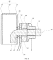
- FIG. 7 is a schematic diagram of a connecting apparatus in a state before the elbow is inserted into the stopping hole according to an exemplary embodiment of the present disclosure.
- FIG. 8 is a schematic diagram of a connecting apparatus according to another exemplary embodiment of the present disclosure.
- FIG. 9 is a schematic diagram of a connecting apparatus in a state when the L-shaped bolt is inserted into the stopping hole of the first connector according to another exemplary embodiment of the present disclosure.
- the connecting apparatus may include a first connector 10 , a second connector L-shaped bolt 40 and a nut 50 fitted about the L-shaped bolt 40 to connect the first connector 10 and the second connector 20 together.
- the first connector 10 and the second connector 20 may be components of an auto. In other embodiments, the first connector 10 and the second connector 20 may also be components of other mechanisms.
- the first connector 10 may have a configuration of plate
- the second connector 20 may have a semi closed structure. Combining with FIG. 2 , the semi closed structure may include a connecting plate 24 defining the second through-hole 22 , a cover plate 26 relative to the connecting plate 2 d and a side wall 28 connecting the connecting plate 24 and the cover plate 26 , the side wall 28 may not completely close the edge of the connecting plate 24 and the cover plate 26 .
- the semi closed structure may include a connecting plate 24 defining the second through-hole 22 , a cover plate 26 relative to the connecting plate 2 d and a side wall 28 connecting the connecting plate 24 and the cover plate 26 , the side wall 28 may not completely close the edge of the connecting plate 24 and the cover plate 26 .
- the second connector 20 may have a completely closed structure, that is, the side wall 28 ′ may extend to close all the edge of the connecting plate 24 and the cover plate 26 .
- both the first connector and the second connector may have configurations of plate.
- the first connector 10 may define a first through-hole 12
- the second connector 20 may define a second through-hole 22
- the stopping member 30 may define a stopping hole 32 .
- the L-shaped bolt 40 may be extended through the first through-hole 12 , the stopping hole 32 and the second through-hole 22 successively and match with the nut 50 to connect the first connector 10 and the second connector 20 together.
- the L-shaped bolt 40 may include a screw 42 and an elbow 14 connecting to the screw 42 .
- the nut 50 may be fitted about the screw 42 and fastened with the screw 42 through threaded connection.
- the elbow 44 may have a stopping surface 440 extending along a lengthwise direction of the elbow 44 .
- the stopping surface 440 may make the cross section of the elbow 44 has a non-circular shape, such as, square, rectangle, triangle, ellipse or other special-shapes.
- the cross section of the elbow 44 having the stopping surface 440 has a square shape with rounded corners.
- the stopping member 30 may be configured to prevent the L-shaped bolt 40 from rotating when the nut 50 is rotated into the screw 42 . On one hand, the stopping member 30 may not rotate relative to the first connector 10 or the second connector 20 , on the other hand, the stopping member 30 may keep the L-shaped bolt 40 from rotating relative to the stopping member 30 .
- the stopping member 30 may include a connecting part 34 and a positioning part 36 arranged on the connecting part 34 .
- the stopping member 30 may be prevented from rotating by the positioning part 36 matching with and cooperating with at least one of the first connector 10 and the second connector 20 .
- the positioning part 36 may bend from an end of the connecting part 34 and be about perpendicular to the connecting part 34 , which may make the stopping member present an “L” configuration.
- the first connector 10 may include a bending part 14 , the positioning part 36 may abut on the bending part 14 , thus the stopping member 30 could not rotate relative to the first connector 10 .
- the bending part may be provided on the second connector, and the positioning part may abut on the bending part of the second connector.
- the positioning part may be a bulge protruding from the connecting part, the surface of the at least one of the first connector and the second connector may define a slot, the bulge may match with the slot to limit the position of the stopping member.
- the connecting part 34 may define the stopping hole 32 .
- the stopping hole 32 may have a non-circular shape, such as, square, rectangle, triangle, ellipse, special-shapes or other shapes which has the stopping function.
- the inner wall of the stopping hole 32 may cooperate with the stopping surface 440 to prevent the L-shaped bolt 40 from rotating along the axis 46 of the screw 42 .
- the stopping hole 32 of this embodiment may present a rectangle shape.
- the shape of the stopping hole 32 may be different from that of the cross section of the elbow 44 , while in other embodiment, the shape of the stopping hole 32 may be the same as that of the cross section of the elbow 44 .
- the cross section of the elbow and the stopping hole may meet a certain relationships.
- a is the length of the square
- r is the radius of the rounded corners
- e is the diagonal length of the square
- b is the width of the stopping hole.
- the length “c” of the rectangle (or the stopping hole 32 ) must be larger than the external bending radius of the L-shaped bolt, such that the L-shaped bolt 40 could turn in the plane which both the screw 42 and the elbow 44 are located in.
- the length of the rectangle could be lengthened, which may not affect the fastening performance and stability after locked.
- the cross section of the elbow and the stopping hole may present other shapes, but the principle of stopping function may be similar to the embodiment mentioned above, which is not recited herein.
- the nut 50 in this embodiment may be an enlarged flange nut, which could enlarge the contact area between the nut 50 and the first connector 10 , so as to increase the anti loose friction force, thereby increasing the locking torque to prevent loosening.
- the elbow 44 of the L-shaped bolt 40 may be perpendicularly inserted into the first through-hole 12 , the stopping hole 32 and the second through-hole successively. Then the L-shaped bolt 40 may be rotated 90° in the plane which both the screw 42 and the elbow 44 are located in, such that the screw 42 of the L-shaped bolt 40 is perpendicular to the plane which the first through-hole 12 are defined in. Finally, the nut 50 is rotated into the screw 42 to fasten the first connector 10 and the second connector 20 together.
- a washer 60 may be arranged between the first connector 10 and the nut 50 .
- the connecting apparatus of the present disclosure could be suitable for mounting a connector on another connector having semi closed structure or completely closed structure, and is more widely used than the T-shaped bolt.
- the stopping hole of the present disclosure is defined by the stopping member, such that the formation of the stopping hole could be simpler, the precision could be guaranteed and the processing cost can be reduced.
- the connecting apparatus of the present disclosure could hide the elbow in the closed structure, therefore the elbow would not be exposed outside of the connecting apparatus.
- the present disclosure may also provide another connecting apparatus, the connecting apparatus may include a first connector 10 ′ defining a first through-hole 12 ′, a second connector 20 defining a second through-hole 22 , an L-shaped bolt 40 including a screw 42 and an elbow 44 connecting to the screw 42 , and a nut 50 fitted about the screw 42 .
- the elbow 44 may have a stopping surface 440 extending along a lengthwise direction of the elbow 44 .
- At least one of the first through-hole 12 ′ and the second through-hole 22 may be a stopping hole, in this embodiment, the first through-hole 12 ′ is the stopping hole.
- the L-shaped bolt 40 may be extended through the first through-hole 12 ′ and the second through-hole 22 and matches with the nut 50 to connect the first connector 10 ′ and the second connector 20 together. When the nut 50 is rotated into the screw 42 , the stopping surface 440 and an inner wall of the stopping hole cooperate with each other to prevent the L-shaped bolt 40 from rotating along an axis 46 of the screw 42 .
- the stopping hole is defined in the first connector 10 ′ or the second connector 20 , thus the stopping member could be omitted.
- the connecting apparatus of the present disclosure could be suitable for mounting a connector on another connector having semi closed structure or completely closed structure. And the connecting apparatus of the present disclosure could hide the elbow in the closed structure, therefore the elbow would not be exposed outside of the connecting apparatus.
- the present disclosure may further provide a bolt assembly, as shown in FIGS. 1-5 , the bolt assembly may include an L-shaped bolt 40 , a nut 50 and a stopping member 30 .
- the L-shaped bolt 40 may include a screw 42 and an elbow 44 connecting to the screw 42 .
- the nut 50 may fit about the screw 42 .
- the stopping member 30 may define a stopping hole 32 .
- the elbow 44 may have a stopping surface 440 extending along a lengthwise direction of the elbow 44 .
- the stopping member 30 may include a connecting part 34 and a positioning part 36 arranged on the connecting part 34 , the connecting part 34 may define the stopping hole 32 , the positioning part 36 may match with at least one of elements to be connected, such as the first connector 10 , to prevent the stopping member 30 from rotating when the nut 50 is rotated.
- the positioning part 36 may bend from an end of the connecting part 34 and abut on a bending part 14 of the first connector 10 .
- the bolt assembly of the present disclosure could be suitable for mounting a connector on another connector having semi closed structure or completely closed structure.
- the stopping hole of the present disclosure is defined by the stopping member, such that the formation of the stopping hole could be simpler, the precision could be guaranteed and the processing cost can be reduced.
- the elbow of the bolt assembly of the present disclosure could be hidden in the closed structure, therefore the elbow would not be exposed outside of the connecting apparatus.
Landscapes
- Engineering & Computer Science (AREA)
- General Engineering & Computer Science (AREA)
- Mechanical Engineering (AREA)
- Chemical & Material Sciences (AREA)
- Combustion & Propulsion (AREA)
- Transportation (AREA)
- Connection Of Plates (AREA)
- Mutual Connection Of Rods And Tubes (AREA)
Abstract
Description
b=a+0.4
or
b≈a+0.4,
and
b<e=√{square root over (2)}(a−2r)+2r
Claims (17)
b=a+0.4
b<e=√{square root over (2)}(a−2r)+2r
b=a+0.4
b<e=√{square root over (2)}(a−2r)+2r
Applications Claiming Priority (3)
| Application Number | Priority Date | Filing Date | Title |
|---|---|---|---|
| CN201611198754 | 2016-12-22 | ||
| CN201611198754.8 | 2016-12-22 | ||
| CN201611198754.8A CN106523499B (en) | 2016-12-22 | 2016-12-22 | A kind of semiclosed fastening structure |
Publications (2)
| Publication Number | Publication Date |
|---|---|
| US20180180084A1 US20180180084A1 (en) | 2018-06-28 |
| US10690169B2 true US10690169B2 (en) | 2020-06-23 |
Family
ID=58340580
Family Applications (1)
| Application Number | Title | Priority Date | Filing Date |
|---|---|---|---|
| US15/851,717 Active 2038-11-13 US10690169B2 (en) | 2016-12-22 | 2017-12-21 | Connecting apparatus and bolt assembly |
Country Status (4)
| Country | Link |
|---|---|
| US (1) | US10690169B2 (en) |
| CN (1) | CN106523499B (en) |
| AU (2) | AU2017279763A1 (en) |
| CA (1) | CA2989901C (en) |
Families Citing this family (5)
| Publication number | Priority date | Publication date | Assignee | Title |
|---|---|---|---|---|
| CN107962156B (en) * | 2017-12-28 | 2024-05-17 | 浙江泉舜流体控制科技有限公司 | Casting mold quick locking and detaching device and application method thereof |
| JP7503012B2 (en) * | 2020-02-26 | 2024-06-19 | 日鉄建材株式会社 | Fastening fittings, fastening structure for corrugated steel plates, and fastening method for corrugated steel plates |
| US12305687B2 (en) * | 2022-10-19 | 2025-05-20 | Gni. Co., Ltd. | L-shaped bolt fastening structure using hole guard |
| KR102813717B1 (en) * | 2022-10-19 | 2025-05-30 | 주식회사 지앤아이 | L-Shaped Bolt Fastening Structure for Upright Fastening |
| CN117090842B (en) * | 2023-10-17 | 2024-01-05 | 维机轨道交通科技(镇江)有限公司 | Pre-buried sleeve with anti-loosening structure, assembling method and assembling equipment |
Citations (15)
| Publication number | Priority date | Publication date | Assignee | Title |
|---|---|---|---|---|
| US1358683A (en) | 1919-08-19 | 1920-11-09 | Stewart John Graham | Grain-shocker |
| US1358688A (en) * | 1920-03-20 | 1920-11-09 | Lyon George Albert | Automobile-buffer attacher |
| US1910249A (en) * | 1931-12-05 | 1933-05-23 | Himmel Brothers Company | Store-front construction |
| GB405203A (en) | 1932-08-22 | 1934-02-01 | Wilhelm Knechten | Leakage or anchor bolt |
| US1955353A (en) * | 1931-11-16 | 1934-04-17 | William R Wiley | Bolt |
| US2379752A (en) * | 1942-05-15 | 1945-07-03 | Frederick W Schultz | Bolt and mounting therefor |
| US3185269A (en) * | 1961-07-31 | 1965-05-25 | Reliance Steel Prod Co | Grating retaining means |
| US3303735A (en) * | 1965-02-01 | 1967-02-14 | Christopher L Fisher | Hook bolt and nut assembly |
| US3463525A (en) * | 1968-04-26 | 1969-08-26 | Schaefer Equip | Securing safety equipment to railroad cars by means of a blind hook bolt |
| US4131204A (en) * | 1975-11-20 | 1978-12-26 | Seiz Corporation | Positive-locking releasable connector for storage rack having vertically adjustable load supports |
| US5509767A (en) * | 1994-03-02 | 1996-04-23 | Alvey, Inc. | Attachment bolt |
| US6077014A (en) * | 1999-11-30 | 2000-06-20 | Gulistan; Bulent | Reliable bolt and clip restrainer assembly |
| US20050192225A1 (en) | 2002-12-18 | 2005-09-01 | Bowen Richard L. | Methods for treating Parkinson's disease |
| WO2012013584A1 (en) | 2010-07-30 | 2012-02-02 | Wolfgang Dietmar Gellermann | Screw connecting system |
| CN205744736U (en) | 2015-11-19 | 2016-11-30 | 广东东箭汽车用品制造有限公司 | A kind of attachment means, automobile pedal bracket and automobile |
Family Cites Families (6)
| Publication number | Priority date | Publication date | Assignee | Title |
|---|---|---|---|---|
| FR2737264B1 (en) * | 1995-07-24 | 1997-10-17 | Brioude Fabrication Sa | INVISIBLE HANGING DEVICE FOR PANELS OR SIDING PLATES AND INTERIOR ARRANGEMENT USING THE SAME |
| CN2558806Y (en) * | 2002-07-02 | 2003-07-02 | 吴宏名 | Bolt adapted for furniture, e.g. table and chair |
| CN2795531Y (en) * | 2004-06-21 | 2006-07-12 | 黄启迪 | Bolt for conveniently and quickly mounting |
| CN201671937U (en) * | 2010-01-28 | 2010-12-15 | 上海宝钢工业检测公司 | Anticorrosion hook bolt |
| CN104728249A (en) * | 2013-12-24 | 2015-06-24 | 鸿富锦精密工业(深圳)有限公司 | Screw combination and fixing device with same |
| CN206338292U (en) * | 2016-12-22 | 2017-07-18 | 广东东箭汽车用品制造有限公司 | A kind of semiclosed fastening structure |
-
2016
- 2016-12-22 CN CN201611198754.8A patent/CN106523499B/en active Active
-
2017
- 2017-12-21 US US15/851,717 patent/US10690169B2/en active Active
- 2017-12-22 CA CA2989901A patent/CA2989901C/en active Active
- 2017-12-22 AU AU2017279763A patent/AU2017279763A1/en not_active Abandoned
-
2019
- 2019-11-26 AU AU2019271947A patent/AU2019271947B2/en active Active
Patent Citations (15)
| Publication number | Priority date | Publication date | Assignee | Title |
|---|---|---|---|---|
| US1358683A (en) | 1919-08-19 | 1920-11-09 | Stewart John Graham | Grain-shocker |
| US1358688A (en) * | 1920-03-20 | 1920-11-09 | Lyon George Albert | Automobile-buffer attacher |
| US1955353A (en) * | 1931-11-16 | 1934-04-17 | William R Wiley | Bolt |
| US1910249A (en) * | 1931-12-05 | 1933-05-23 | Himmel Brothers Company | Store-front construction |
| GB405203A (en) | 1932-08-22 | 1934-02-01 | Wilhelm Knechten | Leakage or anchor bolt |
| US2379752A (en) * | 1942-05-15 | 1945-07-03 | Frederick W Schultz | Bolt and mounting therefor |
| US3185269A (en) * | 1961-07-31 | 1965-05-25 | Reliance Steel Prod Co | Grating retaining means |
| US3303735A (en) * | 1965-02-01 | 1967-02-14 | Christopher L Fisher | Hook bolt and nut assembly |
| US3463525A (en) * | 1968-04-26 | 1969-08-26 | Schaefer Equip | Securing safety equipment to railroad cars by means of a blind hook bolt |
| US4131204A (en) * | 1975-11-20 | 1978-12-26 | Seiz Corporation | Positive-locking releasable connector for storage rack having vertically adjustable load supports |
| US5509767A (en) * | 1994-03-02 | 1996-04-23 | Alvey, Inc. | Attachment bolt |
| US6077014A (en) * | 1999-11-30 | 2000-06-20 | Gulistan; Bulent | Reliable bolt and clip restrainer assembly |
| US20050192225A1 (en) | 2002-12-18 | 2005-09-01 | Bowen Richard L. | Methods for treating Parkinson's disease |
| WO2012013584A1 (en) | 2010-07-30 | 2012-02-02 | Wolfgang Dietmar Gellermann | Screw connecting system |
| CN205744736U (en) | 2015-11-19 | 2016-11-30 | 广东东箭汽车用品制造有限公司 | A kind of attachment means, automobile pedal bracket and automobile |
Also Published As
| Publication number | Publication date |
|---|---|
| CN106523499B (en) | 2019-08-16 |
| US20180180084A1 (en) | 2018-06-28 |
| CA2989901A1 (en) | 2021-02-23 |
| CA2989901C (en) | 2021-02-23 |
| CN106523499A (en) | 2017-03-22 |
| AU2017279763A1 (en) | 2018-07-12 |
| AU2019271947A1 (en) | 2019-12-19 |
| AU2019271947B2 (en) | 2021-02-11 |
Similar Documents
| Publication | Publication Date | Title |
|---|---|---|
| AU2019271947B2 (en) | Connecting Apparatus and Bolt Assembly | |
| US8295060B2 (en) | Mounting apparatus and system for PCI card | |
| US8988821B2 (en) | Hard disk drive enclosure | |
| US20150181726A1 (en) | Mounting apparatus and screw assembly for the same | |
| US9345162B2 (en) | Mounting structure for circuit board | |
| US8602705B2 (en) | Screw assembly | |
| US20150185790A1 (en) | Expansion card chassis assembly | |
| US11692582B2 (en) | Fastener system | |
| US9651058B1 (en) | T-shaped fan blade arm attachment | |
| CN209800513U (en) | An equipment fixture | |
| CN1855641B (en) | Fastener receptacle | |
| US20140048496A1 (en) | Mounting apparatus for electronic device | |
| CN211473879U (en) | Fast-assembling connector, coupling assembling and door and window structure | |
| US3152817A (en) | Connector for joining the ends of pipes to apertured panels | |
| CN104613061B (en) | Hold bent sub and aircraft | |
| US20100212122A1 (en) | Quick buckle assembly for metal case cover | |
| US20140078665A1 (en) | Data storage device assembly | |
| CN204594070U (en) | Compressor rear cover assembly and the refrigerator with this rear shade assembly | |
| CN104764279B (en) | Compressor rear cover component and the refrigerator with the rear shade assembly | |
| US9752613B1 (en) | Hook | |
| US9179563B2 (en) | Electronic device | |
| US20140363999A1 (en) | Peripheral component interconnect (pci) card fixing system | |
| US20150245538A1 (en) | Mounting device for fan and fan assembly | |
| US20220170497A1 (en) | Hook and pin attachment system for attaching two components | |
| US20120314357A1 (en) | Server enclosure |
Legal Events
| Date | Code | Title | Description |
|---|---|---|---|
| AS | Assignment |
Owner name: WINBO-DONGJIAN AUTOMOTIVE TECHNOLOGY CO.,LTD., CHINA Free format text: ASSIGNMENT OF ASSIGNORS INTEREST;ASSIGNORS:CHEN, YONGBO;HUANG, WEI;ZHANG, ZHIHAI;AND OTHERS;REEL/FRAME:044467/0579 Effective date: 20171220 Owner name: WINBO-DONGJIAN AUTOMOTIVE TECHNOLOGY CO.,LTD., CHI Free format text: ASSIGNMENT OF ASSIGNORS INTEREST;ASSIGNORS:CHEN, YONGBO;HUANG, WEI;ZHANG, ZHIHAI;AND OTHERS;REEL/FRAME:044467/0579 Effective date: 20171220 |
|
| FEPP | Fee payment procedure |
Free format text: ENTITY STATUS SET TO UNDISCOUNTED (ORIGINAL EVENT CODE: BIG.); ENTITY STATUS OF PATENT OWNER: LARGE ENTITY |
|
| STPP | Information on status: patent application and granting procedure in general |
Free format text: DOCKETED NEW CASE - READY FOR EXAMINATION |
|
| STPP | Information on status: patent application and granting procedure in general |
Free format text: NON FINAL ACTION MAILED |
|
| STPP | Information on status: patent application and granting procedure in general |
Free format text: RESPONSE TO NON-FINAL OFFICE ACTION ENTERED AND FORWARDED TO EXAMINER |
|
| STPP | Information on status: patent application and granting procedure in general |
Free format text: PUBLICATIONS -- ISSUE FEE PAYMENT VERIFIED |
|
| STCF | Information on status: patent grant |
Free format text: PATENTED CASE |
|
| MAFP | Maintenance fee payment |
Free format text: PAYMENT OF MAINTENANCE FEE, 4TH YEAR, LARGE ENTITY (ORIGINAL EVENT CODE: M1551); ENTITY STATUS OF PATENT OWNER: LARGE ENTITY Year of fee payment: 4 |