US10690126B2 - Dual engine-compressor system - Google Patents
Dual engine-compressor system Download PDFInfo
- Publication number
- US10690126B2 US10690126B2 US16/052,052 US201816052052A US10690126B2 US 10690126 B2 US10690126 B2 US 10690126B2 US 201816052052 A US201816052052 A US 201816052052A US 10690126 B2 US10690126 B2 US 10690126B2
- Authority
- US
- United States
- Prior art keywords
- compressor
- piston
- engine
- pressure chamber
- low
- Prior art date
- Legal status (The legal status is an assumption and is not a legal conclusion. Google has not performed a legal analysis and makes no representation as to the accuracy of the status listed.)
- Active, expires
Links
- 230000009977 dual effect Effects 0.000 title claims abstract description 44
- 239000012530 fluid Substances 0.000 claims abstract description 54
- 238000002485 combustion reaction Methods 0.000 claims abstract description 44
- 235000014676 Phragmites communis Nutrition 0.000 claims abstract description 37
- 238000000034 method Methods 0.000 abstract description 12
- 230000008569 process Effects 0.000 abstract description 12
- 238000007906 compression Methods 0.000 description 11
- 230000006835 compression Effects 0.000 description 10
- 239000000446 fuel Substances 0.000 description 7
- 239000000463 material Substances 0.000 description 5
- ATUOYWHBWRKTHZ-UHFFFAOYSA-N Propane Chemical compound CCC ATUOYWHBWRKTHZ-UHFFFAOYSA-N 0.000 description 4
- VNWKTOKETHGBQD-UHFFFAOYSA-N methane Chemical compound C VNWKTOKETHGBQD-UHFFFAOYSA-N 0.000 description 4
- 230000009471 action Effects 0.000 description 3
- 238000002347 injection Methods 0.000 description 3
- 239000007924 injection Substances 0.000 description 3
- 239000007788 liquid Substances 0.000 description 3
- 238000005461 lubrication Methods 0.000 description 3
- 239000003921 oil Substances 0.000 description 3
- XLYOFNOQVPJJNP-UHFFFAOYSA-N water Substances O XLYOFNOQVPJJNP-UHFFFAOYSA-N 0.000 description 3
- 229920000049 Carbon (fiber) Polymers 0.000 description 2
- 239000004917 carbon fiber Substances 0.000 description 2
- 238000010276 construction Methods 0.000 description 2
- 239000007789 gas Substances 0.000 description 2
- 230000003993 interaction Effects 0.000 description 2
- 230000007246 mechanism Effects 0.000 description 2
- 230000004048 modification Effects 0.000 description 2
- 238000012986 modification Methods 0.000 description 2
- 239000001294 propane Substances 0.000 description 2
- 229910052761 rare earth metal Inorganic materials 0.000 description 2
- 150000002910 rare earth metals Chemical class 0.000 description 2
- 229910000851 Alloy steel Inorganic materials 0.000 description 1
- 229910000831 Steel Inorganic materials 0.000 description 1
- 239000000853 adhesive Substances 0.000 description 1
- 230000001070 adhesive effect Effects 0.000 description 1
- 239000007767 bonding agent Substances 0.000 description 1
- 230000008859 change Effects 0.000 description 1
- 230000005611 electricity Effects 0.000 description 1
- 230000006872 improvement Effects 0.000 description 1
- 230000007774 longterm Effects 0.000 description 1
- 239000010687 lubricating oil Substances 0.000 description 1
- 230000005389 magnetism Effects 0.000 description 1
- 238000004519 manufacturing process Methods 0.000 description 1
- 239000002105 nanoparticle Substances 0.000 description 1
- 239000003345 natural gas Substances 0.000 description 1
- 238000007789 sealing Methods 0.000 description 1
- 239000010959 steel Substances 0.000 description 1
Images


Classifications
-
- F—MECHANICAL ENGINEERING; LIGHTING; HEATING; WEAPONS; BLASTING
- F04—POSITIVE - DISPLACEMENT MACHINES FOR LIQUIDS; PUMPS FOR LIQUIDS OR ELASTIC FLUIDS
- F04B—POSITIVE-DISPLACEMENT MACHINES FOR LIQUIDS; PUMPS
- F04B35/00—Piston pumps specially adapted for elastic fluids and characterised by the driving means to their working members, or by combination with, or adaptation to, specific driving engines or motors, not otherwise provided for
- F04B35/002—Piston pumps specially adapted for elastic fluids and characterised by the driving means to their working members, or by combination with, or adaptation to, specific driving engines or motors, not otherwise provided for driven by internal combustion engines
-
- F—MECHANICAL ENGINEERING; LIGHTING; HEATING; WEAPONS; BLASTING
- F01—MACHINES OR ENGINES IN GENERAL; ENGINE PLANTS IN GENERAL; STEAM ENGINES
- F01B—MACHINES OR ENGINES, IN GENERAL OR OF POSITIVE-DISPLACEMENT TYPE, e.g. STEAM ENGINES
- F01B1/00—Reciprocating-piston machines or engines characterised by number or relative disposition of cylinders or by being built-up from separate cylinder-crankcase elements
- F01B1/08—Reciprocating-piston machines or engines characterised by number or relative disposition of cylinders or by being built-up from separate cylinder-crankcase elements with cylinders arranged oppositely relative to main shaft and of "flat" type
-
- F—MECHANICAL ENGINEERING; LIGHTING; HEATING; WEAPONS; BLASTING
- F01—MACHINES OR ENGINES IN GENERAL; ENGINE PLANTS IN GENERAL; STEAM ENGINES
- F01B—MACHINES OR ENGINES, IN GENERAL OR OF POSITIVE-DISPLACEMENT TYPE, e.g. STEAM ENGINES
- F01B9/00—Reciprocating-piston machines or engines characterised by connections between pistons and main shafts, not specific to groups F01B1/00 - F01B7/00
- F01B9/02—Reciprocating-piston machines or engines characterised by connections between pistons and main shafts, not specific to groups F01B1/00 - F01B7/00 with crankshaft
- F01B9/023—Reciprocating-piston machines or engines characterised by connections between pistons and main shafts, not specific to groups F01B1/00 - F01B7/00 with crankshaft of Bourke-type or Scotch yoke
-
- F—MECHANICAL ENGINEERING; LIGHTING; HEATING; WEAPONS; BLASTING
- F02—COMBUSTION ENGINES; HOT-GAS OR COMBUSTION-PRODUCT ENGINE PLANTS
- F02B—INTERNAL-COMBUSTION PISTON ENGINES; COMBUSTION ENGINES IN GENERAL
- F02B33/00—Engines characterised by provision of pumps for charging or scavenging
- F02B33/02—Engines with reciprocating-piston pumps; Engines with crankcase pumps
-
- F—MECHANICAL ENGINEERING; LIGHTING; HEATING; WEAPONS; BLASTING
- F02—COMBUSTION ENGINES; HOT-GAS OR COMBUSTION-PRODUCT ENGINE PLANTS
- F02B—INTERNAL-COMBUSTION PISTON ENGINES; COMBUSTION ENGINES IN GENERAL
- F02B63/00—Adaptations of engines for driving pumps, hand-held tools or electric generators; Portable combinations of engines with engine-driven devices
- F02B63/06—Adaptations of engines for driving pumps, hand-held tools or electric generators; Portable combinations of engines with engine-driven devices for pumps
-
- F—MECHANICAL ENGINEERING; LIGHTING; HEATING; WEAPONS; BLASTING
- F02—COMBUSTION ENGINES; HOT-GAS OR COMBUSTION-PRODUCT ENGINE PLANTS
- F02B—INTERNAL-COMBUSTION PISTON ENGINES; COMBUSTION ENGINES IN GENERAL
- F02B75/00—Other engines
- F02B75/002—Double acting engines
-
- F—MECHANICAL ENGINEERING; LIGHTING; HEATING; WEAPONS; BLASTING
- F04—POSITIVE - DISPLACEMENT MACHINES FOR LIQUIDS; PUMPS FOR LIQUIDS OR ELASTIC FLUIDS
- F04B—POSITIVE-DISPLACEMENT MACHINES FOR LIQUIDS; PUMPS
- F04B25/00—Multi-stage pumps
- F04B25/005—Multi-stage pumps with two cylinders
-
- F—MECHANICAL ENGINEERING; LIGHTING; HEATING; WEAPONS; BLASTING
- F04—POSITIVE - DISPLACEMENT MACHINES FOR LIQUIDS; PUMPS FOR LIQUIDS OR ELASTIC FLUIDS
- F04B—POSITIVE-DISPLACEMENT MACHINES FOR LIQUIDS; PUMPS
- F04B27/00—Multi-cylinder pumps specially adapted for elastic fluids and characterised by number or arrangement of cylinders
- F04B27/02—Multi-cylinder pumps specially adapted for elastic fluids and characterised by number or arrangement of cylinders having cylinders arranged oppositely relative to main shaft
-
- F—MECHANICAL ENGINEERING; LIGHTING; HEATING; WEAPONS; BLASTING
- F04—POSITIVE - DISPLACEMENT MACHINES FOR LIQUIDS; PUMPS FOR LIQUIDS OR ELASTIC FLUIDS
- F04B—POSITIVE-DISPLACEMENT MACHINES FOR LIQUIDS; PUMPS
- F04B27/00—Multi-cylinder pumps specially adapted for elastic fluids and characterised by number or arrangement of cylinders
- F04B27/04—Multi-cylinder pumps specially adapted for elastic fluids and characterised by number or arrangement of cylinders having cylinders in star- or fan-arrangement
- F04B27/053—Multi-cylinder pumps specially adapted for elastic fluids and characterised by number or arrangement of cylinders having cylinders in star- or fan-arrangement with an actuating element at the inner ends of the cylinders
- F04B27/0536—Multi-cylinder pumps specially adapted for elastic fluids and characterised by number or arrangement of cylinders having cylinders in star- or fan-arrangement with an actuating element at the inner ends of the cylinders with two or more series radial piston-cylinder units
- F04B27/0538—Multi-cylinder pumps specially adapted for elastic fluids and characterised by number or arrangement of cylinders having cylinders in star- or fan-arrangement with an actuating element at the inner ends of the cylinders with two or more series radial piston-cylinder units directly located side-by-side
-
- F—MECHANICAL ENGINEERING; LIGHTING; HEATING; WEAPONS; BLASTING
- F04—POSITIVE - DISPLACEMENT MACHINES FOR LIQUIDS; PUMPS FOR LIQUIDS OR ELASTIC FLUIDS
- F04B—POSITIVE-DISPLACEMENT MACHINES FOR LIQUIDS; PUMPS
- F04B35/00—Piston pumps specially adapted for elastic fluids and characterised by the driving means to their working members, or by combination with, or adaptation to, specific driving engines or motors, not otherwise provided for
- F04B35/01—Piston pumps specially adapted for elastic fluids and characterised by the driving means to their working members, or by combination with, or adaptation to, specific driving engines or motors, not otherwise provided for the means being mechanical
-
- F—MECHANICAL ENGINEERING; LIGHTING; HEATING; WEAPONS; BLASTING
- F04—POSITIVE - DISPLACEMENT MACHINES FOR LIQUIDS; PUMPS FOR LIQUIDS OR ELASTIC FLUIDS
- F04B—POSITIVE-DISPLACEMENT MACHINES FOR LIQUIDS; PUMPS
- F04B39/00—Component parts, details, or accessories, of pumps or pumping systems specially adapted for elastic fluids, not otherwise provided for in, or of interest apart from, groups F04B25/00 - F04B37/00
- F04B39/0005—Component parts, details, or accessories, of pumps or pumping systems specially adapted for elastic fluids, not otherwise provided for in, or of interest apart from, groups F04B25/00 - F04B37/00 adaptations of pistons
-
- F—MECHANICAL ENGINEERING; LIGHTING; HEATING; WEAPONS; BLASTING
- F04—POSITIVE - DISPLACEMENT MACHINES FOR LIQUIDS; PUMPS FOR LIQUIDS OR ELASTIC FLUIDS
- F04B—POSITIVE-DISPLACEMENT MACHINES FOR LIQUIDS; PUMPS
- F04B39/00—Component parts, details, or accessories, of pumps or pumping systems specially adapted for elastic fluids, not otherwise provided for in, or of interest apart from, groups F04B25/00 - F04B37/00
- F04B39/0094—Component parts, details, or accessories, of pumps or pumping systems specially adapted for elastic fluids, not otherwise provided for in, or of interest apart from, groups F04B25/00 - F04B37/00 crankshaft
-
- F—MECHANICAL ENGINEERING; LIGHTING; HEATING; WEAPONS; BLASTING
- F04—POSITIVE - DISPLACEMENT MACHINES FOR LIQUIDS; PUMPS FOR LIQUIDS OR ELASTIC FLUIDS
- F04B—POSITIVE-DISPLACEMENT MACHINES FOR LIQUIDS; PUMPS
- F04B39/00—Component parts, details, or accessories, of pumps or pumping systems specially adapted for elastic fluids, not otherwise provided for in, or of interest apart from, groups F04B25/00 - F04B37/00
- F04B39/10—Adaptations or arrangements of distribution members
- F04B39/1073—Adaptations or arrangements of distribution members the members being reed valves
-
- F—MECHANICAL ENGINEERING; LIGHTING; HEATING; WEAPONS; BLASTING
- F04—POSITIVE - DISPLACEMENT MACHINES FOR LIQUIDS; PUMPS FOR LIQUIDS OR ELASTIC FLUIDS
- F04B—POSITIVE-DISPLACEMENT MACHINES FOR LIQUIDS; PUMPS
- F04B39/00—Component parts, details, or accessories, of pumps or pumping systems specially adapted for elastic fluids, not otherwise provided for in, or of interest apart from, groups F04B25/00 - F04B37/00
- F04B39/12—Casings; Cylinders; Cylinder heads; Fluid connections
- F04B39/128—Crankcases
-
- F—MECHANICAL ENGINEERING; LIGHTING; HEATING; WEAPONS; BLASTING
- F01—MACHINES OR ENGINES IN GENERAL; ENGINE PLANTS IN GENERAL; STEAM ENGINES
- F01B—MACHINES OR ENGINES, IN GENERAL OR OF POSITIVE-DISPLACEMENT TYPE, e.g. STEAM ENGINES
- F01B1/00—Reciprocating-piston machines or engines characterised by number or relative disposition of cylinders or by being built-up from separate cylinder-crankcase elements
- F01B1/12—Separate cylinder-crankcase elements coupled together to form a unit
-
- F—MECHANICAL ENGINEERING; LIGHTING; HEATING; WEAPONS; BLASTING
- F02—COMBUSTION ENGINES; HOT-GAS OR COMBUSTION-PRODUCT ENGINE PLANTS
- F02B—INTERNAL-COMBUSTION PISTON ENGINES; COMBUSTION ENGINES IN GENERAL
- F02B75/00—Other engines
- F02B75/16—Engines characterised by number of cylinders, e.g. single-cylinder engines
- F02B75/18—Multi-cylinder engines
- F02B2075/1804—Number of cylinders
- F02B2075/1808—Number of cylinders two
-
- F—MECHANICAL ENGINEERING; LIGHTING; HEATING; WEAPONS; BLASTING
- F02—COMBUSTION ENGINES; HOT-GAS OR COMBUSTION-PRODUCT ENGINE PLANTS
- F02B—INTERNAL-COMBUSTION PISTON ENGINES; COMBUSTION ENGINES IN GENERAL
- F02B75/00—Other engines
- F02B75/16—Engines characterised by number of cylinders, e.g. single-cylinder engines
- F02B75/18—Multi-cylinder engines
- F02B75/20—Multi-cylinder engines with cylinders all in one line
Definitions
- the present invention is directed to an improved dual engine-compressor system that Is compact and efficient.
- the dual engine-compressor is a straight-line reciprocating device where each engine piston is dual-sided and each compressor piston pressurizes and refills with each stroke.
- the most common engine is the conventional reciprocating piston internal combustion engine in which a reciprocating piston is coupled by a connecting rod to the offset crank pins of a crankshaft.
- the reciprocating motion of the pistons is translated to rotary motion at the crank shaft.
- Power is delivered by the crank shaft to the driven device such as a vehicle or in stationary application to a pump or other device.
- the present invention relates to a new and novel reciprocating device which may be operated either as a combustion engine or as a compressor.
- the device is highly efficient having a high power-to-weight ratio, reduced cylinder friction, reduced vibration, reduced pollution. Lubrication requirements are also minimized.
- the engine design of the invention is extremely versatile and compact and allows for convenient increase in size and horsepower by addition of additional cylinders by addition of basic components with major modifications.
- the design utilizes fewer components than conventional IC engine designs and each cylinder has a piston with cylinder chambers disposed on opposite sides of the piston so the engine essentially “fires” every half stroke.
- the present invention is directed to a dual engine-compressor system.
- the system includes a crankcase enclosing a crankshaft and having at least a first engine cylinder housing disposed on a first side of the crankcase and a first compressor cylinder housing disposed on an opposite second side of the crankcase.
- the first engine cylinder housing defines a first engine bore and the first compressor cylinder housing defines a first compressor bore.
- a first combustion piston is reciprocatingly disposed in the first engine bore and defines alternating combustion chambers within the first engine bore on opposite sides of the first combustion piston.
- a first compressor piston is reciprocatingly disposed in the first compressor bore and defines alternating compressor chambers within the first compressor bore on opposite sides of the first compressor piston.
- a first combustion rod connects the first combustion piston to a first scotch yoke on the crankshaft and a first compressor rod connects the first compressor piston to the first scotch yoke.
- the first combustion rod and the first compressor rod are oriented in a generally linear relationship.
- the alternating compressor chambers in the first compressor bore comprise a low-pressure chamber and a high-pressure chamber.
- the low pressure chamber has a first diameter and the high-pressure chamber has a second diameter that is smaller than the first diameter.
- the first compressor piston has a cylindrical body and a cylindrical cap.
- the cylindrical body has a diameter equal to the second diameter of the high-pressure chamber.
- the cylindrical cap has a diameter equal to the first diameter of the low-pressure chamber.
- a fluid intake is included on the low-pressure chamber of the first compressor housing and an intake reed valve is associated with the fluid intake.
- the intake reed valve is configured to open the fluid intake on an upstroke of the first compressor piston and close the fluid intake on a downstroke of the first compressor piston.
- a low-pressure intake is included through the cylindrical cap of the first compressor piston and a low-pressure reed valve is associated with the low-pressure intake.
- the low-pressure reed valve is configured to open the low-pressure intake on a downstroke of the first compressor piston and close the low-pressure intake on an upstroke of the first compressor piston.
- a high-pressure intake is included through the cylindrical body of the first compressor piston and a high-pressure reed valve is associated with the high-pressure intake.
- the high-pressure reed valve is configured to open the high-pressure intake on an upstroke of the first compressor piston and close the high-pressure intake on a downstroke of the first compressor piston.
- the first compressor piston is configured to reciprocate between an upstroke position, with the first compressor piston substantially within the low-pressure chamber, and a downstroke position, with the first compressor piston substantially within the high-pressure chamber. Movement of the first compressor piston from the downstroke position to the upstroke position causes compressor fluid to be drawn through a fluid intake from outside the first compressor housing through the fluid intake and into the low-pressure chamber—in the area between the fluid intake and the cylindrical cap.
- Movement of the first compressor piston from the upstroke position to the downstroke position causes compressor fluid to be forced through a low-pressure intake from one side of the cylindrical cap to another side of the cylindrical cap, i.e., into the area between the cylindrical cap and the crankcase.
- a second movement of the first compressor piston from the downstroke position to the upstroke position causes compressor fluid to be forced through a high-pressure intake from the low-pressure chamber to the high-pressure chamber, i.e., from the area between the cylindrical cap and the crankcase to the high-pressure chamber.
- a second movement of the first compressor piston from the upstroke position to the downstroke position causes compressor fluid in the high-pressure chamber to be compressed until released through a compressor outlet.
- the first compressor piston may have a plurality of magnets disposed around a perimeter of the piston cylindrical body.
- the first compressor cylinder housing may have a plurality of pick-ups disposed around the high-pressure chamber. In this configuration, each of the plurality of magnets is associated with at least one of the plurality of pick-ups.
- a second engine cylinder housing may be disposed on the first side of the crankcase and define a second engine bor.
- a second combustion piston may be reciprocatingly disposed in the second engine bore and define alternating combustion chambers within the second engine bore on opposite sides of the second combustion piston.
- a second compressor cylinder housing may be disposed on the second side of the crankcase and define a second compressor bore.
- a second compressor piston may be reciprocatingly disposed in the second compressor bore and define alternating compressor chambers within the second compressor bore on opposite sides of the second compressor piston.
- a second combustion rod may connect the second combustion piston to a second scotch yoke on the crankshaft.
- a second compressor rod may connect the second compressor piston to the second scotch yoke.
- the second combustion rod and the second compressor rod are preferably oriented in a generally linear relationship.
- the straight-line reciprocating system uses a scotch yoke or similar rectilinear rotary-motion translation device utilizing dual-chambered engine and compressor cylinders.
- the system operates simultaneously as an engine and as a compressor.
- the system having two engine cylinder housings operates as a four-chamber combustion device and is compatible with various fuels such as gasoline, diesel, natural gas and propane.
- the reciprocating piston device provides high efficiency, high horsepower to weight ratios and reduced emissions.
- the system having two compressor cylinder housings operates as a four-chamber fluid compressor with high efficiency and volumetric capacity for its size.
- FIG. 1 is an elevated perspective, cross-sectional view of the dual engine-compressor system of the present invention
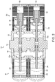
- FIG. 2 is an elevated, cross-sectional view of the dual engine-compressor system of the present invention
- FIG. 3 is a close-up, cross-sectional view of the crankcase and compressor side of the dual engine-compressor system of the present invention
- FIG. 4 is a close-up, cross-sectional view from the opposite angle as FIG. 3 of the crankcase and compressor side of the dual engine-compressor system of the present invention
- FIG. 5 is a cross-sectional, partially exploded view of the compressor cylinder and compressor piston of the dual engine-compressor system of the present invention
- FIG. 6 is a cross-sectional, partially exploded view from the opposite angle of FIG. 5 of the compressor cylinder and compressor piston of the dual engine-compressor system of the present invention
- FIG. 7 is a cross-sectional, perspective view of the compressor cylinder of the dual engine-compressor system of the present invention.
- FIG. 8 is a perspective view of the air intake body for the compressor cylinder of the dual engine-compressor system of the present invention.
- FIG. 9 is a partially exploded, perspective view of the compressor piston of the dual engine-compressor system of the present invention.
- FIG. 10 is an assembled, perspective view of the compressor piston of the dual engine-compressor system of the present invention.
- FIG. 11 is a perspective view of the compressor cylinder with a plurality of pick-ups of the dual engine-compressor system of the present invention.
- FIG. 12 is a cross-sectional, perspective view of the compressor cylinder with a plurality of pick-ups of the dual engine-compressor system of the present invention
- FIG. 13 is a perspective view of a pick-up of the dual engine-compressor system of the present invention.
- FIG. 14 is a perspective view of the compressor piston with a plurality of magnetic discs of the dual engine-compressor system of the present invention.
- FIG. 15 is a perspective view of a preferred embodiment of a reed valve for the fluid intake and low-pressure intake of the dual engine-compressor system of the present invention.
- FIG. 16 is a perspective view of a preferred embodiment of a reed valve for the high-pressure ports of the dual engine-compressor system of the present invention.
- FIG. 17 is a cross-sectional, partially exploded view of the compressor cylinder and compressor piston with the preferred reed valves of the dual engine-compressor system of the present invention
- FIG. 18 is a close-up, partial cut-away view of the crankcase and engine side of the dual engine-compressor system of the present invention.
- FIG. 19 is perspective view of an alternate embodiment of the cylinder from the engine side of the dual engine-compressor system of the present invention.
- FIG. 20 is a perspective view of an alternate embodiment of the combustion piston from the engine side of the dual engine-compressor system of the present invention.
- FIG. 21 is a perspective view of another alternate embodiment of the cylinder from the engine side of the dual engine-compressor system of the present invention.
- the dual engine-compressor system of the present invention is generally referred to by reference numeral 10 in FIGS. 1-4 .
- the main components and the structural relationship of the components of the dual engine-compressor system 10 are most clearly shown in FIGS. 1 and 2 .
- FIGS. 1 and 2 illustrate perspective cross-sectional views of the dual engine-compressor system 10 .
- the system 10 comprises a central crankcase 12 enclosing a crankshaft 14 having connecting journals 14 a , 14 b .
- the crankshaft 14 is connected to linearly disposed piston rods 16 by a scotch yoke 18 or similarly functioning rectilinear, rotary-motion translation device.
- the engine block 20 is disposed on one side of the crankcase 12 .
- the engine block 20 includes one or more engine cylinder housings 22 , each defining an engine bore 24 and containing a reciprocating engine piston 26 connected to one of the piston rods 16 , specifically an engine piston rod 16 a . Since the engine piston 26 is reciprocating, the engine bore 24 defines two combustion chambers 28 a , 28 b —with a single engine bore 24 and piston 26 being capable of two combustion strokes with each reciprocating motion.
- Each engine cylinder housing 22 and bore 24 contain air-fuel intakes (not shown), ignition devices (not shown), and exhaust ports (not shown) as are known in such combustion engines.
- the engine bore 24 includes an exhaust port (not shown) in the middle of its length. As the piston 26 reciprocates through the bore 24 , the exhaust port is alternately covered and exposed relative to one of the combustion chambers 28 a , 28 b on either side of the piston 26 .
- the engine block 20 is preferably configured to time the injection of fuel/air with the movement of the piston 26 as follows. In a corresponding chamber 28 a , 28 b that has just undergone combustion, air is injected just prior to the returning piston 26 covering the exhaust port. In this way, the exhaust gases are pressurized when ejected from the cylinder allowing for muffling of the exhaust.
- the resulting pressure build-up in the chamber 28 a , 28 b keeps the air injector valve closed until the pressure is released through the exhaust port. As the piston 26 moves past the exhaust port, the pressure continues to build-up until the air injection valve is closed. The injection of fuel into the chamber 28 a , 28 b is timed with the compression once the piston 26 has covered the exhaust port.
- a compressor block 30 shown in FIGS. 3 and 4 , is linearly and oppositely disposed on the crankcase 12 in comparison to the engine block 20 .
- the compressor block 30 includes one or more compressor cylinder housings 32 , each defining a compressor bore 34 and containing a reciprocating compressor piston 36 connected to one of the piston rods 16 , specifically a compressor piston rod 16 b . Since the compressor piston 36 is reciprocating, the compressor bore 34 defines two compressor chambers 38 a , 38 b —with a single compressor bore 34 and piston 36 being capable of two compressor strokes with each reciprocating motion.
- the compressor may function as either a gas/air compressor or a liquid/water compressor.
- the engine piston rods 16 a are connected in a straight line with the compressor piston rods 16 b through the scotch yokes 18 on the crankshaft 14 .
- All parts of the system 10 are preferably made from carbon fiber or similar material, except for the crankshaft 14 , which must be made out of steel or similarly strong material for durability.
- the only oil needed is in the crankcase 12 because of the material of the crankshaft 14 .
- the compressor bore 34 includes a low-pressure chamber 38 a and a high-pressure chamber 38 b , wherein the low-pressure chamber 38 a has a first diameter and the high-pressure chamber 38 b has a second diameter larger than the low-pressure chamber 38 a .
- the low-pressure chamber 38 a has a larger volume than the high-pressure chamber 38 b .
- the compressor housing 32 preferably has a plurality of fins 44 provided around the outside. The fins 44 are for dissipating heat generated during the compression cycle. Such heat may arise from friction of the reciprocating pistons 36 against the inner walls of the bore 34 . Heat may also be generated from the repeated and extreme compression of fluid that occurs during the compression process.
- the low pressure chamber 38 a has a fluid intake 40 proximate to the junction between the low-pressure chamber 38 a and the high-pressure chamber 38 b .
- the fluid intake 40 is preferably disposed in an annular ring 42 disposed around the compressor housing 32 , which ring 42 is preferably filled with a porous, annular filter body 42 a ( FIG. 8 ).
- a reed valve 40 a is associated with the fluid intake 40 to provide for selective passage of fluid through the fluid intake 40 .
- the compressor piston 36 comprises a cylindrical body 36 a and a cylindrical cap 36 b .
- the cylindrical body 36 a has a diameter generally the equal to the second diameter of the high-pressure chamber 38 b .
- the cylindrical cap 36 b has a diameter generally equal to the first diameter of the low-pressure chamber 38 a .
- the tolerances between the diameters of the compressor bore 34 and the compressor piston 36 are extremely small so as to create air-tight seals between the pistons 36 and the walls of the bore 34 .
- the compressor piston 36 may also include O-rings 37 around the cylindrical body 36 a and the cylindrical cap 36 b to provide additional sealing.
- the cylindrical cap 36 b includes a low-pressure intake 46 to allow passage of fluid from a bottom-side of the cylindrical cap 36 b to a top-side of the cylindrical cap 36 b .
- a second reed valve 46 a is associated with the low-pressure intake 46 to provide for selective passage of fluid through the low-pressure intake 46 .
- a plurality of ports 48 pass through the compressor piston 36 —from the top-side of the cylindrical cap 36 b to the opposite end of the cylindrical body 36 a —in the high-pressure compressor chamber 38 b .
- a third reed valve 48 a is associated with the plurality of ports 48 on the end of the cylindrical body 36 a to provide for selective passage of fluid through the ports 48 .
- the compressor block 30 undergoes a 4-cycle process.
- the “starting” or bottom position of the compressor piston 36 is where the cylindrical body 36 a is fully inserted into the high-pressure chamber 38 b .
- the 4-cycle process begins with the first step—the first upstroke of withdrawing the cylindrical body 36 a from the high-pressure chamber 38 b , with the cylindrical cap 36 b moving upward through the low-pressure chamber 38 a .
- the first reed valve 40 a activates and opens the fluid intake 40 such that fluid is drawn into the low-pressure chamber 38 a beneath the cylindrical cap 36 b.
- the compressor piston 36 begins the first downstroke—the second step of the 4-cycle process.
- the action of the first downstroke slightly compresses the fluid that was drawn into the low-pressure chamber 38 a beneath the cylindrical cap 38 b , so as to push the reed valve 40 a against the fluid intake 40 so as to close the same.
- the slight compression of the fluid also activates the second reed valve 46 a so as to open the low-pressure intake 46 , allowing the fluid to pass from the area of the low-pressure chamber 38 a beneath the cylindrical cap 36 b to the area of the low-pressure chamber 38 a above the cylindrical cap 36 b .
- all of the fluid that was drawn in through the fluid intake 40 during the first upstroke is now in the low-pressure chamber 38 a above the cylindrical cap 38 b.
- the compressor piston 36 begins the second upstroke—the third step of the 4-cycle process.
- the action of the second upstroke slightly compresses the fluid that was drawn into the low-pressure chamber 38 a above the cylindrical cap 36 b , pushing the second reed valve 46 a against the low-pressure intake 46 so as to close the same.
- the slight compression of the fluid also activates the third reed valve 48 a opening the ports 48 through the compression piston 36 , allowing the fluid to pass from the low-pressure chamber 38 a above the cylindrical cap 26 b to the high-pressure chamber 38 b below the compression piston 36 .
- the upstroke again activates the first reed valve 40 a to open the fluid intake 40 and draw a second volume of fluid into the low-pressure chamber 38 a below the cylindrical cap 36 b , as described above.
- the compressor piston 36 begins the second downstroke—the fourth step of the 4-cycle process.
- the action of the second downstroke compresses the fluid that was drawn into the high-pressure chamber 38 b beneath the compressor piston 36 , pushing the third reed valve 48 a against the ports 48 so as to close the same. Since the volume of fluid that was previously in the low-pressure chamber 38 a with a comparatively larger diameter and volume is now contained in the high-pressure chamber 38 b with a comparatively smaller diameter and volume, the corresponding compression is significantly greater.
- the compressor piston 36 When the compressor piston 36 reaches the bottom position for the second time in a cycle, the fluid in the high-pressure chamber 38 b is fully and significantly compressed. The significantly compressed fluid is then released through a high-pressure outlet 56 in the bottom of the high-pressure chamber 38 b.
- the second downstroke of the cycle also moves the second volume of fluid from the area of the low-pressure chamber 38 a beneath the cylindrical cap 36 b to the area of the low-pressure chamber 38 a above the cylindrical cap 36 b , as described above.
- the parallel 4-cycle process is completed with the third and fourth steps, as described above.
- the 4-cycle process repeats in overlapping parallel processes as long as the crankshaft turns and the pistons reciprocate.
- FIGS. 11-14 illustrate a further improvement to the compressor block 30 .
- the compressor housing 32 is shown to have a plurality of pick-ups 60 disposed around the perimeter, preferably arranged in lines of multiple pick-ups 60 .
- the pick-ups 60 extend through the fins 44 and terminate at the wall of the high-pressure chamber 38 b .
- FIG. 13 shows an individual pick-up 60 as it appears separate from the compressor housing 32 .
- the cylindrical body 36 a of the piston 36 has a plurality of magnetic discs 62 —preferably strong rare-earth magnets—disposed around the piston 36 . These magnetic discs 62 are preferably positioned beneath the pick-ups 60 .
- the movement of the pick-ups 60 relative to the magnetic discs 62 generates electrical current, such that the compressor block 30 not only compresses fluid, but generates electricity.
- FIGS. 15-17 illustrate certain preferred embodiments for the reed valves.
- FIG. 15 shows a reed valve 40 a , 46 a for use with either the fluid intake 40 or the low-pressure intake 46 .
- the reed valve 40 a , 46 a is generally circular to match the shape of the compressor chamber 38 or the cylindrical cap 36 b , and includes a pair of oppositely disposed bolt holes 40 b , 46 b or similar mechanism for attachment.
- reed valve 40 a , 46 a may be attached to either the inner surface of the fluid intake 40 or the low-pressure intake 46 , such attachment is sufficiently loose to allow the reed valve 40 a , 46 a to alternate between an abutting relationship or a spaced relationship with the corresponding intake 40 , 46 . This is how the reed valve 40 a , 46 a works to open or close the corresponding intake 40 , 46 .
- FIG. 16 shows an alternate embodiment reed valve 48 b for use with the high-pressure ports 48 on the compressor piston 36 .
- the reed valve 48 a was shown as a generally circular ring similar to the reed valve 40 a , 46 a in FIG. 15 .
- the alternate embodiment for a reed valve 48 b shown in FIG. 16 is also generally circular, but includes a central support 48 c .
- This central support 48 c includes a bolt hole 48 d or similar mechanism for attachment, that functions as the bolt holes 40 b , 46 b described above.
- FIG. 17 shows a partially exploded cross-section of the compressor housing 32 with the compressor piston 36 and corresponding reed valves 40 a , 46 a , 48 b (the alternate embodiment.
- the inventive system is completely scalable from nano-sized engines to large stationary engines.
- the construction has a reduced demand for lubricating oils and completely eliminates oil from the combustion chambers. It also requires reduced fuel usage when compared to typical combustion engines.
- the system is able to operate either by compression or combustion. It can be either air cooled or water cooled. There is a low production cost because of fewer and less diverse parts.
- the system can also serve as a power plant to drive an electrical generator, while providing both air and liquid compression.
- the system has application in many fields, including, home generators, commercial/industrial generators, standalone use for remote locations, trailer mounted to airport tarmac use, emergency short term and long term use, aviation, un-manned military aviation, ultra-light personal aviation, motor vehicle compressors, engines, motorcycles, kit vehicles, golf carts, heavy diesel engines, marine vessels, military vehicles, agriculture pumps, lifts and winches, and an off-grid power supply.
- the system can be manufactured from carbon fiber housing and crankcase, with a steel alloy crankshaft.
- Fuel injector design allows for use with gasoline, diesel, propane, or practically any other liquid or gaseous fuel.
- the system is low profile with a high power-to-weight ratio. It can be air cooled or water cooled and use pressurized lubrication in the crankcase, with no lubrication required in the cylinders. It can use an electric start/ignition and power system. Calculated performance can reach as much as 1 hp per cubic inch-330 hp @3000 rpm, with usable torque as high as 450 ft-lb @ 2000 rpm.
- FIGS. 18-21 illustrate alternate embodiments for the combustion side 20 of the inventive system 10 .
- the combustion side 20 is outfitted with magnets and pick-ups to create a generator.
- FIG. 18 shows a cylinder housing 22 of the engine side 20 having a plurality of pick-ups 60 arranged around the perimeter of the housing 22 similar to that described above for the compressor housing 32 .
- One of the cylinder housings 22 is shown in partial cut-away to expose the piston 26 inside.
- the piston 26 is shown with a plurality of magnetic rings 62 a surrounding the perimeter of the piston 26 .
- the piston 26 may have two or more ring magnets 62 a .
- the rings 62 a are preferably made from rare earth magnets or similar materials as the magnets 62 described above.
- the ring magnets 62 a allow for easier assembly as the piston 26 can be installed in any orientation without concern for aligning the row of magnets 62 with a row of pickups 60 .
- FIG. 19 shows the combustion cylinder 22 having a plurality of openings 60 a designed to accommodate the pick-ups 60 described above. These openings 60 a allow for the pick-ups 60 to extend through the housing and present a more reliable point of interaction with the magnets 62 a . When installed, the pick-ups 60 must be reliably sealed in the openings 60 a to allow for the pressure experienced in a combustion cylinder 22 .
- FIG. 20 shows an alternate embodiment of a combustion piston 26 showing the ring magnets 62 a .
- the ring magnets 62 a are preferably in multiple positions along the length of the piston 26 .
- the ring magnets 62 a are preferably split into two halves with opposite polarities on the ends. In this way, the split halves of the ring magnets 62 a can be held in place in grooves 64 by their own magnetism, without the need for adhesives or other bonding agents.
- the use of multiple rings magnets 62 a increases the number of interactions between magnets and pick-ups, thus, increasing the electrical generating capacity of the system 10 .
- FIG. 21 shows an alternate embodiment of the combustion cylinder 22 , wherein, instead of a plurality of linearly arranged pick-ups 60 , the cylinder 22 has a plurality of pick-up rings 60 b .
- the plurality of pick-up rings 60 a are disposed around the perimeter of the cylinder and spaced along the length of the cylinder 22 .
- These pick-up rings 60 b can be used in combination with either a plurality of magnets 62 or a plurality of ring magnets 62 a on the piston 26 .
- the ring pick-ups 60 b provide for easier assembly as there is no need to align a row of magnets 62 with a row of pick-ups 60 .
Landscapes
- Engineering & Computer Science (AREA)
- Mechanical Engineering (AREA)
- General Engineering & Computer Science (AREA)
- Chemical & Material Sciences (AREA)
- Combustion & Propulsion (AREA)
- Compressors, Vaccum Pumps And Other Relevant Systems (AREA)
- Compressor (AREA)
Abstract
Description
Claims (13)
Priority Applications (4)
| Application Number | Priority Date | Filing Date | Title |
|---|---|---|---|
| US16/052,052 US10690126B2 (en) | 2018-08-01 | 2018-08-01 | Dual engine-compressor system |
| PCT/US2019/036413 WO2020027920A1 (en) | 2018-08-01 | 2019-06-10 | Dual engine-compressor system |
| US16/878,470 US11053931B2 (en) | 2018-08-01 | 2020-05-19 | Dual engine-compressor system |
| US17/029,596 US20210003121A1 (en) | 2018-08-01 | 2020-09-23 | Process for operating a single-stroke combustion engine |
Applications Claiming Priority (1)
| Application Number | Priority Date | Filing Date | Title |
|---|---|---|---|
| US16/052,052 US10690126B2 (en) | 2018-08-01 | 2018-08-01 | Dual engine-compressor system |
Related Child Applications (1)
| Application Number | Title | Priority Date | Filing Date |
|---|---|---|---|
| US16/878,470 Continuation US11053931B2 (en) | 2018-08-01 | 2020-05-19 | Dual engine-compressor system |
Publications (2)
| Publication Number | Publication Date |
|---|---|
| US20200040880A1 US20200040880A1 (en) | 2020-02-06 |
| US10690126B2 true US10690126B2 (en) | 2020-06-23 |
Family
ID=69227692
Family Applications (2)
| Application Number | Title | Priority Date | Filing Date |
|---|---|---|---|
| US16/052,052 Active 2039-02-08 US10690126B2 (en) | 2018-08-01 | 2018-08-01 | Dual engine-compressor system |
| US16/878,470 Active US11053931B2 (en) | 2018-08-01 | 2020-05-19 | Dual engine-compressor system |
Family Applications After (1)
| Application Number | Title | Priority Date | Filing Date |
|---|---|---|---|
| US16/878,470 Active US11053931B2 (en) | 2018-08-01 | 2020-05-19 | Dual engine-compressor system |
Country Status (2)
| Country | Link |
|---|---|
| US (2) | US10690126B2 (en) |
| WO (1) | WO2020027920A1 (en) |
Citations (14)
| Publication number | Priority date | Publication date | Assignee | Title |
|---|---|---|---|---|
| US2628015A (en) * | 1949-11-09 | 1953-02-10 | Franz J Neugebauer | Engine-driven air compressor |
| US4705460A (en) * | 1985-02-26 | 1987-11-10 | Anton Braun | Bounce chambers for multi-cylinder linear engine compressors |
| US4811558A (en) * | 1981-10-13 | 1989-03-14 | Baugh Benton F | System and method for providing compressed gas |
| US5400751A (en) * | 1993-11-02 | 1995-03-28 | Hurricane Compressors | Monoblock internal combustion engine with air compressor components |
| US5702238A (en) * | 1996-02-06 | 1997-12-30 | Daniel Cecil Simmons | Direct drive gas compressor with vented distance piece |
| US6662775B2 (en) * | 1999-03-23 | 2003-12-16 | Thomas Engine Company, Llc | Integral air compressor for boost air in barrel engine |
| US20050145207A1 (en) * | 1999-03-23 | 2005-07-07 | Thomas Charles R. | Single-ended barrel engine with double-ended, double roller pistons |
| US20070079778A1 (en) * | 2005-10-11 | 2007-04-12 | Atkinson Michael K | Cylinder block for integral gas compressor and internal combustion engine |
| US7503291B2 (en) * | 2005-03-09 | 2009-03-17 | Kiss Engineering, Inc. | Reciprocating device with dual chambered cylinders |
| US20120227389A1 (en) * | 2008-04-16 | 2012-09-13 | Hinderks M V | Reciprocating machine & other devices |
| US20150300242A1 (en) * | 2012-11-22 | 2015-10-22 | Scalzo Automotive Research Pty. Ltd. | Internal combustion engine with asymmetric port timing |
| US20160341187A1 (en) * | 2014-01-31 | 2016-11-24 | Nuovo Pignone Srl | Reciprocating motor-compressor with integrated stirling engine |
| US20170254320A1 (en) * | 2016-03-01 | 2017-09-07 | Rudolf Schulze | Engine Compressor Unit |
| US9957958B2 (en) * | 2015-12-10 | 2018-05-01 | Southwest Research Institute | Reciprocating integral linear engine compressor |
Family Cites Families (9)
| Publication number | Priority date | Publication date | Assignee | Title |
|---|---|---|---|---|
| FR2488344B1 (en) * | 1980-08-05 | 1985-12-27 | Renault | HYDRAULIC GENERATOR WITH FREE PISTON MOTOR |
| DE3500644A1 (en) * | 1985-01-10 | 1986-07-10 | Ficht GmbH, 8011 Kirchseeon | Multicylinder piston engine |
| FI870801A0 (en) * | 1987-02-25 | 1987-02-25 | Toiminimi Kone Sampo | KRAFTAGGREGAT. |
| US4825820A (en) * | 1987-11-09 | 1989-05-02 | Morgan George R | Power system for piston engines & compression devices |
| GB2219671B (en) * | 1988-04-26 | 1993-01-13 | Joseph Frank Kos | Computer controlled optimized hybrid engine |
| US4831972A (en) * | 1988-05-04 | 1989-05-23 | Barnwell Edward A | Internal combustion engine |
| JP4107141B2 (en) * | 2003-02-21 | 2008-06-25 | 株式会社デンソー | Limiter device |
| US9404416B2 (en) * | 2012-03-20 | 2016-08-02 | Gino Kennedy | Generator compressor combination power system |
| KR102071233B1 (en) * | 2014-09-05 | 2020-03-02 | 한온시스템 주식회사 | Compressor, power generating system and method thereof |
-
2018
- 2018-08-01 US US16/052,052 patent/US10690126B2/en active Active
-
2019
- 2019-06-10 WO PCT/US2019/036413 patent/WO2020027920A1/en not_active Ceased
-
2020
- 2020-05-19 US US16/878,470 patent/US11053931B2/en active Active
Patent Citations (14)
| Publication number | Priority date | Publication date | Assignee | Title |
|---|---|---|---|---|
| US2628015A (en) * | 1949-11-09 | 1953-02-10 | Franz J Neugebauer | Engine-driven air compressor |
| US4811558A (en) * | 1981-10-13 | 1989-03-14 | Baugh Benton F | System and method for providing compressed gas |
| US4705460A (en) * | 1985-02-26 | 1987-11-10 | Anton Braun | Bounce chambers for multi-cylinder linear engine compressors |
| US5400751A (en) * | 1993-11-02 | 1995-03-28 | Hurricane Compressors | Monoblock internal combustion engine with air compressor components |
| US5702238A (en) * | 1996-02-06 | 1997-12-30 | Daniel Cecil Simmons | Direct drive gas compressor with vented distance piece |
| US20050145207A1 (en) * | 1999-03-23 | 2005-07-07 | Thomas Charles R. | Single-ended barrel engine with double-ended, double roller pistons |
| US6662775B2 (en) * | 1999-03-23 | 2003-12-16 | Thomas Engine Company, Llc | Integral air compressor for boost air in barrel engine |
| US7503291B2 (en) * | 2005-03-09 | 2009-03-17 | Kiss Engineering, Inc. | Reciprocating device with dual chambered cylinders |
| US20070079778A1 (en) * | 2005-10-11 | 2007-04-12 | Atkinson Michael K | Cylinder block for integral gas compressor and internal combustion engine |
| US20120227389A1 (en) * | 2008-04-16 | 2012-09-13 | Hinderks M V | Reciprocating machine & other devices |
| US20150300242A1 (en) * | 2012-11-22 | 2015-10-22 | Scalzo Automotive Research Pty. Ltd. | Internal combustion engine with asymmetric port timing |
| US20160341187A1 (en) * | 2014-01-31 | 2016-11-24 | Nuovo Pignone Srl | Reciprocating motor-compressor with integrated stirling engine |
| US9957958B2 (en) * | 2015-12-10 | 2018-05-01 | Southwest Research Institute | Reciprocating integral linear engine compressor |
| US20170254320A1 (en) * | 2016-03-01 | 2017-09-07 | Rudolf Schulze | Engine Compressor Unit |
Also Published As
| Publication number | Publication date |
|---|---|
| US20200277946A1 (en) | 2020-09-03 |
| WO2020027920A1 (en) | 2020-02-06 |
| US11053931B2 (en) | 2021-07-06 |
| US20200040880A1 (en) | 2020-02-06 |
Similar Documents
| Publication | Publication Date | Title |
|---|---|---|
| US8191517B2 (en) | Internal combustion engine with dual-chamber cylinder | |
| CN106662007B (en) | free piston engine | |
| US20030183211A1 (en) | Reciprocating internal combustion engine with balancing and supercharging | |
| US5884590A (en) | Two-stroke engine | |
| US8397685B2 (en) | Fuel injection system | |
| US7011051B2 (en) | Hybrid two cycle engine, compressor and pump, and method of operation | |
| US11118503B2 (en) | Internal combustion engine | |
| US20210003121A1 (en) | Process for operating a single-stroke combustion engine | |
| US11053931B2 (en) | Dual engine-compressor system | |
| EP0527146A1 (en) | A double acting, rectangular faced, arc shaped, oscillating piston quadratic internal combustion engine or machine | |
| US5797359A (en) | Stepped piston two-cycle internal combustion engine | |
| US7383798B1 (en) | Highly efficient two-stroke double compression combustion engine | |
| RU2176025C1 (en) | Power-generating heat engine | |
| AU606316B2 (en) | A reciprocating internal combustion engine including a separate gas chamber | |
| US20110030652A1 (en) | Inertial Rotation Internal Combustion Engine | |
| US20260103985A1 (en) | Multi-stage system | |
| WO2024072312A1 (en) | Crankcase scavenged two-stroke engine and handheld power tool | |
| JPS6124528B2 (en) | ||
| HK1235098B (en) | Free piston engine | |
| HK1235098A1 (en) | Free piston engine | |
| TH38369A (en) | Spark-type, four-stroke, internal combustion engine with superconducting charging cylinder. | |
| TH23746B (en) | Spark-type, four-stroke, internal combustion engine with superconducting charging cylinder. | |
| WO1999035398A1 (en) | The crankshaft driven air compressor |
Legal Events
| Date | Code | Title | Description |
|---|---|---|---|
| AS | Assignment |
Owner name: KISS-ENGINEERING INC., CALIFORNIA Free format text: ASSIGNMENT OF ASSIGNORS INTEREST;ASSIGNOR:GAMBLE, CHRISTOPHER L.;REEL/FRAME:046526/0833 Effective date: 20180712 |
|
| FEPP | Fee payment procedure |
Free format text: ENTITY STATUS SET TO UNDISCOUNTED (ORIGINAL EVENT CODE: BIG.); ENTITY STATUS OF PATENT OWNER: SMALL ENTITY |
|
| FEPP | Fee payment procedure |
Free format text: ENTITY STATUS SET TO SMALL (ORIGINAL EVENT CODE: SMAL); ENTITY STATUS OF PATENT OWNER: SMALL ENTITY |
|
| STPP | Information on status: patent application and granting procedure in general |
Free format text: NOTICE OF ALLOWANCE MAILED -- APPLICATION RECEIVED IN OFFICE OF PUBLICATIONS |
|
| STPP | Information on status: patent application and granting procedure in general |
Free format text: PUBLICATIONS -- ISSUE FEE PAYMENT RECEIVED |
|
| STCF | Information on status: patent grant |
Free format text: PATENTED CASE |
|
| MAFP | Maintenance fee payment |
Free format text: PAYMENT OF MAINTENANCE FEE, 4TH YR, SMALL ENTITY (ORIGINAL EVENT CODE: M2551); ENTITY STATUS OF PATENT OWNER: SMALL ENTITY Year of fee payment: 4 |
|
| AS | Assignment |
Owner name: GAMBLE, CHRISTOPHER L., CALIFORNIA Free format text: ASSIGNMENT OF ASSIGNORS INTEREST;ASSIGNOR:KISS-ENGINEERING INC.;REEL/FRAME:069356/0178 Effective date: 20241112 |