US10684097B2 - Thermal gunsights - Google Patents
Thermal gunsights Download PDFInfo
- Publication number
- US10684097B2 US10684097B2 US16/144,546 US201816144546A US10684097B2 US 10684097 B2 US10684097 B2 US 10684097B2 US 201816144546 A US201816144546 A US 201816144546A US 10684097 B2 US10684097 B2 US 10684097B2
- Authority
- US
- United States
- Prior art keywords
- gunsight
- image
- display
- view
- microbolometer
- Prior art date
- Legal status (The legal status is an assumption and is not a legal conclusion. Google has not performed a legal analysis and makes no representation as to the accuracy of the status listed.)
- Active
Links
- 230000004044 response Effects 0.000 claims description 4
- 230000008859 change Effects 0.000 claims description 2
- 238000010586 diagram Methods 0.000 description 9
- 230000008901 benefit Effects 0.000 description 7
- 238000000034 method Methods 0.000 description 6
- 241000282887 Suidae Species 0.000 description 5
- 230000006870 function Effects 0.000 description 5
- 238000012986 modification Methods 0.000 description 4
- 230000004048 modification Effects 0.000 description 4
- 238000012545 processing Methods 0.000 description 4
- 238000010304 firing Methods 0.000 description 3
- 230000008569 process Effects 0.000 description 3
- 241001465754 Metazoa Species 0.000 description 2
- 238000004891 communication Methods 0.000 description 2
- 239000004020 conductor Substances 0.000 description 2
- 239000000758 substrate Substances 0.000 description 2
- 230000008685 targeting Effects 0.000 description 2
- NEWKHUASLBMWRE-UHFFFAOYSA-N 2-methyl-6-(phenylethynyl)pyridine Chemical compound CC1=CC=CC(C#CC=2C=CC=CC=2)=N1 NEWKHUASLBMWRE-UHFFFAOYSA-N 0.000 description 1
- 241000282898 Sus scrofa Species 0.000 description 1
- 230000001133 acceleration Effects 0.000 description 1
- 230000006978 adaptation Effects 0.000 description 1
- 238000004590 computer program Methods 0.000 description 1
- 230000000694 effects Effects 0.000 description 1
- 230000005484 gravity Effects 0.000 description 1
- 230000003760 hair shine Effects 0.000 description 1
- 238000005286 illumination Methods 0.000 description 1
- 238000010348 incorporation Methods 0.000 description 1
- 238000004519 manufacturing process Methods 0.000 description 1
- 230000000422 nocturnal effect Effects 0.000 description 1
- 230000002093 peripheral effect Effects 0.000 description 1
- 244000062645 predators Species 0.000 description 1
- 239000007787 solid Substances 0.000 description 1
- 241000894007 species Species 0.000 description 1
- 230000000007 visual effect Effects 0.000 description 1
Images


Classifications
-
- F—MECHANICAL ENGINEERING; LIGHTING; HEATING; WEAPONS; BLASTING
- F41—WEAPONS
- F41G—WEAPON SIGHTS; AIMING
- F41G1/00—Sighting devices
- F41G1/32—Night sights, e.g. luminescent
- F41G1/34—Night sights, e.g. luminescent combined with light source, e.g. spot light
- F41G1/345—Night sights, e.g. luminescent combined with light source, e.g. spot light for illuminating the sights
-
- F—MECHANICAL ENGINEERING; LIGHTING; HEATING; WEAPONS; BLASTING
- F41—WEAPONS
- F41G—WEAPON SIGHTS; AIMING
- F41G3/00—Aiming or laying means
- F41G3/14—Indirect aiming means
- F41G3/16—Sighting devices adapted for indirect laying of fire
- F41G3/165—Sighting devices adapted for indirect laying of fire using a TV-monitor
-
- F—MECHANICAL ENGINEERING; LIGHTING; HEATING; WEAPONS; BLASTING
- F41—WEAPONS
- F41G—WEAPON SIGHTS; AIMING
- F41G1/00—Sighting devices
- F41G1/32—Night sights, e.g. luminescent
-
- H—ELECTRICITY
- H04—ELECTRIC COMMUNICATION TECHNIQUE
- H04N—PICTORIAL COMMUNICATION, e.g. TELEVISION
- H04N23/00—Cameras or camera modules comprising electronic image sensors; Control thereof
- H04N23/20—Cameras or camera modules comprising electronic image sensors; Control thereof for generating image signals from infrared radiation only
- H04N23/23—Cameras or camera modules comprising electronic image sensors; Control thereof for generating image signals from infrared radiation only from thermal infrared radiation
-
- H—ELECTRICITY
- H04—ELECTRIC COMMUNICATION TECHNIQUE
- H04N—PICTORIAL COMMUNICATION, e.g. TELEVISION
- H04N5/00—Details of television systems
- H04N5/30—Transforming light or analogous information into electric information
- H04N5/33—Transforming infrared radiation
-
- F—MECHANICAL ENGINEERING; LIGHTING; HEATING; WEAPONS; BLASTING
- F41—WEAPONS
- F41G—WEAPON SIGHTS; AIMING
- F41G11/00—Details of sighting or aiming apparatus; Accessories
- F41G11/001—Means for mounting tubular or beam shaped sighting or aiming devices on firearms
- F41G11/003—Mountings with a dove tail element, e.g. "Picatinny rail systems"
-
- F—MECHANICAL ENGINEERING; LIGHTING; HEATING; WEAPONS; BLASTING
- F41—WEAPONS
- F41G—WEAPON SIGHTS; AIMING
- F41G3/00—Aiming or laying means
- F41G3/08—Aiming or laying means with means for compensating for speed, direction, temperature, pressure, or humidity of the atmosphere
Definitions
- a number of weapon-mounted firearm accessories can be used to facilitate aiming the weapon.
- Examples of popular firearm accessories include targeting devices, such as LASER sighting devices, and target illuminators, such as flashlights.
- Firearm mounted flashlights typically attached to a mounting rail and are centered along the bore axis of the firearm.
- a firearm mounted flashlight is useful to light both the surrounding environment as well as possible assailants using only a single hand. This frees the other hand to call the police or fend off an attacker, or alternatively allows a user to keep both hands on the gun for a more secure grip.
- Firearm-mounted lasers may be attached to an accessory rail parallel to the bore axis of a firearm.
- a weapon-mounted laser sighting system has several potential uses. First, a laser can aid in shooting accuracy and speed, particularly in high pressure situations. Further, lasers can aid in shooting at night or indoors in poorly lit environments. Lasers can also be used to safely practice trigger control. Finally, lasers may work as an intimidating deterrent for would-be assailants.
- Laser sights for weapons permit a user to aim a weapon by projecting a light beam onto a target. Laser sights permit a user to quickly aim a weapon without viewing the target through a scope or other sighting device. This also permits the user to aim and shoot from any number of other firing positions, such as permitting the user to shoot from the hip. If the laser sight is properly sighted for the distance and wind conditions involved, a projectile, such as a bullet, arrow or shot, from a weapon will strike the desired target where the light dot generated by the laser sight shines on the target.
- Laser sights are not, however, without problems. For example, although laser sights work well in low light conditions, in bright light conditions laser sights occasionally perform poorly because ambient light can easily overwhelm the dot generated on the target by the laser light source, making the dot difficult or impossible for the user to see. A laser sight also uses a relatively large amount of power, so the battery life for a laser sight is typically relatively short. Also, as with other sights, a laser sight is adjusted or sighted for a particular distance and wind condition. In some combat situations, the laser beam from a laser sight may also act as a targeting beacon for an adversary.
- Thermal gunsights such as thermal riflescopes
- Thermal gunsights may also be particularly useful for hunting animals of the invasive species known as feral pigs or wild boars.
- Feral pigs have become a significant economic problem in the United States, causing an estimated $1.5 billion in annual crop damage alone. Absent any true natural predators, a single pair of feral pigs can reproduce and grow into a population of twenty-five or more pigs in less than 12 months. These animals are known to be highly intelligent and have become nocturnal in areas of human activity. Feral pigs are known to avoid lit areas, even around potential sources of food.
- a gunsight for aiming a firearm may comprise a microbolometer and an objective optic positioned forward of the microbolometer for focusing electromagnetic waves on the microbolometer.
- the objective optic may comprise one or more objective lenses.
- the gunsight may also comprise a display and an eyepiece optic positioned rearward of the display for allowing a user to view the display through the eyepiece optic.
- the eyepiece optic may comprise one or more eyepiece lenses.
- Circuitry of the gunsight is operatively coupled to the microbolometer and the display.
- the circuitry may comprise one or more processors and a non-transitory computer readable medium storing one or more instruction sets.
- the one or more instruction sets include instructions configured to be executed by the one or more processors to cause the gunsight to capture image signals with the microbolometer, the image signals corresponding to a first field of view, the first field of view having a first area.
- instructions are executed by the one or more processors to cause the gunsight to display an image, the image corresponding to a second field of view, the second field of view having a second area, the first area being greater than the second area.
- the processor may analyze the image signals from the microbolometer and identify one or more heat signatures located inside the first field of view and outside of the second field of view.
- the gunsight may display an icon superimposed on the first image, the icon being displayed at an icon position, the icon position being selected based on a location of a selected one of the one or more heat signatures located inside the first field of view and outside of the second field of view.
- a feature and advantage of embodiments is a gunsight that displays an icon (e.g., an arrow or chevron) that points at heat signatures that are within a field of view of the microbolometer but are not in the field of view of a currently displayed image.
- an icon e.g., an arrow or chevron
- a feature and advantage of embodiments is a gunsight that snaps from displaying an image with a higher magnification (e.g., 8 ⁇ , 4 ⁇ , and/or 2 ⁇ ) to displaying an image with a lower magnification (e.g., 1 ⁇ ) when a ballistic event is detected.
- ballistic event refers to the movement of parts or other firearm elements that indicates the operation of the firearm.
- ballistic event refers to the striking of a firing pin with a projectile casing.
- ballistic event refers to ejection of the casing from the firearm after firing.
- ballistic events can be detected via a motion sensor, and used to program operation of the gunsight such that certain gunsight operations correspond with certain operations of the firearm.
- a feature and advantage of embodiments is a gunsight including a power save mode. If the firearm is pointed in a downward direction while the power save mode is activated, the display automatically dims. The display will return to an undimmed level of illumination when the firearm is pointed at a 45 degree angle or greater relative to a horizontal line extending in forward and rearward directions.
- a feature and advantage of embodiments is a gunsight that can be selectively fixed or attached to a mounting rail, such as, for example, a Weaver or Picatinny rail.
- a mounting rail such as, for example, a Weaver or Picatinny rail.
- the position of the gunsight on the firearm can be readily changed.
- the gunsight can also be readily removed from the mounting rail.
- a feature and advantage of embodiments is a gunsight that allows the user to move the location of a reticle or other image upward and/or downward.
- the location of the reticle or other image may be moved upward and/or downward, for example when sighting in the gunsight with a particular weapon.
- the location of the reticle or other image may also be moved upward and/or downward, for example, to account for the downward acceleration on the projectile imparted by gravity, which is often referred to as “bullet drop.”
- a feature and advantage of embodiments is a gunsight that allows the user to move the location of a reticle or other image leftward and/or rightward.
- the location of the reticle or other image may be moved leftward and/or rightward, for example when sighting in the gunsight with a particular weapon.
- the location of the reticle or other image may also be moved leftward and/or rightward, for example, to adjust for left-to-right movement due to wind (sometimes referred to as windage).
- FIG. 1 is a perspective view showing a firearm and a gunsight in accordance with the detailed description.
- FIG. 2 is a perspective view showing the firearm and the gunsight of FIG. 1 from a different point of view. An image that may be viewed through an eyepiece optic of the gunsight is also visible in FIG. 2 .
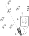
- FIG. 3 is a perspective view showing a gunsight and an image that may be viewed through an eyepiece optic of the gunsight.
- FIG. 4 is a stylized diagram illustrating the border of a field of view sensed by a microbolometer of a gunsight and the border of a field of view of an image displayed on a display of the gunsight.
- FIG. 5 is a stylized depiction of an image displayed on a display of a gunsight.
- FIGS. 6A-6L are stylized depictions of images displayed on a display of a gunsight.
- FIG. 7 is a perspective view of a gunsight in accordance with the detailed description.
- FIG. 8 is a diagram illustrating a gunsight in accordance with the detailed description.
- FIG. 9 is a schematic block diagram illustrating a gunsight in accordance with the detailed description.
- FIG. 10 is a schematic illustration of a microbolometer of a gunsight in accordance with the detailed description.
- FIG. 11 is a schematic diagram illustrating a microbolometer of a gunsight in accordance with the detailed description.
- FIG. 12 is a stylized diagram illustrating a field of view corresponding to a displayed image having 1 ⁇ magnification and another field of view corresponding to a displayed image having 2 ⁇ magnification.
- the diagram of FIG. 12 also shows a field of view corresponding to a displayed image having 4 ⁇ magnification and an additional field of view corresponding to a displayed image having 8 ⁇ magnification.
- FIG. 13 is a reproduction of a mounting rail drawing from Military Standard MIL-STD-1913 dated 3 Feb. 1995.
- FIG. 1 is a perspective view showing a firearm 20 and a gunsight 100 .
- the gunsight 100 is fixed to a mounting rail 22 of the firearm 20 .
- the firearm 20 has a barrel 24 defining a bore 26 .
- the bore 26 extends along a gun bore axis 28 .
- the gun bore axis 28 extends in a forward direction and a rearward direction.
- FIG. 2 is a perspective view showing the firearm and the gunsight of FIG. 1 from a different point of view. An image that may be viewed through an eyepiece optic of the gunsight is also visible in FIG. 2 .
- a gunsight 100 for aiming a firearm may comprise a microbolometer 102 and an objective optic 104 positioned forward of the microbolometer 102 for focusing electromagnetic waves on the microbolometer 102 .
- the objective optic 104 may comprise one or more objective lenses 106 .
- the gunsight 100 also comprises a display 108 and an eyepiece optic 110 positioned rearward of the display 108 for allowing a user to view the display 108 through the eyepiece optic 110 .
- the eyepiece optic may comprise one or more eyepiece lenses 112 .
- Circuitry 114 of the gunsight 100 is operatively coupled to the microbolometer 102 and the display 108 .
- the circuitry 114 may comprise one or more processors 116 and a non-transitory computer readable medium 154 storing one or more instruction sets.
- the one or more instruction sets include instructions configured to be executed by the one or more processors 116 to cause the gunsight 100 to capture image signals with the microbolometer 102 , the image signals corresponding to a first field of view, the first field of view having a first area.
- the instructions executed by the one or more processors 116 also cause the gunsight 100 to display an image on a display 108 .
- the image corresponds to a second field of view in some embodiments.
- the second field of view has a second area smaller than the first area in some embodiments.
- the processor 116 may analyze the image signals from the microbolometer 102 and identify one or more heat signatures located inside the first field of view and outside of the second field of view.
- the gunsight 100 may display an icon superimposed on the first image, the icon being displayed at an icon position, the icon position being selected based on a location of a selected one of the one or more heat signatures located inside the first field of view and outside of the second field of view.
- FIGS. 6A-6L are diagrammatic representations of images 124 that may be presented on the display of a gunsight.
- An icon 160 is displayed at a selected icon location on each image 124 .
- the icon location is selected to provide a user of the gunsight with an indication regarding the next closest target.
- the next closest target refers to a target that is measured in three-dimensions and is the closest to a reference target positioned within the second field of view.
- the next closest target can be measured in a variety of ways. For example, in some embodiments the next closest target is measured as being the closest to the reference target in a two-dimensions. In certain embodiments the next closest target can be measured relative to the position of the shooter or user of the gunsight.
- an image 124 is shown with an icon 160 positioned at a location in an upper right quadrant of the image 124 .
- an icon 160 is positioned at a location in an upper right quadrant of the image 124 if the next closest heat signature is located forward and starboard of the field of view covered by the image.
- an icon 160 is positioned at a location in an upper right quadrant of the image 124 if a selected one of one or more detected heat signatures is located forward and starboard of the field of view covered by the image.
- an image 124 is shown with an icon 160 positioned at a location in an upper left quadrant of the image 124 .
- an icon 160 is positioned at a location in an upper left quadrant of the image 124 if the next closest heat signature is located forward and portward of the field of view covered by the image.
- an icon 160 is positioned at a location in an upper left quadrant of the image 124 if a selected one of one or more detected heat signatures is located forward and portward of the field of view covered by the image.
- an image 124 is shown with an icon 160 positioned at a location in a lower right quadrant of the image 124 .
- an icon 160 is positioned at a location in a lower right quadrant of the image 124 if the next closest heat signature is located rearward and starboard of the field of view covered by the image.
- an icon 160 is positioned at a location in a lower right quadrant of the image 124 if a selected one of one or more detected heat signatures is located rearward and starboard of the field of view covered by the image.
- an image 124 is shown with an icon 160 positioned at a location in a lower left quadrant of the image 124 .
- an icon 160 is positioned at a location in a lower left quadrant of the image 124 if the next closest heat signature is located rearward and portward of the field of view covered by the image.
- an icon 160 is positioned at a location in a lower left quadrant of the image 124 if a selected one of one or more detected heat signatures is located rearward and portward of the field of view covered by the image.
- an image 124 is shown with an icon 160 positioned at a location in a right edge of the image 124 .
- an icon 160 is positioned at a location in a right edge of the image 124 if the next closest heat signature is located starboard of the field of view covered by the image.
- an icon 160 is positioned at a location in a right edge of the image 124 if a selected one of one or more detected heat signatures is located starboard of the field of view covered by the image.
- an image 124 is shown with an icon 160 positioned at a location in a left edge of the image 124 .
- an icon 160 is positioned at a location in a left edge of the image 124 if the next closest heat signature is located portward of the field of view covered by the image.
- an icon 160 is positioned at a location in a left edge of the image 124 if a selected one of one or more detected heat signatures is located portward of the field of view covered by the image.
- an image 124 is shown with an icon 160 positioned at a location in an upper edge of the image 124 .
- an icon 160 is positioned at a location in an upper edge of the image 124 if the next closest heat signature is located forward of the field of view covered by the image.
- an icon 160 is positioned at a location in an upper edge of the image 124 if a selected one of one or more detected heat signatures is located forward of the field of view covered by the image.
- an image 124 is shown with an icon 160 positioned at a location in a lower edge of the image 124 .
- an icon 160 is positioned at a location in a lower edge of the image 124 if the next closest heat signature is located rearward of the field of view covered by the image.
- an icon 160 is positioned at a location in a lower edge of the image 124 if a selected one of one or more detected heat signatures is located rearward of the field of view covered by the image.
- a gunsight 100 for aiming a firearm may comprise a microbolometer 102 and an objective optic 104 positioned forward of the microbolometer 102 for focusing electromagnetic waves on the microbolometer 102 .
- the gunsight 100 also comprises a display 108 and an eyepiece optic 110 positioned rearward of the display 108 for allowing a user to view the display 108 through the eyepiece optic 110 .
- Circuitry 114 of the gunsight 100 is operatively coupled to the microbolometer 102 and the display 108 .
- the circuitry 114 may comprise one or more processors 116 and a non-transitory computer readable medium 154 storing one or more instruction sets.
- the one or more instruction sets include instructions configured to be executed by the one or more processors 116 to cause the gunsight 100 to capture image signals with the microbolometer 102 and display a first image to the user.
- the processor 116 may receive a stream of motion signals from a motion sensing module 158 , such as a accelerometer, gyroscope, or the like, and detect a ballistic event based on analysis of the stream of motion signals.
- the processor 116 may cause the gunsight 100 to display a second image to the user in response to detecting of the ballistic event.
- the first image corresponds to a first magnification
- the second image corresponds to a second magnification
- the first magnification is greater than the second magnification.
- the first image corresponds to a first field of view
- the second image corresponds to a second field of view
- the second field of view is larger than the first field of view.
- FIG. 12 is a stylized diagram illustrating a field of view FV 1 corresponding to a displayed image having 1 ⁇ magnification and another field of view FV 2 corresponding to a displayed image having 2 ⁇ magnification.
- the diagram of FIG. 12 also includes a field of view FV 4 corresponding to a displayed image having 4 ⁇ magnification and another field of view FV 8 corresponding to a displayed image having 8 ⁇ magnification.
- FIGS. 8 and 9 schematically illustrate a gunsight 100 in accordance with this detailed description.
- the gunsight 100 includes a printed wiring board 118 supporting the circuitry 114 .
- the printed wiring board 118 comprises a substrate 120 and the substrate 120 supports a plurality of conductive paths 122 of the circuitry 114 .
- the circuitry 114 comprises the printed wiring board 118 and a plurality of electronic components fixed to the printed wiring board 118 .
- the circuitry 114 may comprise various elements without deviating from the spirit and scope of the present invention.
- the circuitry may comprise combinational logic, a plurality of state machines and a clock that provides a clock signal to the combinational logic and the plurality of state machines.
- Each state machine may comprise state logic circuitry and a state memory.
- the state memory may comprise a plurality of memory elements such as flip-flops.
- the state logic circuitry of the state machine determines the conditions for changing the logical values of bits stored in the state memory. More particularly, the state logic circuitry of the state machine logically combines the binary values of a plurality of inputs with the binary values in the state memory representing the current state to generate a binary number representing the next state.
- the combinational logic circuitry may comprise various elements without deviating from the spirit and scope of the present description.
- combinational logic circuitry may comprise a plurality of discrete electronic components.
- combinational logic circuitry may comprise a plurality of electronic components in the form of an application specific integrated circuit (ASIC).
- ASIC application specific integrated circuit
- electronic components that may be suitable in some applications include logic gates.
- logic gates include, AND gates, NAND gates, OR gates, XOR gates, NOR gates, NOT gates, and the like.
- These logic gates may comprise a plurality of transistors (e.g., transistor-transistor logic (TTL)).
- TTL transistor-transistor logic
- the circuitry 114 may comprise various elements without deviating from the spirit and scope of the present invention.
- the circuitry 114 may comprise a processor, a memory, an input/output interface, a display, and a bus that communicatively couples the processor to the memory, the display and the input/output interface.
- the processor may comprise a collection of one or more logical cores or units for receiving and executing instructions or programs.
- the processor may be configured to receive and execute various routines, programs, objects, components, logic, data structures, and so on to perform particular tasks.
- the memory is a collection of various computer-readable media in the system architecture.
- memory can include, but is not limited to volatile media, non-volatile media, removable media, and non-removable media.
- the memory can include random access memory (RAM), cache memory, read only memory (ROM), flash memory, solid state memory, or other suitable type of memory.
- the memory includes media that is accessible to the electronic circuitry 114 .
- the memory includes computer readable media located locally in the circuitry 114 and/or media located remotely to the circuitry 114 and accessible via a network.
- the memory includes a program product having a group of one or more logical instructions that are executable by the processor to carry out the functions of the various embodiments of the disclosure.
- the bus comprises one or more of any of suitable type of bus structures for communicatively connecting the electronic elements.
- the bus may include a memory bus or memory controller, a peripheral bus, and a processor or local bus using any of a variety of bus architectures.
- the circuitry 114 includes an I/O interface coupled to a processor.
- the I/O interface may facilitate communication between the various components of the circuitry 114 .
- the I/O interface may be communicatively coupled with the projector, the processor and the memory for emitting an output image via the projector.
- the processor generates an output that corresponds to a particular pattern. The processor can transmit this output to the I/O interface which can then translate the processor output into instructions which are compatible with the projector and which result in the projector emitting light corresponding to the pattern.
- the I/O interface facilitates communication with input and output devices for interacting with a user.
- the I/O interface may communicate with one or more devices such, as a user-input device and/or an external display, which enable a user to interact directly with the circuitry 114 .
- the user-input device may comprise a keyboard, one or more push-buttons, a touch screen, or other devices that allows a user to input information.
- the external display may comprise any of a variety of visual displays, such as a viewable screen, a set of viewable symbols or numbers, and so on.
- the gunsight 100 shown in FIG. 8 includes a microbolometer 102 that is electrically coupled to the conductive paths 122 of the printed wiring board 118 by a plurality of wires.
- the gunsight 100 shown in FIG. 8 also includes a display 108 that is electrically coupled to the conductive paths 122 of the printed wiring board 118 by a plurality of wires.
- the gunsight 100 shown in FIG. 8 also includes an objective optic 104 positioned forward of the microbolometer 102 for focusing electromagnetic waves on the microbolometer 102 .
- the objective optic 104 may comprise one or more objective lenses 106 .
- the gunsight 100 shown in FIG. 8 also comprises an eyepiece optic 110 positioned rearward of the display 108 for allowing a user to view the display 108 through the eyepiece optic 110 .
- the eyepiece optic may comprise one or more eyepiece lenses 112 .
- a gunsight 100 for aiming a firearm may comprise a microbolometer 102 and an objective optic 104 positioned forward of the microbolometer 102 for focusing electromagnetic waves on the microbolometer 102 .
- the gunsight 100 also comprises a display 108 and an eyepiece optic 110 positioned rearward of the display 108 for allowing a user to view the display 108 through the eyepiece optic 110 .
- Circuitry 114 of the gunsight 100 is operatively coupled to the microbolometer 102 and the display 108 .
- the circuitry 114 may comprise one or more processors 116 and a non-transitory computer readable medium 154 storing one or more instruction sets.
- the processor 116 may receive a stream of motion signals from a motion sensing module 158 .
- the one or more instruction sets include instructions configured to be executed by the one or more processors 116 to analyze the stream of motion signals from a motion sensing module 158 .
- the processor 116 may determine a present orientation of the bore axis relative to a gravitational pull direction based on a stream of signals from the motion sensing module.
- the processor 116 may also determine an orientation angle of the bore axis relative to a gravitational pull direction based on the stream of signals from the motion sensing module and compare the orientation angle to a predetermined threshold value.
- the processor 116 may cause the gunsight 100 to change an operating state of the display from a first brightness to a second brightness value if the orientation angle is greater than the predetermined threshold value. In some embodiments, the first brightness is greater than the second brightness.
- a microbolometer 102 in accordance with some embodiments comprises a plurality of thermally sensitive pixels 130 arranged to form an array 132 of thermally sensitive pixels 130 .
- the array 132 of thermally sensitive pixels 130 includes a plurality of rows and a plurality of columns.
- Each thermally sensitive pixel may comprise, for example, a sensing element and a switching element. It is noted that the thermally sensitive pixels 130 may be arranged in other patterns without deviating from the spirit and scope of this detailed description.
- the array 132 of thermally sensitive pixels 130 includes a first row 134 A of thermally sensitive pixels 130 aligned along a first row line 136 A, a second row 134 B of thermally sensitive pixels 130 aligned along a second row line 136 B, a third row 134 C of thermally sensitive pixels 130 aligned along a third row line 136 C, and an Mth row 134 M extending along an Mth row line 136 .
- the array 132 of thermally sensitive pixels 130 also includes a first column 138 A of thermally sensitive pixels 130 aligned along a first column line 140 A, a second column 138 B of thermally sensitive pixels 130 aligned along a second column line 140 B, a third column 138 C of thermally sensitive pixels 130 aligned along a third column line 140 C, and an Nth column 138 N of thermally sensitive pixels 130 aligned along an Nth column line 140 N.
- N and M may be, for example, any integer greater than zero.
- the column lines extend in a first direction and the row lines extend in a second direction, the second direction being generally perpendicular to the first direction.
- a microbolometer 102 in accordance with some embodiments comprises a plurality of thermally sensitive pixels 130 arranged to form an array 132 of thermally sensitive pixels 130 .
- the array 132 of thermally sensitive pixels 130 includes a plurality of rows and a plurality of columns.
- each thermally sensitive pixel includes a sensing element 142 and a switching element 144 .
- Each sensing element 142 comprises a variable resistance element 146 having a first terminal and a second terminal in the embodiment of FIG. 11 .
- the first terminal of each variable resistance element 146 is connected to a input conductor 150 .
- the second terminal of each variable resistance element 146 is electrically connected to a switching element 144 in the embodiment of FIG. 11 .
- Each switching element 144 is capable of selectively creating an electrical connection between a respective variable resistance element 146 and a scan conductor 152 .
- a gunsight 100 for aiming a firearm may comprise a microbolometer 102 and an objective optic 104 positioned forward of the microbolometer 102 for focusing electromagnetic waves on the microbolometer 102 .
- the gunsight 100 also comprises a display 108 and an eyepiece optic 110 positioned rearward of the display 108 for allowing a user to view the display 108 through the eyepiece optic 110 .
- Circuitry 114 of the gunsight 100 is operatively coupled to the microbolometer 102 and the display 108 .
- the circuitry 114 may comprise one or more processors 116 and a non-transitory computer readable medium 154 storing one or more instruction sets.
- the processor 116 may receive a stream of motion signals from a motion sensing module 158 and detect a ballistic event based on analysis of the stream of motion signals.
- the processor 116 may also cause a video file to be saved in the non-transitory computer readable medium in response to detecting the ballistic event.
- the video file may correspond to a timeframe, the timeframe spanning from a first time to a second time, the first time being earlier than the ballistic event and a second time being later the ballistic event.
- timeframe has a span of 20 seconds.
- the timeframe extends from 10 seconds before the ballistic event to 10 seconds after the ballistic event.
- the first time is a time that occurred ten seconds before the ballistic event and the second time is a time that occurred ten seconds after the ballistic event.
- the video file may comprise, for example, one of a FFMPEF file, an MPEG file, an AVI file, and a WMV file.
- an upward direction Z and a downward or lower direction ⁇ Z are illustrated using arrows labeled “Z” and “ ⁇ Z,” respectively.
- a forward direction Y and a rearward direction ⁇ Y are illustrated using arrows labeled “Y” and “ ⁇ Y,” respectively.
- a starboard direction X and a port direction ⁇ X are illustrated using arrows labeled “X” and “ ⁇ X,” respectively. The directions illustrated using these arrows are applicable to the apparatus shown and discussed throughout this application.
- the port direction may also be referred to as a left direction and/or the portward direction.
- the starboard direction may also be referred to as a right direction.
- the upward direction is generally opposite the downward direction.
- the upward direction and the downward direction are both generally orthogonal to an XY plane defined by the forward direction and the starboard direction.
- the forward direction is generally opposite the rearward direction.
- the forward direction and the rearward direction are both generally orthogonal to a ZX plane defined by the upward direction and the starboard direction.
- the starboard direction is generally opposite the port direction.
- starboard direction and the port direction are both generally orthogonal to a ZY plane defined by the upward direction and the forward direction.
- direction indicating terms are related to the instant orientation of the object being described. It will also be appreciated that the objects described herein may assume various orientations without deviating from the spirit and scope of this detailed description. Accordingly, direction-indicating terms such as “upwardly,” “downwardly,” “forwardly,” “backwardly,” “portwardly,” and “starboardly,” should not be interpreted to limit the scope of the invention recited in the attached claims.
- One or more embodiments are described herein with reference to program instructions and/or methods, systems, and computer program products for aiming a gunsight according to one or more of the embodiments described herein. It will be understood that these embodiments, may be implemented by computer readable program instructions.
- These computer readable program instructions may be provided to a processor of a general purpose computer, special purpose computer, or other programmable data processing apparatus to produce a machine, such that the instructions, which execute via the processor of the computer or other programmable data processing apparatus, create means for implementing the functions/acts specified in the flowchart and/or block diagram block or blocks.
- These computer readable program instructions may also be stored in a computer readable storage medium that can direct a computer, a programmable data processing apparatus, and/or other devices to function in a particular manner, such that the computer readable storage medium having instructions stored therein comprises an article of manufacture including instructions which implement aspects of the function/act specified in the figures/specification.
- the computer readable program instructions may also be loaded onto a computer, other programmable data processing apparatus, or other device to cause a series of operational steps to be performed on the computer, other programmable apparatus or other device to produce a computer implemented process, such that the instructions which execute on the computer, other programmable apparatus, or other device implement the functions/acts specified herein.
Landscapes
- Engineering & Computer Science (AREA)
- General Engineering & Computer Science (AREA)
- Physics & Mathematics (AREA)
- Optics & Photonics (AREA)
- Multimedia (AREA)
- Signal Processing (AREA)
- Health & Medical Sciences (AREA)
- Toxicology (AREA)
- User Interface Of Digital Computer (AREA)
- Aiming, Guidance, Guns With A Light Source, Armor, Camouflage, And Targets (AREA)
- Eye Examination Apparatus (AREA)
- Radar Systems Or Details Thereof (AREA)
Priority Applications (3)
| Application Number | Priority Date | Filing Date | Title |
|---|---|---|---|
| US16/144,546 US10684097B2 (en) | 2017-09-27 | 2018-09-27 | Thermal gunsights |
| US16/900,709 US11085735B2 (en) | 2017-09-27 | 2020-06-12 | Thermal gunsights |
| US17/364,247 US11662176B2 (en) | 2017-09-27 | 2021-06-30 | Thermal gunsights |
Applications Claiming Priority (2)
| Application Number | Priority Date | Filing Date | Title |
|---|---|---|---|
| US201762563683P | 2017-09-27 | 2017-09-27 | |
| US16/144,546 US10684097B2 (en) | 2017-09-27 | 2018-09-27 | Thermal gunsights |
Related Child Applications (1)
| Application Number | Title | Priority Date | Filing Date |
|---|---|---|---|
| US16/900,709 Continuation US11085735B2 (en) | 2017-09-27 | 2020-06-12 | Thermal gunsights |
Publications (2)
| Publication Number | Publication Date |
|---|---|
| US20190101356A1 US20190101356A1 (en) | 2019-04-04 |
| US10684097B2 true US10684097B2 (en) | 2020-06-16 |
Family
ID=65897342
Family Applications (3)
| Application Number | Title | Priority Date | Filing Date |
|---|---|---|---|
| US16/144,546 Active US10684097B2 (en) | 2017-09-27 | 2018-09-27 | Thermal gunsights |
| US16/900,709 Active US11085735B2 (en) | 2017-09-27 | 2020-06-12 | Thermal gunsights |
| US17/364,247 Active 2038-11-11 US11662176B2 (en) | 2017-09-27 | 2021-06-30 | Thermal gunsights |
Family Applications After (2)
| Application Number | Title | Priority Date | Filing Date |
|---|---|---|---|
| US16/900,709 Active US11085735B2 (en) | 2017-09-27 | 2020-06-12 | Thermal gunsights |
| US17/364,247 Active 2038-11-11 US11662176B2 (en) | 2017-09-27 | 2021-06-30 | Thermal gunsights |
Country Status (4)
| Country | Link |
|---|---|
| US (3) | US10684097B2 (zh) |
| EP (1) | EP3688401B1 (zh) |
| CN (1) | CN111566433B (zh) |
| WO (1) | WO2019067753A1 (zh) |
Cited By (1)
| Publication number | Priority date | Publication date | Assignee | Title |
|---|---|---|---|---|
| US20220011074A1 (en) * | 2017-09-27 | 2022-01-13 | Bushnell Inc. | Thermal gunsights |
Families Citing this family (1)
| Publication number | Priority date | Publication date | Assignee | Title |
|---|---|---|---|---|
| TWD183231S (zh) * | 2015-06-16 | 2017-05-21 | 庇護翼股份有限公司以渦旋光學之名行商 | 瞄準器之部分(二) |
Citations (23)
| Publication number | Priority date | Publication date | Assignee | Title |
|---|---|---|---|---|
| US6871439B1 (en) * | 2003-09-16 | 2005-03-29 | Zyberwear, Inc. | Target-actuated weapon |
| US20070109638A1 (en) | 2005-01-26 | 2007-05-17 | Eotech Acquisition Corp. | Fused thermal and direct view aiming sight |
| US20080163504A1 (en) * | 2007-01-05 | 2008-07-10 | Smith John E | Apparatus and methods for locating and identifying remote objects |
| US7913440B2 (en) * | 2006-05-10 | 2011-03-29 | Swarovski-Optik Kg. | Telescopic sight |
| US7977634B2 (en) * | 2009-02-18 | 2011-07-12 | Dräger Safety AG & Co. KGaA | Thermal imaging camera |
| US20130040268A1 (en) * | 2010-04-23 | 2013-02-14 | Tacktech Pty (Ltd) | Simulated shooting device and system |
| US20140075821A1 (en) * | 2010-10-19 | 2014-03-20 | Danyun Li | Touch display screen used for adjusting and determining the reticle of an electronic firearm sight |
| US8915008B2 (en) * | 2010-08-04 | 2014-12-23 | Trijicon, Inc. | Fused optic |
| US8919650B2 (en) * | 2010-05-06 | 2014-12-30 | Browe, Inc | Optical device |
| US20150153137A1 (en) * | 2013-11-29 | 2015-06-04 | Mbda Deutschland Gmbh | Fire Control Sight, Hand-Held Firearm and a Method For Orienting A Hand-Held Firearm |
| US20150176947A1 (en) | 2013-12-23 | 2015-06-25 | Sergey V. Zaitsev | Bolometric infrared quadrant detectors and uses with firearm applications |
| US9080838B2 (en) * | 2011-07-21 | 2015-07-14 | Bae Systems Information And Electronic Systems Integration Inc. | Active display based targeting and weapon siting system |
| US20150268459A1 (en) * | 2013-03-27 | 2015-09-24 | Jing Zheng | Linear Power Adjustment Mechanism For Telescopic Sights For Firearms |
| US9285189B1 (en) | 2015-04-01 | 2016-03-15 | Huntercraft Limited | Integrated electronic sight and method for calibrating the reticle thereof |
| US9303952B2 (en) * | 2008-05-09 | 2016-04-05 | Gs Development Ab | Combination sight |
| US9377273B1 (en) * | 2014-08-26 | 2016-06-28 | Brian P. Loper | Alignment tool for scope and related methods |
| US9846082B2 (en) * | 2014-02-14 | 2017-12-19 | Fluke Corporation | Infrared thermometer with sighting device and method for measuring temperature of energy zone using same |
| US20180003462A1 (en) * | 2016-07-01 | 2018-01-04 | Vista Outdoor Operations Llc | Multi-function gunsight |
| US20180023921A1 (en) * | 2016-07-19 | 2018-01-25 | Vista Outdoor Operations Llc | Optoelectronic gunsight |
| US20180156569A1 (en) * | 2016-12-01 | 2018-06-07 | Vista Outdoor Operations Llc | Forward grip laser (fgl) |
| US10126099B1 (en) * | 2017-05-11 | 2018-11-13 | Steiner Eoptics, Inc. | Thermal reflex sight |
| USD841112S1 (en) * | 2018-03-05 | 2019-02-19 | Huntercraft Limited | Electronic sight |
| US20190072364A1 (en) * | 2016-05-27 | 2019-03-07 | Vista Outdoor Operations Llc | Pattern configurable reticle |
Family Cites Families (9)
| Publication number | Priority date | Publication date | Assignee | Title |
|---|---|---|---|---|
| CN2655267Y (zh) * | 2003-11-21 | 2004-11-10 | 上海兴禄科技实业有限公司 | 多视点主动式红外夜视仪 |
| US9057583B2 (en) * | 2010-10-28 | 2015-06-16 | Surefire, Llc | Sight system |
| US8793917B2 (en) * | 2011-03-25 | 2014-08-05 | Robert Wayne Russell | Camera mount apparatus and system for a scope |
| CN203518836U (zh) * | 2013-06-08 | 2014-04-02 | 珠海市敏夫光学仪器有限公司 | 一种同一视场内呈现两种不同倍率图像的枪瞄 |
| KR102119659B1 (ko) * | 2013-09-23 | 2020-06-08 | 엘지전자 주식회사 | 영상표시장치 및 그것의 제어 방법 |
| KR102212030B1 (ko) * | 2014-05-26 | 2021-02-04 | 엘지전자 주식회사 | 글래스 타입 단말기 및 이의 제어방법 |
| US9857144B2 (en) | 2014-12-10 | 2018-01-02 | Flir Systems, Inc. | Electronic adaptive reticle systems and methods |
| TWD183231S (zh) * | 2015-06-16 | 2017-05-21 | 庇護翼股份有限公司以渦旋光學之名行商 | 瞄準器之部分(二) |
| US10684097B2 (en) * | 2017-09-27 | 2020-06-16 | Bushnell Inc. | Thermal gunsights |
-
2018
- 2018-09-27 US US16/144,546 patent/US10684097B2/en active Active
- 2018-09-27 EP EP18862415.9A patent/EP3688401B1/en active Active
- 2018-09-27 CN CN201880071959.0A patent/CN111566433B/zh active Active
- 2018-09-27 WO PCT/US2018/053174 patent/WO2019067753A1/en unknown
-
2020
- 2020-06-12 US US16/900,709 patent/US11085735B2/en active Active
-
2021
- 2021-06-30 US US17/364,247 patent/US11662176B2/en active Active
Patent Citations (23)
| Publication number | Priority date | Publication date | Assignee | Title |
|---|---|---|---|---|
| US6871439B1 (en) * | 2003-09-16 | 2005-03-29 | Zyberwear, Inc. | Target-actuated weapon |
| US20070109638A1 (en) | 2005-01-26 | 2007-05-17 | Eotech Acquisition Corp. | Fused thermal and direct view aiming sight |
| US7913440B2 (en) * | 2006-05-10 | 2011-03-29 | Swarovski-Optik Kg. | Telescopic sight |
| US20080163504A1 (en) * | 2007-01-05 | 2008-07-10 | Smith John E | Apparatus and methods for locating and identifying remote objects |
| US9303952B2 (en) * | 2008-05-09 | 2016-04-05 | Gs Development Ab | Combination sight |
| US7977634B2 (en) * | 2009-02-18 | 2011-07-12 | Dräger Safety AG & Co. KGaA | Thermal imaging camera |
| US20130040268A1 (en) * | 2010-04-23 | 2013-02-14 | Tacktech Pty (Ltd) | Simulated shooting device and system |
| US8919650B2 (en) * | 2010-05-06 | 2014-12-30 | Browe, Inc | Optical device |
| US8915008B2 (en) * | 2010-08-04 | 2014-12-23 | Trijicon, Inc. | Fused optic |
| US20140075821A1 (en) * | 2010-10-19 | 2014-03-20 | Danyun Li | Touch display screen used for adjusting and determining the reticle of an electronic firearm sight |
| US9080838B2 (en) * | 2011-07-21 | 2015-07-14 | Bae Systems Information And Electronic Systems Integration Inc. | Active display based targeting and weapon siting system |
| US20150268459A1 (en) * | 2013-03-27 | 2015-09-24 | Jing Zheng | Linear Power Adjustment Mechanism For Telescopic Sights For Firearms |
| US20150153137A1 (en) * | 2013-11-29 | 2015-06-04 | Mbda Deutschland Gmbh | Fire Control Sight, Hand-Held Firearm and a Method For Orienting A Hand-Held Firearm |
| US20150176947A1 (en) | 2013-12-23 | 2015-06-25 | Sergey V. Zaitsev | Bolometric infrared quadrant detectors and uses with firearm applications |
| US9846082B2 (en) * | 2014-02-14 | 2017-12-19 | Fluke Corporation | Infrared thermometer with sighting device and method for measuring temperature of energy zone using same |
| US9377273B1 (en) * | 2014-08-26 | 2016-06-28 | Brian P. Loper | Alignment tool for scope and related methods |
| US9285189B1 (en) | 2015-04-01 | 2016-03-15 | Huntercraft Limited | Integrated electronic sight and method for calibrating the reticle thereof |
| US20190072364A1 (en) * | 2016-05-27 | 2019-03-07 | Vista Outdoor Operations Llc | Pattern configurable reticle |
| US20180003462A1 (en) * | 2016-07-01 | 2018-01-04 | Vista Outdoor Operations Llc | Multi-function gunsight |
| US20180023921A1 (en) * | 2016-07-19 | 2018-01-25 | Vista Outdoor Operations Llc | Optoelectronic gunsight |
| US20180156569A1 (en) * | 2016-12-01 | 2018-06-07 | Vista Outdoor Operations Llc | Forward grip laser (fgl) |
| US10126099B1 (en) * | 2017-05-11 | 2018-11-13 | Steiner Eoptics, Inc. | Thermal reflex sight |
| USD841112S1 (en) * | 2018-03-05 | 2019-02-19 | Huntercraft Limited | Electronic sight |
Cited By (2)
| Publication number | Priority date | Publication date | Assignee | Title |
|---|---|---|---|---|
| US20220011074A1 (en) * | 2017-09-27 | 2022-01-13 | Bushnell Inc. | Thermal gunsights |
| US11662176B2 (en) * | 2017-09-27 | 2023-05-30 | Bushnell Inc. | Thermal gunsights |
Also Published As
| Publication number | Publication date |
|---|---|
| US20210003367A1 (en) | 2021-01-07 |
| US11662176B2 (en) | 2023-05-30 |
| US20190101356A1 (en) | 2019-04-04 |
| US11085735B2 (en) | 2021-08-10 |
| US20220011074A1 (en) | 2022-01-13 |
| WO2019067753A1 (en) | 2019-04-04 |
| CN111566433B (zh) | 2023-03-07 |
| EP3688401A4 (en) | 2021-10-13 |
| EP3688401A1 (en) | 2020-08-05 |
| CN111566433A (zh) | 2020-08-21 |
| EP3688401B1 (en) | 2023-08-23 |
Similar Documents
| Publication | Publication Date | Title |
|---|---|---|
| US12031796B2 (en) | Optical system with cant indication | |
| US10921091B2 (en) | Holographic weapon sight | |
| US9857144B2 (en) | Electronic adaptive reticle systems and methods | |
| KR100681784B1 (ko) | 전자식 화기 조준기 및 그 작동 방법 | |
| BR112021014084A2 (pt) | Elemento óptico de visualização com sistema de contador de disparo | |
| KR20230019426A (ko) | 인에이블러 인터페이스를 구비하는 시야 광학체 | |
| US11662176B2 (en) | Thermal gunsights | |
| US9267761B2 (en) | Video camera gun barrel mounting and programming system | |
| CN110770529B (zh) | 靶向系统 | |
| US20180039061A1 (en) | Apparatus and methods to generate images and display data using optical device | |
| US20220326596A1 (en) | Imaging system for firearm | |
| US11022403B2 (en) | Targeting system | |
| US11054217B2 (en) | Cant sensitivity level | |
| EP2778597A1 (en) | Compact thermal aiming sight | |
| TWI647421B (zh) | 目標獲取裝置及其系統 | |
| US20180023921A1 (en) | Optoelectronic gunsight | |
| EP2746716A1 (en) | Optical device including a mode for grouping shots for use with precision guided firearms | |
| RU59231U1 (ru) | Прицельный комплекс | |
| EP2950034A1 (en) | A method and an apparatus for target aiming | |
| UA26704U (en) | Appliance for aiming and target shooting from fire arms |
Legal Events
| Date | Code | Title | Description |
|---|---|---|---|
| FEPP | Fee payment procedure |
Free format text: ENTITY STATUS SET TO UNDISCOUNTED (ORIGINAL EVENT CODE: BIG.); ENTITY STATUS OF PATENT OWNER: LARGE ENTITY |
|
| AS | Assignment |
Owner name: WELLS FARGO BANK, NATIONAL ASSOCIATION, AS ADMINIS Free format text: TERM LOAN INTELLECTUAL PROPERTY SECURITY AGREEMENT SUPPLEMENT;ASSIGNORS:BELL SPORTS, INC.;BUSHNELL HOLDINGS, INC.;BUSHNELL INC.;AND OTHERS;REEL/FRAME:048413/0051 Effective date: 20190222 Owner name: WELLS FARGO BANK, NATIONAL ASSOCIATION, AS ADMINISTRATIVE AGENT, CALIFORNIA Free format text: TERM LOAN INTELLECTUAL PROPERTY SECURITY AGREEMENT SUPPLEMENT;ASSIGNORS:BELL SPORTS, INC.;BUSHNELL HOLDINGS, INC.;BUSHNELL INC.;AND OTHERS;REEL/FRAME:048413/0051 Effective date: 20190222 |
|
| AS | Assignment |
Owner name: WELLS FARGO BANK, NATIONAL ASSOCIATION, AS ADMINIS Free format text: ABL INTELLECTUAL PROPERTY SECURITY AGREEMENT SUPPLEMENT;ASSIGNORS:BELL SPORTS, INC.;BUSHNELL HOLDINGS, INC.;BUSHNELL INC.;AND OTHERS;REEL/FRAME:048421/0556 Effective date: 20190222 Owner name: WELLS FARGO BANK, NATIONAL ASSOCIATION, AS ADMINISTRATIVE AGENT, CALIFORNIA Free format text: ABL INTELLECTUAL PROPERTY SECURITY AGREEMENT SUPPLEMENT;ASSIGNORS:BELL SPORTS, INC.;BUSHNELL HOLDINGS, INC.;BUSHNELL INC.;AND OTHERS;REEL/FRAME:048421/0556 Effective date: 20190222 |
|
| STPP | Information on status: patent application and granting procedure in general |
Free format text: DOCKETED NEW CASE - READY FOR EXAMINATION |
|
| AS | Assignment |
Owner name: GACP FINANCE CO., LLC, CALIFORNIA Free format text: SECURITY INTEREST;ASSIGNORS:BELL SPORTS, INC.;BUSHNELL HOLDINGS, INC.;BUSHNELL INC.;AND OTHERS;REEL/FRAME:049515/0590 Effective date: 20190312 |
|
| AS | Assignment |
Owner name: VISTA OUTDOOR OPERATIONS LLC, MINNESOTA Free format text: RELEASE BY SECURED PARTY;ASSIGNOR:WELLS FARGO BANK, NATIONAL ASSOCIATION, AS ADMINISTRATIVE AGENT;REEL/FRAME:049724/0931 Effective date: 20190710 Owner name: C PREME LIMITED LLC, CALIFORNIA Free format text: RELEASE BY SECURED PARTY;ASSIGNOR:WELLS FARGO BANK, NATIONAL ASSOCIATION, AS ADMINISTRATIVE AGENT;REEL/FRAME:049724/0931 Effective date: 20190710 Owner name: NORTHSTAR OUTDOORS, LLC, KANSAS Free format text: RELEASE BY SECURED PARTY;ASSIGNOR:WELLS FARGO BANK, NATIONAL ASSOCIATION, AS ADMINISTRATIVE AGENT;REEL/FRAME:049724/0931 Effective date: 20190710 Owner name: BUSHNELL INC., KANSAS Free format text: RELEASE BY SECURED PARTY;ASSIGNOR:WELLS FARGO BANK, NATIONAL ASSOCIATION, AS ADMINISTRATIVE AGENT;REEL/FRAME:049724/0931 Effective date: 20190710 Owner name: NIGHT OPTICS USA, INC., CALIFORNIA Free format text: RELEASE BY SECURED PARTY;ASSIGNOR:WELLS FARGO BANK, NATIONAL ASSOCIATION, AS ADMINISTRATIVE AGENT;REEL/FRAME:049724/0931 Effective date: 20190710 Owner name: CAMELBAK PRODUCTS, LLC, CALIFORNIA Free format text: RELEASE BY SECURED PARTY;ASSIGNOR:WELLS FARGO BANK, NATIONAL ASSOCIATION, AS ADMINISTRATIVE AGENT;REEL/FRAME:049724/0931 Effective date: 20190710 Owner name: BUSHNELL HOLDINGS, INC., KANSAS Free format text: RELEASE BY SECURED PARTY;ASSIGNOR:WELLS FARGO BANK, NATIONAL ASSOCIATION, AS ADMINISTRATIVE AGENT;REEL/FRAME:049724/0931 Effective date: 20190710 Owner name: BELL SPORTS, INC., CALIFORNIA Free format text: RELEASE BY SECURED PARTY;ASSIGNOR:WELLS FARGO BANK, NATIONAL ASSOCIATION, AS ADMINISTRATIVE AGENT;REEL/FRAME:049724/0931 Effective date: 20190710 Owner name: LOGAN OUTDOOR PRODUCTS, LLC, UTAH Free format text: RELEASE BY SECURED PARTY;ASSIGNOR:WELLS FARGO BANK, NATIONAL ASSOCIATION, AS ADMINISTRATIVE AGENT;REEL/FRAME:049724/0931 Effective date: 20190710 |
|
| STPP | Information on status: patent application and granting procedure in general |
Free format text: NON FINAL ACTION MAILED |
|
| AS | Assignment |
Owner name: C PREME LIMITED LLC, CALIFORNIA Free format text: RELEASE OF SECURITY AGREEMENT;ASSIGNOR:GACP FINANCE CO., LLC, AS ADMINISTRATIVE AGENT;REEL/FRAME:050829/0344 Effective date: 20191023 Owner name: MILLETT INDUSTRIES, KANSAS Free format text: RELEASE OF SECURITY AGREEMENT;ASSIGNOR:GACP FINANCE CO., LLC, AS ADMINISTRATIVE AGENT;REEL/FRAME:050829/0344 Effective date: 20191023 Owner name: VISTA OUTDOOR OPERATIONS LLC, MINNESOTA Free format text: RELEASE OF SECURITY AGREEMENT;ASSIGNOR:GACP FINANCE CO., LLC, AS ADMINISTRATIVE AGENT;REEL/FRAME:050829/0344 Effective date: 20191023 Owner name: VISTA OUTDOOR INC., MINNESOTA Free format text: RELEASE OF SECURITY AGREEMENT;ASSIGNOR:GACP FINANCE CO., LLC, AS ADMINISTRATIVE AGENT;REEL/FRAME:050829/0344 Effective date: 20191023 Owner name: FEDERAL CARTRIDGE COMPANY, MINNESOTA Free format text: RELEASE OF SECURITY AGREEMENT;ASSIGNOR:GACP FINANCE CO., LLC, AS ADMINISTRATIVE AGENT;REEL/FRAME:050829/0344 Effective date: 20191023 Owner name: LOGAN OUTDOOR PRODUCTS, LLC, UTAH Free format text: RELEASE OF SECURITY AGREEMENT;ASSIGNOR:GACP FINANCE CO., LLC, AS ADMINISTRATIVE AGENT;REEL/FRAME:050829/0344 Effective date: 20191023 Owner name: BUSHNELL INC., KANSAS Free format text: RELEASE OF SECURITY AGREEMENT;ASSIGNOR:GACP FINANCE CO., LLC, AS ADMINISTRATIVE AGENT;REEL/FRAME:050829/0344 Effective date: 20191023 Owner name: BELL SPORTS, INC., CALIFORNIA Free format text: RELEASE OF SECURITY AGREEMENT;ASSIGNOR:GACP FINANCE CO., LLC, AS ADMINISTRATIVE AGENT;REEL/FRAME:050829/0344 Effective date: 20191023 Owner name: BEE STINGER, LLC, UTAH Free format text: RELEASE OF SECURITY AGREEMENT;ASSIGNOR:GACP FINANCE CO., LLC, AS ADMINISTRATIVE AGENT;REEL/FRAME:050829/0344 Effective date: 20191023 Owner name: STONEY POINT PRODUCTS, INC., KANSAS Free format text: RELEASE OF SECURITY AGREEMENT;ASSIGNOR:GACP FINANCE CO., LLC, AS ADMINISTRATIVE AGENT;REEL/FRAME:050829/0344 Effective date: 20191023 Owner name: CAMELBAK PRODUCTS, LLC, CALIFORNIA Free format text: RELEASE OF SECURITY AGREEMENT;ASSIGNOR:GACP FINANCE CO., LLC, AS ADMINISTRATIVE AGENT;REEL/FRAME:050829/0344 Effective date: 20191023 Owner name: NIGHT OPTICS USA, INC., CALIFORNIA Free format text: RELEASE OF SECURITY AGREEMENT;ASSIGNOR:GACP FINANCE CO., LLC, AS ADMINISTRATIVE AGENT;REEL/FRAME:050829/0344 Effective date: 20191023 Owner name: EAGLE INDUSTRIES UNLIMITED, INC., VIRGINIA Free format text: RELEASE OF SECURITY AGREEMENT;ASSIGNOR:GACP FINANCE CO., LLC, AS ADMINISTRATIVE AGENT;REEL/FRAME:050829/0344 Effective date: 20191023 Owner name: NORTHSTAR OUTDOORS, LLC (FKA JIMMY STYKS LLC), KAN Free format text: RELEASE OF SECURITY AGREEMENT;ASSIGNOR:GACP FINANCE CO., LLC, AS ADMINISTRATIVE AGENT;REEL/FRAME:050829/0344 Effective date: 20191023 Owner name: MICHAELS OF OREGON CO., KANSAS Free format text: RELEASE OF SECURITY AGREEMENT;ASSIGNOR:GACP FINANCE CO., LLC, AS ADMINISTRATIVE AGENT;REEL/FRAME:050829/0344 Effective date: 20191023 Owner name: BUSHNELL HOLDINGS, INC., KANSAS Free format text: RELEASE OF SECURITY AGREEMENT;ASSIGNOR:GACP FINANCE CO., LLC, AS ADMINISTRATIVE AGENT;REEL/FRAME:050829/0344 Effective date: 20191023 Owner name: GOLD TIP, LLC, UTAH Free format text: RELEASE OF SECURITY AGREEMENT;ASSIGNOR:GACP FINANCE CO., LLC, AS ADMINISTRATIVE AGENT;REEL/FRAME:050829/0344 Effective date: 20191023 Owner name: NORTHSTAR OUTDOORS, LLC (FKA JIMMY STYKS LLC), KANSAS Free format text: RELEASE OF SECURITY AGREEMENT;ASSIGNOR:GACP FINANCE CO., LLC, AS ADMINISTRATIVE AGENT;REEL/FRAME:050829/0344 Effective date: 20191023 |
|
| STPP | Information on status: patent application and granting procedure in general |
Free format text: RESPONSE TO NON-FINAL OFFICE ACTION ENTERED AND FORWARDED TO EXAMINER |
|
| STPP | Information on status: patent application and granting procedure in general |
Free format text: NOTICE OF ALLOWANCE MAILED -- APPLICATION RECEIVED IN OFFICE OF PUBLICATIONS |
|
| AS | Assignment |
Owner name: VISTA OUTDOOR OPERATIONS LLC, UTAH Free format text: ASSIGNMENT OF ASSIGNORS INTEREST;ASSIGNOR:CHAVEZ, ALEJANDRO;REEL/FRAME:051748/0443 Effective date: 20170927 Owner name: BUSHNELL INC., KANSAS Free format text: ASSIGNMENT OF ASSIGNORS INTEREST;ASSIGNOR:VISTA OUTDOOR OPERATIONS LLC;REEL/FRAME:051748/0454 Effective date: 20180927 |
|
| STPP | Information on status: patent application and granting procedure in general |
Free format text: PUBLICATIONS -- ISSUE FEE PAYMENT VERIFIED |
|
| STCF | Information on status: patent grant |
Free format text: PATENTED CASE |
|
| AS | Assignment |
Owner name: LOGAN OUTDOOR PRODUCTS, LLC, UTAH Free format text: RELEASE OF ABL INTELLECTUAL PROPERTY SECURITY AGREEMENT SUPPLEMENT;ASSIGNOR:WELLS FARGO BANK, NATIONAL ASSOCIATION, AS ADMINISTRATIVE AGENT;REEL/FRAME:055796/0486 Effective date: 20210331 Owner name: CAMELBAK PRODUCTS, LLC, CALIFORNIA Free format text: RELEASE OF ABL INTELLECTUAL PROPERTY SECURITY AGREEMENT SUPPLEMENT;ASSIGNOR:WELLS FARGO BANK, NATIONAL ASSOCIATION, AS ADMINISTRATIVE AGENT;REEL/FRAME:055796/0486 Effective date: 20210331 Owner name: BUSHNELL INC., KANSAS Free format text: RELEASE OF ABL INTELLECTUAL PROPERTY SECURITY AGREEMENT SUPPLEMENT;ASSIGNOR:WELLS FARGO BANK, NATIONAL ASSOCIATION, AS ADMINISTRATIVE AGENT;REEL/FRAME:055796/0486 Effective date: 20210331 Owner name: VISTA OUTDOOR OPERATIONS LLC, MINNESOTA Free format text: RELEASE OF ABL INTELLECTUAL PROPERTY SECURITY AGREEMENT SUPPLEMENT;ASSIGNOR:WELLS FARGO BANK, NATIONAL ASSOCIATION, AS ADMINISTRATIVE AGENT;REEL/FRAME:055796/0486 Effective date: 20210331 Owner name: BUSHNELL HOLDINGS, INC., KANSAS Free format text: RELEASE OF ABL INTELLECTUAL PROPERTY SECURITY AGREEMENT SUPPLEMENT;ASSIGNOR:WELLS FARGO BANK, NATIONAL ASSOCIATION, AS ADMINISTRATIVE AGENT;REEL/FRAME:055796/0486 Effective date: 20210331 Owner name: NIGHT OPTICS USA, INC., CALIFORNIA Free format text: RELEASE OF ABL INTELLECTUAL PROPERTY SECURITY AGREEMENT SUPPLEMENT;ASSIGNOR:WELLS FARGO BANK, NATIONAL ASSOCIATION, AS ADMINISTRATIVE AGENT;REEL/FRAME:055796/0486 Effective date: 20210331 Owner name: BELL SPORTS, INC., CALIFORNIA Free format text: RELEASE OF ABL INTELLECTUAL PROPERTY SECURITY AGREEMENT SUPPLEMENT;ASSIGNOR:WELLS FARGO BANK, NATIONAL ASSOCIATION, AS ADMINISTRATIVE AGENT;REEL/FRAME:055796/0486 Effective date: 20210331 Owner name: C PREME LIMITED LLC, CALIFORNIA Free format text: RELEASE OF ABL INTELLECTUAL PROPERTY SECURITY AGREEMENT SUPPLEMENT;ASSIGNOR:WELLS FARGO BANK, NATIONAL ASSOCIATION, AS ADMINISTRATIVE AGENT;REEL/FRAME:055796/0486 Effective date: 20210331 Owner name: CAPITAL ONE, NATIONAL ASSOCIATION, AS ADMINISTRATIVE AGENT, MARYLAND Free format text: ABL INTELLECTUAL PROPERTY SECURITY AGREEMENT;ASSIGNORS:AMMUNITION OPERATIONS LLC;BEE STINGER, LLC;BELL SPORTS, INC.;AND OTHERS;REEL/FRAME:056033/0349 Effective date: 20210331 |
|
| AS | Assignment |
Owner name: JPMORGAN CHASE BANK, N.A., AS THE ADMINISTRATIVE AGENT, ILLINOIS Free format text: SECURITY INTEREST;ASSIGNORS:AMMUNITION OPERATIONS LLC;BEE STINGER, LLC;BELL SPORTS, INC.;AND OTHERS;REEL/FRAME:061521/0747 Effective date: 20220805 |
|
| MAFP | Maintenance fee payment |
Free format text: PAYMENT OF MAINTENANCE FEE, 4TH YEAR, LARGE ENTITY (ORIGINAL EVENT CODE: M1551); ENTITY STATUS OF PATENT OWNER: LARGE ENTITY Year of fee payment: 4 |
|
| AS | Assignment |
Owner name: SIMMS FISHING PRODUCTS LLC, MONTANA Free format text: TERMINATION AND RELEASE OF TERM LOAN INTELLECTUAL PROPERTY SECURITY AGREEMENT;ASSIGNOR:JPMORGAN CHASE BANK, N.A., AS ADMINISTRATIVE AGENT;REEL/FRAME:066959/0001 Effective date: 20240306 Owner name: FOX HEAD, INC., CALIFORNIA Free format text: TERMINATION AND RELEASE OF TERM LOAN INTELLECTUAL PROPERTY SECURITY AGREEMENT;ASSIGNOR:JPMORGAN CHASE BANK, N.A., AS ADMINISTRATIVE AGENT;REEL/FRAME:066959/0001 Effective date: 20240306 Owner name: WAWGD NEWCO, LLC, CALIFORNIA Free format text: TERMINATION AND RELEASE OF TERM LOAN INTELLECTUAL PROPERTY SECURITY AGREEMENT;ASSIGNOR:JPMORGAN CHASE BANK, N.A., AS ADMINISTRATIVE AGENT;REEL/FRAME:066959/0001 Effective date: 20240306 Owner name: VISTA OUTDOOR OPERATIONS LLC, MINNESOTA Free format text: TERMINATION AND RELEASE OF TERM LOAN INTELLECTUAL PROPERTY SECURITY AGREEMENT;ASSIGNOR:JPMORGAN CHASE BANK, N.A., AS ADMINISTRATIVE AGENT;REEL/FRAME:066959/0001 Effective date: 20240306 Owner name: STONE GLACIER, INC., MONTANA Free format text: TERMINATION AND RELEASE OF TERM LOAN INTELLECTUAL PROPERTY SECURITY AGREEMENT;ASSIGNOR:JPMORGAN CHASE BANK, N.A., AS ADMINISTRATIVE AGENT;REEL/FRAME:066959/0001 Effective date: 20240306 Owner name: MILLETT INDUSTRIES, INC., KANSAS Free format text: TERMINATION AND RELEASE OF TERM LOAN INTELLECTUAL PROPERTY SECURITY AGREEMENT;ASSIGNOR:JPMORGAN CHASE BANK, N.A., AS ADMINISTRATIVE AGENT;REEL/FRAME:066959/0001 Effective date: 20240306 Owner name: MICHAELS OF OREGON CO., KANSAS Free format text: TERMINATION AND RELEASE OF TERM LOAN INTELLECTUAL PROPERTY SECURITY AGREEMENT;ASSIGNOR:JPMORGAN CHASE BANK, N.A., AS ADMINISTRATIVE AGENT;REEL/FRAME:066959/0001 Effective date: 20240306 Owner name: LOGAN OUTDOOR PRODUCTS, LLC, UTAH Free format text: TERMINATION AND RELEASE OF TERM LOAN INTELLECTUAL PROPERTY SECURITY AGREEMENT;ASSIGNOR:JPMORGAN CHASE BANK, N.A., AS ADMINISTRATIVE AGENT;REEL/FRAME:066959/0001 Effective date: 20240306 Owner name: GOLD TIP, LLC, MISSISSIPPI Free format text: TERMINATION AND RELEASE OF TERM LOAN INTELLECTUAL PROPERTY SECURITY AGREEMENT;ASSIGNOR:JPMORGAN CHASE BANK, N.A., AS ADMINISTRATIVE AGENT;REEL/FRAME:066959/0001 Effective date: 20240306 Owner name: FEDERAL CARTRIDGE COMPANY, MINNESOTA Free format text: TERMINATION AND RELEASE OF TERM LOAN INTELLECTUAL PROPERTY SECURITY AGREEMENT;ASSIGNOR:JPMORGAN CHASE BANK, N.A., AS ADMINISTRATIVE AGENT;REEL/FRAME:066959/0001 Effective date: 20240306 Owner name: EAGLE INDUSTRIES UNLIMITED, INC., VIRGINIA Free format text: TERMINATION AND RELEASE OF TERM LOAN INTELLECTUAL PROPERTY SECURITY AGREEMENT;ASSIGNOR:JPMORGAN CHASE BANK, N.A., AS ADMINISTRATIVE AGENT;REEL/FRAME:066959/0001 Effective date: 20240306 Owner name: CAMELBAK PRODUCTS, LLC, CALIFORNIA Free format text: TERMINATION AND RELEASE OF TERM LOAN INTELLECTUAL PROPERTY SECURITY AGREEMENT;ASSIGNOR:JPMORGAN CHASE BANK, N.A., AS ADMINISTRATIVE AGENT;REEL/FRAME:066959/0001 Effective date: 20240306 Owner name: C PREME LIMITED LLC, CALIFORNIA Free format text: TERMINATION AND RELEASE OF TERM LOAN INTELLECTUAL PROPERTY SECURITY AGREEMENT;ASSIGNOR:JPMORGAN CHASE BANK, N.A., AS ADMINISTRATIVE AGENT;REEL/FRAME:066959/0001 Effective date: 20240306 Owner name: BUSHNELL INC., KANSAS Free format text: TERMINATION AND RELEASE OF TERM LOAN INTELLECTUAL PROPERTY SECURITY AGREEMENT;ASSIGNOR:JPMORGAN CHASE BANK, N.A., AS ADMINISTRATIVE AGENT;REEL/FRAME:066959/0001 Effective date: 20240306 Owner name: BUSHNELL HOLDINGS, INC., KANSAS Free format text: TERMINATION AND RELEASE OF TERM LOAN INTELLECTUAL PROPERTY SECURITY AGREEMENT;ASSIGNOR:JPMORGAN CHASE BANK, N.A., AS ADMINISTRATIVE AGENT;REEL/FRAME:066959/0001 Effective date: 20240306 Owner name: BELL SPORTS, INC., CALIFORNIA Free format text: TERMINATION AND RELEASE OF TERM LOAN INTELLECTUAL PROPERTY SECURITY AGREEMENT;ASSIGNOR:JPMORGAN CHASE BANK, N.A., AS ADMINISTRATIVE AGENT;REEL/FRAME:066959/0001 Effective date: 20240306 Owner name: AMMUNITION OPERATIONS LLC, MINNESOTA Free format text: TERMINATION AND RELEASE OF TERM LOAN INTELLECTUAL PROPERTY SECURITY AGREEMENT;ASSIGNOR:JPMORGAN CHASE BANK, N.A., AS ADMINISTRATIVE AGENT;REEL/FRAME:066959/0001 Effective date: 20240306 |