US10673036B2 - Battery pack - Google Patents
Battery pack Download PDFInfo
- Publication number
- US10673036B2 US10673036B2 US15/578,945 US201715578945A US10673036B2 US 10673036 B2 US10673036 B2 US 10673036B2 US 201715578945 A US201715578945 A US 201715578945A US 10673036 B2 US10673036 B2 US 10673036B2
- Authority
- US
- United States
- Prior art keywords
- battery pack
- case
- handle rod
- battery
- top cover
- Prior art date
- Legal status (The legal status is an assumption and is not a legal conclusion. Google has not performed a legal analysis and makes no representation as to the accuracy of the status listed.)
- Active
Links
Images


Classifications
-
- H—ELECTRICITY
- H01—ELECTRIC ELEMENTS
- H01M—PROCESSES OR MEANS, e.g. BATTERIES, FOR THE DIRECT CONVERSION OF CHEMICAL ENERGY INTO ELECTRICAL ENERGY
- H01M50/00—Constructional details or processes of manufacture of the non-active parts of electrochemical cells other than fuel cells, e.g. hybrid cells
- H01M50/20—Mountings; Secondary casings or frames; Racks, modules or packs; Suspension devices; Shock absorbers; Transport or carrying devices; Holders
- H01M50/256—Carrying devices, e.g. belts
-
- H01M2/1077—
-
- H01M2/1005—
-
- H01M2/1083—
-
- H—ELECTRICITY
- H01—ELECTRIC ELEMENTS
- H01M—PROCESSES OR MEANS, e.g. BATTERIES, FOR THE DIRECT CONVERSION OF CHEMICAL ENERGY INTO ELECTRICAL ENERGY
- H01M50/00—Constructional details or processes of manufacture of the non-active parts of electrochemical cells other than fuel cells, e.g. hybrid cells
- H01M50/20—Mountings; Secondary casings or frames; Racks, modules or packs; Suspension devices; Shock absorbers; Transport or carrying devices; Holders
- H01M50/204—Racks, modules or packs for multiple batteries or multiple cells
-
- H—ELECTRICITY
- H01—ELECTRIC ELEMENTS
- H01M—PROCESSES OR MEANS, e.g. BATTERIES, FOR THE DIRECT CONVERSION OF CHEMICAL ENERGY INTO ELECTRICAL ENERGY
- H01M50/00—Constructional details or processes of manufacture of the non-active parts of electrochemical cells other than fuel cells, e.g. hybrid cells
- H01M50/20—Mountings; Secondary casings or frames; Racks, modules or packs; Suspension devices; Shock absorbers; Transport or carrying devices; Holders
- H01M50/262—Mountings; Secondary casings or frames; Racks, modules or packs; Suspension devices; Shock absorbers; Transport or carrying devices; Holders with fastening means, e.g. locks
-
- H—ELECTRICITY
- H01—ELECTRIC ELEMENTS
- H01M—PROCESSES OR MEANS, e.g. BATTERIES, FOR THE DIRECT CONVERSION OF CHEMICAL ENERGY INTO ELECTRICAL ENERGY
- H01M50/00—Constructional details or processes of manufacture of the non-active parts of electrochemical cells other than fuel cells, e.g. hybrid cells
- H01M50/20—Mountings; Secondary casings or frames; Racks, modules or packs; Suspension devices; Shock absorbers; Transport or carrying devices; Holders
- H01M50/271—Lids or covers for the racks or secondary casings
-
- H01M2/16—
-
- H—ELECTRICITY
- H01—ELECTRIC ELEMENTS
- H01M—PROCESSES OR MEANS, e.g. BATTERIES, FOR THE DIRECT CONVERSION OF CHEMICAL ENERGY INTO ELECTRICAL ENERGY
- H01M2220/00—Batteries for particular applications
- H01M2220/20—Batteries in motive systems, e.g. vehicle, ship, plane
-
- Y—GENERAL TAGGING OF NEW TECHNOLOGICAL DEVELOPMENTS; GENERAL TAGGING OF CROSS-SECTIONAL TECHNOLOGIES SPANNING OVER SEVERAL SECTIONS OF THE IPC; TECHNICAL SUBJECTS COVERED BY FORMER USPC CROSS-REFERENCE ART COLLECTIONS [XRACs] AND DIGESTS
- Y02—TECHNOLOGIES OR APPLICATIONS FOR MITIGATION OR ADAPTATION AGAINST CLIMATE CHANGE
- Y02E—REDUCTION OF GREENHOUSE GAS [GHG] EMISSIONS, RELATED TO ENERGY GENERATION, TRANSMISSION OR DISTRIBUTION
- Y02E60/00—Enabling technologies; Technologies with a potential or indirect contribution to GHG emissions mitigation
- Y02E60/10—Energy storage using batteries
Definitions
- the present disclosure relates to a battery pack, and more particularly, to a battery pack which may be easily moved since a handle rod is combined to the battery pack.
- Such a lithium secondary battery mainly uses a lithium-based oxide and a carbon material respectively as a positive electrode active material and a negative electrode active material.
- the lithium secondary battery includes an electrode assembly, in which a positive electrode plate and a negative electrode plate on which the positive electrode active material and the negative electrode active material are respectively coated are arranged with a separator therebetween, and an exterior material, i.e., a battery case, that seals and accommodates the electrode assembly with an electrolyte.
- the lithium secondary battery includes a positive electrode, a negative electrode, a separator disposed therebetween, and an electrolyte, and is classified into a lithium ion battery (LIB), a polymer lithium ion battery (PLIB), or the like based on which positive electrode active material and negative electrode active material are used.
- LIB lithium ion battery
- PKIB polymer lithium ion battery
- an electrode of the lithium secondary battery is formed by coating the positive or negative electrode active material on a current collector, such as an aluminum or copper sheet, a mesh, a film, a foil, or the like, and then drying the positive or negative electrode active material.
- the secondary battery has a module structure as unit cells are stacked on each other, and such a plurality of modules may be stacked on each other to form a battery pack.
- the battery pack may be used as an energy storage device, and is configured to prevent risks caused by external physical factors and to satisfy installation environments or installation conditions.
- Such a battery pack is usable for various purposes, for example, domestic use or industrial use, and if required, the battery pack may be transported or moved to a predetermined space to be used. In this case, the battery pack needs a handle for easiness of transportation or movement.
- the present disclosure is directed to providing a battery pack which may be easily moved since a handle rod is combined to the battery pack.
- the present disclosure is directed to providing a battery pack in which space utility efficiency is increased since a handle rod is embedded inside a case to be prevented from interfering with another object.
- the present disclosure is directed to providing a battery pack in which a top cover is easily combined to or separated from a handle rod by a hook protrusion.
- a battery pack including: a battery module including a plurality of battery cells; a case accommodating a plurality of the battery modules; and a handle rod embedded in the case.
- the handle rod may be provided in a pair to be each combined to the case.
- the handle rod may be formed in a round rod shape.
- a grip groove for gripping the handle rod may be formed on the case.
- the battery pack may further include a top cover combined to the handle rod.
- a hook protrusion for combining with the handle rod may be formed on the top cover.
- the hook protrusion may include: a rod accommodating portion configured to accommodate the handle rod; and an extending portion extending from the rod accommodating portion.
- the hook protrusion may be formed of an elastic material capable of elastic deformation.
- a grip groove for gripping the handle rod may be formed on the case, and a cover portion extending from the top cover to close the grip groove may be provided.
- a vehicle including the battery pack.
- a battery pack may be easily moved through a handle rod since the handle rod is combined to the battery pack.
- space utility efficiency may be increased since the handle rod is embedded inside a case to be prevented from interfering with another object.
- a top cover may be easily combined to or separated from the handle rod without a separate locking member since a hook protrusion is formed on the top cover and the hook protrusion is combined to the handle rod.
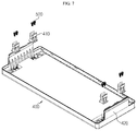
- FIG. 1 is a schematic perspective view of a top cover separated from a battery pack, according to an embodiment of the present disclosure.
- FIG. 2 is a schematic side view of a top cover separated from a battery pack, according to an embodiment of the present disclosure.
- FIG. 3 is a cross-sectional view of a top cover separated from a battery pack, according to an embodiment of the present disclosure.
- FIG. 4 is a cross-sectional view of a top cover combined to a battery pack, according to an embodiment of the present disclosure.
- FIG. 5 is an enlarged view of a region A of FIG. 3 .
- FIG. 6 is an enlarged view of a region B of FIG. 4 .
- FIG. 7 illustrates a bottom surface of a top cover from which a hook protrusion is separated in a battery pack, according to an embodiment of the present disclosure.
- FIG. 1 is a schematic perspective view of a top cover separated from a battery pack, according to an embodiment of the present disclosure
- FIG. 2 is a schematic side view of a top cover separated from a battery pack, according to an embodiment of the present disclosure
- FIG. 3 is a cross-sectional view of a top cover separated from a battery pack, according to an embodiment of the present disclosure
- FIG. 4 is a cross-sectional view of a top cover combined to a battery pack, according to an embodiment of the present disclosure.
- a battery pack 10 in a battery pack 10 according to an embodiment of the present disclosure, a plurality of battery modules 100 are stacked on each other, a case 200 accommodates and protects the stacked plurality of battery modules 100 , and a handle rod 300 is combined to the case 200 for easiness of transportation or movement.
- the battery pack 10 may include various devices for controlling charging or discharging of the battery module 100 , such as a battery management system (BMS), a current sensor, a fuse, etc.
- BMS battery management system
- the battery module 100 may include a plurality of battery cells.
- the battery cell may have a structure in which a plurality of unit cells arranged in an order of positive electrode plate-separator-negative electrode plate or bi-cells arranged in an order of positive electrode plate-separator-negative electrode plate-separator-positive electrode plate-separator-negative electrode plate are stacked on each other according to battery capacity.
- the battery cell may include an electrode lead.
- the electrode lead is a type of terminal externally exposed to be connected to an external device, and may be formed of a conductive material.
- the electrode leads may include a positive electrode lead and a negative electrode lead.
- the positive electrode lead and the negative electrode lead may be provided in opposite directions with respect to a length direction of the battery cell, or the positive electrode lead and the negative electrode lead may be located in the same direction with respect to the length direction of the battery cell.
- the battery module 100 may include a plurality of cartridges accommodating the battery cells. Each cartridge may be manufactured via injection molding of plastic, and the plurality of cartridges having an accommodating portion in which the battery cell is accommodated may be stacked on each other.
- a cartridge assembly in which the plurality of cartridges are stacked on each other may include a connector element or a terminal element.
- the connector element may include, for example, an electric connection part or a connection part of any shape to be connected to a BMS (not shown) for providing data regarding a voltage or temperature of the battery cell.
- the terminal element includes a positive electrode terminal and a negative electrode terminal as a main terminal connected to the battery cell, and the terminal element may be electrically connected to the outside by including a terminal bolt.
- the case 200 may accommodate one or more battery modules 100 .
- at least one battery module 100 is stacked inside the case 200 , and the case 200 surrounds and protects the battery module 100 .
- the case 200 surrounds the entire battery module 100 and accordingly protects the battery module 100 from external vibration or impact.
- the case 200 may have a shape corresponding to a shape of the battery module 100 .
- the case 200 may also have a corresponding hexahedron shape.
- the case 200 may be manufactured by, for example, bending a plate of a metal material, and accordingly, the case 200 may be integrally manufactured.
- a combining process may be easy and simple.
- the case 200 may be manufactured as a separated type, and the cases 200 may be combined by using one of various methods, such as a welding method, a rivet method, a bolt method, a pin method, a bracket method, a moment connection method, etc.
- a grip groove 210 for gripping the handle rod 300 described below may be formed on the case 200 .
- the handle rod 300 formed as a round rod may be embedded inside the case 200 , and at this time, the grip groove 210 on which a hand or an operator is put such that the operator easily hold the handle rod 300 may be formed on the case 200 .
- the handle rod 300 is embedded in the case 200 , and may be used as a handle while the battery pack 10 is moved. Also, referring to FIG. 1 , the handle rod 300 may be provided in a pair to be each combined to the case 200 . In other words, the pair of handle rods 300 may respectively be combined to two end portions of the case 200 .
- the handle rod 300 has a round rod shape of a cylindrical shape, in which a cross-section is circular, and the handle rod 300 having the round rod shape does not protrude outside the case 200 by being combined to the case 200 to be embedded inside the case 200 .
- an externally protruding handle bumped into and interfered with a wall, another battery pack 10 , or the like, and thus an extra space for the externally protruding handle needed to be obtained, and accordingly, space utility efficiency was low.
- the handle rod 300 is embedded inside the case 200 and thus does not interfere with another object, and accordingly, space utility efficiency is increased.
- FIG. 5 is an enlarged view of a region A of FIG. 3
- FIG. 6 is an enlarged view of a region B of FIG. 4
- FIG. 7 is a view of a bottom surface of a top cover from which a hook protrusion is separated in a battery pack, according to an embodiment of the present disclosure.
- a top cover 400 is combined to the handle rod 300 to seal the case 200 , and protects the battery modules 100 inside the case 200 .
- a hook protrusion 410 is formed on the top cover 400 to be combined to the handle rod 300 .
- the top cover 400 may be combined to the case 200 by a locking member, such as a bolt and a nut.
- a locking member such as a bolt and a nut.
- the hook protrusion 410 is formed on the top cover 400 and is combined to the handle rod 300 , and thus the top cover 400 may be easily combined to the handle rod 300 without having to use a separate locking member, such as a bolt and a nut, and in addition, the top cover 400 may be easily separated from the handle rod 300 .
- the battery pack 10 may be moved by using the handle rod 300 embedded inside the case 200 .
- a method of coupling the top cover 400 and the case 200 by using a bolt and a nut is not completely excluded in the battery pack 10 according to the current embodiment, and for example, the top cover 400 and the case 200 may be combined by using a bolt and a nut when there is low possibility that the battery pack 10 may be transported and moved by being fixed for a long period of time after being moved to a predetermined location.
- the hook protrusion 410 may include a rod accommodating portion 411 and an extending portion 412 .
- the handle rod 300 may be inserted into and accommodated in the rod accommodating portion 411 .
- the rod accommodating portion 411 may have a shape corresponding to a cross-section of the handle rod 300 so as to accommodate the handle rod 300 .
- the rod accommodating portion 411 may be substantially prepared to include a circular shape.
- the extending portion 412 extends from the rod accommodating portion 411 such that the handle rod 300 is easily inserted into the rod accommodating portion 411 .
- the rod accommodating portion 411 and the extending portion 412 of the hook protrusion 410 are pressurized, and at this time, when the rod accommodating portion 411 and the extending portion 412 are formed of an elastic material, the rod accommodating portion 411 and the extending portion 412 are elastically deformed and opened such that the handle rod 300 is inserted into and accommodated in the rod accommodating portion 411 . Accordingly, the top cover 400 may be easily combined to or separated from the handle rod 300 .
- the hook protrusion 410 may be prepared in a separated type, and combined to the top cover 400 by using a coupling bolt 500 .
- a method of combining the hook protrusion 410 to the top cover 400 is not limited thereto, and the hook protrusion 410 and the top cover 400 may be integrally manufactured via injection molding.
- four hook protrusions 410 are illustrated, but the number of hook protrusions 410 is not limited thereto.
- a cover portion 420 extends from the top cover 400 , and is prepared to close the grip groove 210 described above.
- the cover portion 420 prevents foreign substances, such as fine dust, from entering the inside through the grip groove 210 , and also prevents the handle rod 300 and the hook protrusion 410 from being damaged from an external impact.
- the cover portion 420 may be variously formed, and specifically, may be integrally manufactured with the top cover 400 via injection molding.
- the battery pack 10 includes the case 200 accommodating the battery module 100 so as to protect the battery module 100 , and the handle rod 300 is combined to the case 200 for convenience and easiness of transportation or movement of the battery pack 10 .
- the handle rod 300 is embedded in the case 200 so as to prevent the handle rod 300 from interfering with another object, such as a wall, another battery pack 10 , or the like.
- the top cover 400 having the hook protrusion 410 is provided to protect the battery module 100 accommodated in the case 200 , and the top cover 400 may be combined to or separated from the handle rod 300 via the hook protrusion 410 .
- the top cover 400 is separated from the handle rod 300 by using the hook protrusion 410 , and then the operator transports or moves the battery pack 10 by holding the handle rod 300 .
- the top cover 400 is combined to the handle rod 300 by using the hook protrusion 410 .
- a vehicle (not shown) may include the battery pack 10 described above, and the battery pack 10 may include the battery module 100 .
- the battery pack 10 according to an embodiment of the present disclosure may be applied to the vehicle (not shown), for example, a predetermined vehicle (not shown) prepared to use electricity, such as an electric car or a hybrid car.
- the present disclosure relates to a battery pack, and in particular, is usable in industries related to secondary batteries.
Landscapes
- Chemical & Material Sciences (AREA)
- Chemical Kinetics & Catalysis (AREA)
- Electrochemistry (AREA)
- General Chemical & Material Sciences (AREA)
- Battery Mounting, Suspending (AREA)
Abstract
Description
Claims (10)
Applications Claiming Priority (3)
| Application Number | Priority Date | Filing Date | Title |
|---|---|---|---|
| KR10-2016-0002620 | 2016-01-08 | ||
| KR1020160002620A KR102021110B1 (en) | 2016-01-08 | 2016-01-08 | Battery pack |
| PCT/KR2017/000214 WO2017119775A1 (en) | 2016-01-08 | 2017-01-06 | Battery pack |
Publications (2)
| Publication Number | Publication Date |
|---|---|
| US20180175341A1 US20180175341A1 (en) | 2018-06-21 |
| US10673036B2 true US10673036B2 (en) | 2020-06-02 |
Family
ID=59273825
Family Applications (1)
| Application Number | Title | Priority Date | Filing Date |
|---|---|---|---|
| US15/578,945 Active US10673036B2 (en) | 2016-01-08 | 2017-01-06 | Battery pack |
Country Status (6)
| Country | Link |
|---|---|
| US (1) | US10673036B2 (en) |
| EP (1) | EP3297061B1 (en) |
| JP (1) | JP6633193B2 (en) |
| KR (1) | KR102021110B1 (en) |
| CN (1) | CN107710451B (en) |
| WO (1) | WO2017119775A1 (en) |
Cited By (1)
| Publication number | Priority date | Publication date | Assignee | Title |
|---|---|---|---|---|
| USD987557S1 (en) * | 2021-01-04 | 2023-05-30 | Lg Energy Solution, Ltd. | Battery pack |
Families Citing this family (11)
| Publication number | Priority date | Publication date | Assignee | Title |
|---|---|---|---|---|
| KR102010018B1 (en) * | 2016-02-24 | 2019-08-12 | 주식회사 엘지화학 | Electric box for battery pack and battery pack structure using thereof |
| KR102133554B1 (en) * | 2016-10-21 | 2020-07-13 | 주식회사 엘지화학 | Battery pack |
| KR102248230B1 (en) * | 2017-12-07 | 2021-05-03 | 주식회사 엘지화학 | Secondary battery module |
| KR102081194B1 (en) * | 2018-07-11 | 2020-02-25 | 세방전지(주) | System mounting handle on battery case and, method for operating the same |
| DE102018217022A1 (en) * | 2018-10-04 | 2020-04-09 | Robert Bosch Gmbh | Battery module |
| AU2020362049A1 (en) | 2019-10-11 | 2022-05-19 | Ariens Company | Power source and control system for a lawn mower |
| KR102812829B1 (en) * | 2020-03-05 | 2025-05-23 | 주식회사 엘지에너지솔루션 | Battery pack with structure of improved convenience for carrying and assembling and improved safety |
| KR102684808B1 (en) * | 2020-03-25 | 2024-07-11 | 주식회사 엘지에너지솔루션 | Battery Pack with a handle which has a loose stopper |
| US20240170791A1 (en) * | 2021-12-27 | 2024-05-23 | Lg Energy Solution, Ltd. | Battery pack |
| USD1106942S1 (en) * | 2023-01-31 | 2025-12-23 | Hanwha Solutions Corporation | Battery pack |
| USD1110941S1 (en) * | 2023-08-08 | 2026-02-03 | Hanwha Solutions Corporation | Battery pack |
Citations (21)
| Publication number | Priority date | Publication date | Assignee | Title |
|---|---|---|---|---|
| US4013819A (en) * | 1975-08-27 | 1977-03-22 | Varta Batteries Limited | Handle construction for batteries |
| JPS5428030U (en) | 1977-07-29 | 1979-02-23 | ||
| JPS5632373U (en) | 1979-08-22 | 1981-03-30 | ||
| GB2081495A (en) | 1980-07-07 | 1982-02-17 | Fiat Ricerche | Electrical energy storage and supply unit for electric vehicles |
| JPS61196461U (en) | 1985-05-30 | 1986-12-08 | ||
| JPS6332455U (en) | 1986-08-13 | 1988-03-02 | ||
| KR940025572U (en) | 1993-04-19 | 1994-11-18 | Battery Carrying Handle | |
| US20040175609A1 (en) * | 2003-03-03 | 2004-09-09 | Nec Lamilion Energy, Ltd. | Film covered battery and stacked battery assembly |
| US20080182163A1 (en) * | 2007-01-26 | 2008-07-31 | Shenzhen Mindray Bio-Medical Electronics Co., Ltd. | Battery loading and unloading structure |
| US20110003196A1 (en) * | 2009-07-06 | 2011-01-06 | Samsung Sdi Co., Ltd. | Battery pack |
| KR101174045B1 (en) | 2010-09-29 | 2012-08-16 | 주식회사 명신이엔지 | Battery pack and battery pack assembly having the same |
| JP2013105723A (en) | 2011-11-16 | 2013-05-30 | Panasonic Corp | Power storage device |
| KR101285712B1 (en) | 2012-02-27 | 2013-07-12 | 세방전지(주) | Battery pack case |
| WO2014155903A1 (en) | 2013-03-29 | 2014-10-02 | パナソニック株式会社 | Battery pack |
| CN204067462U (en) | 2014-08-13 | 2014-12-31 | 宁波世捷新能源科技有限公司 | Portable high performance lithium ion battery module cage in groups |
| EP2833436A1 (en) | 2013-07-31 | 2015-02-04 | LG Chem, Ltd. | Battery pack having structure for mounting to the outside |
| WO2015016564A1 (en) | 2013-07-31 | 2015-02-05 | 주식회사 엘지화학 | Battery module assembly having refrigerant fluid channel |
| KR101512088B1 (en) | 2013-04-29 | 2015-04-14 | 주식회사 엘지화학 | Inner case of battery module assembly for vehicle's battery pack |
| CN204792929U (en) | 2015-06-30 | 2015-11-18 | 山东精工电子科技有限公司 | But cleaning cart is with connection in series -parallel lithium cell group |
| KR20150136842A (en) | 2014-05-28 | 2015-12-08 | 주식회사 엘지화학 | Terminal cover and battery module including the same |
| US20160197323A1 (en) * | 2015-01-05 | 2016-07-07 | Johnson Controls Technology Company | Battery module vent and handle configuration system and method |
Family Cites Families (5)
| Publication number | Priority date | Publication date | Assignee | Title |
|---|---|---|---|---|
| JPS57152765U (en) * | 1981-03-20 | 1982-09-25 | ||
| JPS5920557U (en) * | 1982-07-29 | 1984-02-08 | 新神戸電機株式会社 | Storage battery handle |
| KR101499930B1 (en) | 2013-07-29 | 2015-03-09 | 주식회사 이랜텍 | Batterypack case |
| WO2015045401A1 (en) * | 2013-09-30 | 2015-04-02 | パナソニックIpマネジメント株式会社 | Battery-affixing frame member, battery-affixing member, and electricity storage device |
| KR20160002620A (en) | 2015-12-15 | 2016-01-08 | 박지배 | Soil retaining wall and construction method thereof |
-
2016
- 2016-01-08 KR KR1020160002620A patent/KR102021110B1/en active Active
-
2017
- 2017-01-06 CN CN201780002080.6A patent/CN107710451B/en active Active
- 2017-01-06 JP JP2018517248A patent/JP6633193B2/en active Active
- 2017-01-06 EP EP17736147.4A patent/EP3297061B1/en active Active
- 2017-01-06 WO PCT/KR2017/000214 patent/WO2017119775A1/en not_active Ceased
- 2017-01-06 US US15/578,945 patent/US10673036B2/en active Active
Patent Citations (25)
| Publication number | Priority date | Publication date | Assignee | Title |
|---|---|---|---|---|
| US4013819A (en) * | 1975-08-27 | 1977-03-22 | Varta Batteries Limited | Handle construction for batteries |
| JPS5428030U (en) | 1977-07-29 | 1979-02-23 | ||
| JPS5632373U (en) | 1979-08-22 | 1981-03-30 | ||
| GB2081495A (en) | 1980-07-07 | 1982-02-17 | Fiat Ricerche | Electrical energy storage and supply unit for electric vehicles |
| JPS61196461U (en) | 1985-05-30 | 1986-12-08 | ||
| JPS6332455U (en) | 1986-08-13 | 1988-03-02 | ||
| KR940025572U (en) | 1993-04-19 | 1994-11-18 | Battery Carrying Handle | |
| US20040175609A1 (en) * | 2003-03-03 | 2004-09-09 | Nec Lamilion Energy, Ltd. | Film covered battery and stacked battery assembly |
| US20080182163A1 (en) * | 2007-01-26 | 2008-07-31 | Shenzhen Mindray Bio-Medical Electronics Co., Ltd. | Battery loading and unloading structure |
| US20110003196A1 (en) * | 2009-07-06 | 2011-01-06 | Samsung Sdi Co., Ltd. | Battery pack |
| KR101174045B1 (en) | 2010-09-29 | 2012-08-16 | 주식회사 명신이엔지 | Battery pack and battery pack assembly having the same |
| JP2013105723A (en) | 2011-11-16 | 2013-05-30 | Panasonic Corp | Power storage device |
| KR101285712B1 (en) | 2012-02-27 | 2013-07-12 | 세방전지(주) | Battery pack case |
| US20130224541A1 (en) * | 2012-02-27 | 2013-08-29 | Global Battery Co., Ltd. | Battery pack case |
| WO2014155903A1 (en) | 2013-03-29 | 2014-10-02 | パナソニック株式会社 | Battery pack |
| US20160006085A1 (en) * | 2013-03-29 | 2016-01-07 | Panasonic Intellectual Property Management Co., Ltd. | Battery pack |
| KR101512088B1 (en) | 2013-04-29 | 2015-04-14 | 주식회사 엘지화학 | Inner case of battery module assembly for vehicle's battery pack |
| US20150111083A1 (en) | 2013-04-29 | 2015-04-23 | Lg Chem, Ltd. | Inner case of battery module assembly for vehicle's battery pack |
| EP2833436A1 (en) | 2013-07-31 | 2015-02-04 | LG Chem, Ltd. | Battery pack having structure for mounting to the outside |
| WO2015016564A1 (en) | 2013-07-31 | 2015-02-05 | 주식회사 엘지화학 | Battery module assembly having refrigerant fluid channel |
| US20160134000A1 (en) | 2013-07-31 | 2016-05-12 | Lg Chem, Ltd. | Battery module assembly having coolant flow channel |
| KR20150136842A (en) | 2014-05-28 | 2015-12-08 | 주식회사 엘지화학 | Terminal cover and battery module including the same |
| CN204067462U (en) | 2014-08-13 | 2014-12-31 | 宁波世捷新能源科技有限公司 | Portable high performance lithium ion battery module cage in groups |
| US20160197323A1 (en) * | 2015-01-05 | 2016-07-07 | Johnson Controls Technology Company | Battery module vent and handle configuration system and method |
| CN204792929U (en) | 2015-06-30 | 2015-11-18 | 山东精工电子科技有限公司 | But cleaning cart is with connection in series -parallel lithium cell group |
Non-Patent Citations (1)
| Title |
|---|
| International Search Report, issued in PCT/KR2017/000214, dated Apr. 27, 2017. |
Cited By (1)
| Publication number | Priority date | Publication date | Assignee | Title |
|---|---|---|---|---|
| USD987557S1 (en) * | 2021-01-04 | 2023-05-30 | Lg Energy Solution, Ltd. | Battery pack |
Also Published As
| Publication number | Publication date |
|---|---|
| EP3297061A1 (en) | 2018-03-21 |
| US20180175341A1 (en) | 2018-06-21 |
| JP2018530880A (en) | 2018-10-18 |
| KR20170083311A (en) | 2017-07-18 |
| EP3297061A4 (en) | 2018-04-04 |
| WO2017119775A1 (en) | 2017-07-13 |
| CN107710451B (en) | 2020-09-18 |
| EP3297061B1 (en) | 2020-03-04 |
| JP6633193B2 (en) | 2020-01-22 |
| CN107710451A (en) | 2018-02-16 |
| KR102021110B1 (en) | 2019-09-11 |
Similar Documents
| Publication | Publication Date | Title |
|---|---|---|
| US10673036B2 (en) | Battery pack | |
| US10243193B2 (en) | Battery pack | |
| US11121395B2 (en) | Battery module with movable end plate responsive to cell swelling and battery pack including same | |
| US10461288B2 (en) | Battery module and battery pack including same | |
| EP4152503B1 (en) | Battery pack and vehicle comprising same | |
| US11342621B2 (en) | Battery pack | |
| US11152671B2 (en) | Battery module and battery pack including the same | |
| US20190189982A1 (en) | Battery module and battery pack including same | |
| KR102067714B1 (en) | Battery module and battery pack including the same | |
| US20150064502A1 (en) | Battery pack | |
| US20150050538A1 (en) | Energy storage apparatus | |
| KR20190007745A (en) | Battery pack | |
| KR20170054881A (en) | Battery module and battery pack including the same | |
| EP3285313B1 (en) | Battery module and battery pack comprising same | |
| KR102244138B1 (en) | Battery module and battery pack including the same | |
| KR20210049327A (en) | Busbar Having Anticorrosion Member and Battery Module Including The Same | |
| EP4625655A1 (en) | Battery pack including battery module and vehicle including same | |
| EP4336639B1 (en) | Battery module and battery pack and vehicle comprising same | |
| KR102714029B1 (en) | Battery module and battery pack including the same and vehicle including the same |
Legal Events
| Date | Code | Title | Description |
|---|---|---|---|
| FEPP | Fee payment procedure |
Free format text: ENTITY STATUS SET TO UNDISCOUNTED (ORIGINAL EVENT CODE: BIG.); ENTITY STATUS OF PATENT OWNER: LARGE ENTITY |
|
| AS | Assignment |
Owner name: LG CHEM, LTD., KOREA, REPUBLIC OF Free format text: ASSIGNMENT OF ASSIGNORS INTEREST;ASSIGNORS:KIM, HYEON-KYU;SEOL, JAE-JUNG;LEE, BUM-HYUN;AND OTHERS;REEL/FRAME:044680/0042 Effective date: 20170904 |
|
| STPP | Information on status: patent application and granting procedure in general |
Free format text: NON FINAL ACTION MAILED |
|
| STPP | Information on status: patent application and granting procedure in general |
Free format text: RESPONSE TO NON-FINAL OFFICE ACTION ENTERED AND FORWARDED TO EXAMINER |
|
| STPP | Information on status: patent application and granting procedure in general |
Free format text: FINAL REJECTION MAILED |
|
| STPP | Information on status: patent application and granting procedure in general |
Free format text: ADVISORY ACTION MAILED |
|
| STPP | Information on status: patent application and granting procedure in general |
Free format text: DOCKETED NEW CASE - READY FOR EXAMINATION |
|
| STPP | Information on status: patent application and granting procedure in general |
Free format text: NON FINAL ACTION MAILED |
|
| STPP | Information on status: patent application and granting procedure in general |
Free format text: PUBLICATIONS -- ISSUE FEE PAYMENT RECEIVED |
|
| STCF | Information on status: patent grant |
Free format text: PATENTED CASE |
|
| AS | Assignment |
Owner name: LG ENERGY SOLUTION, LTD., KOREA, REPUBLIC OF Free format text: ASSIGNMENT OF ASSIGNORS INTEREST;ASSIGNOR:LG CHEM, LTD.;REEL/FRAME:058295/0068 Effective date: 20211027 Owner name: LG ENERGY SOLUTION, LTD., KOREA, REPUBLIC OF Free format text: ASSIGNMENT OF ASSIGNOR'S INTEREST;ASSIGNOR:LG CHEM, LTD.;REEL/FRAME:058295/0068 Effective date: 20211027 |
|
| MAFP | Maintenance fee payment |
Free format text: PAYMENT OF MAINTENANCE FEE, 4TH YEAR, LARGE ENTITY (ORIGINAL EVENT CODE: M1551); ENTITY STATUS OF PATENT OWNER: LARGE ENTITY Year of fee payment: 4 |